

EN 1990-1:2023+A1:2026/prA2
(Amendment)Eurocode - Basis of structural and geotechnical design - Part 1: New structures
- Abstract
1.1 Scope of !EN 1990-1
(1) This document establishes principles and requirements for the safety, serviceability, robustness and durability of structures, including geotechnical structures, appropriate to the consequences of failure.
(2) This document is also applicable for existing structures as specified in EN 1990-2.
(3) This document is intended to be used in conjunction with the other Eurocodes for the design of buildings and civil engineering works, including temporary structures.
(4) This document describes the basis for structural and geotechnical verification according to the limit state principle.
(5) The verification methods in this document are based primarily on the partial factor method.
NOTE 1 Alternative methods are given in the other Eurocodes for specific applications.
NOTE 2 The Annexes to this document also provide general guidance concerning the use of alternative methods.
deleted text
(6) This document is also applicable for the design of structures where materials or actions outside the scope of EN 1991 (all parts) to EN 1999 (all parts) are involved.
NOTE In this case, additional or amended provisions can be necessary.
1.2 Assumptions
(1) It is assumed that reasonable skill and care appropriate to the circumstances is exercised in the design, based on the knowledge and good practice generally available at the time the structure is designed.
(2) It is assumed that the design of the structure is made by appropriately qualified and experienced personnel.
(3) The design rules provided in the Eurocodes assume that:
- execution will be carried out by personnel having appropriate skill and experience;
- adequate control and supervision will be provided during design and execution of the works, whether in factories, plants, or on site;
- construction materials and products for new structures or new structural members will be used in accordance with the Eurocodes, the relevant product and execution standards, and project specifications;
- the structure will be adequately inspected and maintained;
- the structure will be used in accordance with the assumptions.
NOTE Guidance on management measures to satisfy the assumptions for design, verification and execution is given in Annex B.
- Status
- Not Published
- Publication Date
- 23-Nov-2027
- Technical Committee
- CEN/TC 250 - Structural Eurocodes
- Drafting Committee
- CEN/TC 250/SC 10 - EN 1990 Basis of structural design
- Current Stage
- 4020 - Submission to enquiry - Enquiry
- Start Date
- 10-Sep-2026
- Due Date
- 30-Oct-2026
- Completion Date
- 10-Sep-2026

EN 1990-1:2023+A1:2026/prA2 is a CEN draft amendment to Eurocode - Basis of structural and geotechnical design - Part 1: New structures. It sets the basis for checking safety, serviceability, robustness and durability of structures and geotechnical structures, mainly by the partial factor method, for use with the other Eurocodes. The amendment also adds guidance for design assisted by testing and by numerical methods.
What does EN 1990-1:2023+A1:2026/prA2 specify?
EN 1990-1:2023+A1:2026/prA2 specifies the Eurocode basis for structural and geotechnical verification for new structures, including temporary structures. It also applies to existing structures as referenced by EN 1990-2, and it can be used when materials or actions outside EN 1991 to EN 1999 and EN 19100 are involved, with extra or amended provisions where needed.
The document is organized as a change set. It modifies the whole document and specific Clauses 0, 2, 3, 4, 6, 7 and 8, then updates Annexes A, D, E and G and adds a new informative Annex J.
| Annex | What it covers |
|---|---|
| Annex A | Application rules, including combinations and partial factors |
| Annex D | Design assisted by testing |
| Annex E | Additional guidance for enhancing the robustness of buildings and bridges |
| Annex G | Basis of design for bearings |
| Annex J | Design assisted by numerical methods |
What are the key requirements of EN 1990-1:2023+A1:2026/prA2?
EN 1990-1:2023+A1:2026/prA2 keeps the core Eurocode rule set: designers verify limit states, use the partial factor method as the main verification format, and rely on the other Eurocodes for alternative methods and detailed application rules. In practice, this means the document is the starting point for the design basis, not a standalone design code for every material or action.
Design basis and assumptions
Clause 1 requires designs to be based on reasonable skill and care, qualified personnel, adequate supervision, suitable materials and products, inspection, maintenance and use in line with the assumptions. Annex B is identified as the place where guidance on management measures supports those assumptions. For a project team, this means the technical design must be matched by proper execution and control.
Clause 4 ties EN 1990-1 to EN 1999 and EN 19100, and the scope note states that the document is intended to be used with the other Eurocodes for buildings, civil engineering works and temporary structures. In practice, the standard is part of a coordinated design package, not a single isolated document.
Verification and basic variables
Clause 6 adds a rule for system-level verification: the characteristic value of a material or product property may be taken as a mean value, provided the partial factors are chosen accordingly. That matters when a global system check is more appropriate than a member-by-member check, because the statistic used for the material property changes the way the safety format is applied.
Clause 8 keeps the partial factor method as the main verification route and updates how resistance values, action effects and model uncertainty are handled. It also adds guidance for the direct method when resistance is determined by numerical incremental analysis, including a load amplification factor and combined factor treatment for system-level verifications.
Structural and geotechnical analysis, testing and numerical methods
Clause 7 extends the analysis provisions to both structural and geotechnical models and states that models should be validated and verified. Annex J then gives the detailed guidance for numerical methods, including finite element (FE) methods and other numerical modelling techniques. For a designer, this means numerical analysis is accepted, but only if the model is checked for physical realism, numerical accuracy and suitability for the intended domain.
Annex J separates two routes:
- the indirect method, where the numerical model provides effects of actions and a separate resistance model is used
- the direct method, where resistance comes directly from the numerical model
That distinction matters because it changes what must be validated, what uncertainties must be included and how partial factors are applied.
Annex-specific application rules and guidance
Annex A updates application rules for combinations, including wind with traffic, permanent actions from a single source, uplift and variable construction actions. In practice, these changes affect how load combinations and partial factors are selected for equilibrium checks, bridge situations and construction-stage verification.
Annex D updates design assisted by testing, including how uncertainty is treated when the variation is known or unknown, and it revises the tabulated factors used in the method. Annex E and Annex G receive targeted updates for robustness and bearing design, respectively, so project teams using those topics should follow the updated text rather than older cross-references.
What terms does EN 1990-1:2023+A1:2026/prA2 define?
- Verification - confirmation that a limit state will not be exceeded.
- Validation - checking that a numerical model and its input parameters adequately represent the relevant physical behaviour for the intended purpose.
- Indirect method - a numerical design route where verification uses action effects from a model and a separate resistance model from the relevant Eurocode.
- Direct method - a numerical design route where verification uses the resistance obtained directly from the numerical model.
- Numerical model - a calculation model based on numerical approximation, including FE, finite-difference, boundary element, discrete-element and subgrade reaction methods.
- Load amplification factor - the factor used in direct methods to scale actions in incremental numerical analysis.
- Reference solution - an analytical or numerical benchmark used to validate or verify numerical results.
- Sub-modelling - modelling a local part of a larger model to capture refined behaviour in a smaller domain.
Who uses EN 1990-1:2023+A1:2026/prA2?
EN 1990-1:2023+A1:2026/prA2 is used by structural engineers, geotechnical engineers and calculation checkers who need the common Eurocode basis for safety verification. It also matters to design offices, reviewers, client engineers and authorities that check whether the design basis, load combinations, testing evidence or numerical analysis follow the Eurocode format.
It is relevant in buildings, civil engineering works, temporary structures, bridges, foundations and other structures where structural and geotechnical actions interact. It also supports teams working with testing, monitoring, numerical simulation and robustness checks.
What changed in EN 1990-1:2023+A1:2026/prA2 from the previous edition?
EN 1990-1:2023+A1:2026/prA2 amends EN 1990-1:2023+A1:2026. The foreword states that some changes are editorial corrections, and the technical updates include:
- updated internal references to EN 1991-3:2026 and EN 1991-4:2026
- addition of EN 19100 (all parts) as a normative reference
- new terminology and symbols for numerical methods, including validation, verification, FE and CFD
- expanded Clause 7 and Clause 8 provisions for numerical analysis and direct methods
- updates to Annex A, Annex D, Annex E and Annex G
- addition of informative Annex J on design assisted by numerical methods
Which standards are used with EN 1990-1:2023+A1:2026/prA2?
| Standard | What it contributes |
|---|---|
| EN 19100 (all parts) | Design of glass structures, added as a normative reference |
| EN 1991 (all parts) | Actions on structures and related design input |
| EN 1997 (all parts) | Geotechnical design provisions and resistance models |
| EN 1998 (all parts) | Seismic design provisions used with numerical methods and geotechnical analysis |
| EN 1992 (all parts) to EN 1999 (all parts) | Material-specific Eurocode provisions used with Annex J and other clauses |
What does the EN 1990-1:2023+A1:2026/prA2 document contain?
This draft amendment is mainly a structured list of modifications to the base Eurocode text. It revises definitions, symbols, formulas, notes and tables, especially where numerical methods, partial factors, load combinations and model uncertainty are involved.
It also adds a full informative Annex J with guidance on method selection, validation, verification, modelling assumptions, action models, material models, boundary conditions, contact models and coupled models. Annex J includes a figure showing the direct and indirect methods and formulas for deriving design resistance in direct numerical methods.
The other updated annexes contain practical design material: Annex A for application rules, Annex D for testing-based design, Annex E for robustness guidance and Annex G for bearings.
Get Certified
Connect with accredited certification bodies for this standard

DIBt (Deutsches Institut für Bautechnik)
German Institute for Building Technology.
DIN CERTCO
DIN Group product certification.

Aboma Certification B.V.
Specialized in construction, metal, and transport sectors.
Sponsored listings
Frequently Asked Questions
EN 1990-1:2023+A1:2026/prA2 is a draft published by the European Committee for Standardization (CEN). Its full title is "Eurocode - Basis of structural and geotechnical design - Part 1: New structures". This standard covers: 1.1 Scope of !EN 1990-1 (1) This document establishes principles and requirements for the safety, serviceability, robustness and durability of structures, including geotechnical structures, appropriate to the consequences of failure. (2) This document is also applicable for existing structures as specified in EN 1990-2. (3) This document is intended to be used in conjunction with the other Eurocodes for the design of buildings and civil engineering works, including temporary structures. (4) This document describes the basis for structural and geotechnical verification according to the limit state principle. (5) The verification methods in this document are based primarily on the partial factor method. NOTE 1 Alternative methods are given in the other Eurocodes for specific applications. NOTE 2 The Annexes to this document also provide general guidance concerning the use of alternative methods. deleted text (6) This document is also applicable for the design of structures where materials or actions outside the scope of EN 1991 (all parts) to EN 1999 (all parts) are involved. NOTE In this case, additional or amended provisions can be necessary. 1.2 Assumptions (1) It is assumed that reasonable skill and care appropriate to the circumstances is exercised in the design, based on the knowledge and good practice generally available at the time the structure is designed. (2) It is assumed that the design of the structure is made by appropriately qualified and experienced personnel. (3) The design rules provided in the Eurocodes assume that: - execution will be carried out by personnel having appropriate skill and experience; - adequate control and supervision will be provided during design and execution of the works, whether in factories, plants, or on site; - construction materials and products for new structures or new structural members will be used in accordance with the Eurocodes, the relevant product and execution standards, and project specifications; - the structure will be adequately inspected and maintained; - the structure will be used in accordance with the assumptions. NOTE Guidance on management measures to satisfy the assumptions for design, verification and execution is given in Annex B.
1.1 Scope of !EN 1990-1 (1) This document establishes principles and requirements for the safety, serviceability, robustness and durability of structures, including geotechnical structures, appropriate to the consequences of failure. (2) This document is also applicable for existing structures as specified in EN 1990-2. (3) This document is intended to be used in conjunction with the other Eurocodes for the design of buildings and civil engineering works, including temporary structures. (4) This document describes the basis for structural and geotechnical verification according to the limit state principle. (5) The verification methods in this document are based primarily on the partial factor method. NOTE 1 Alternative methods are given in the other Eurocodes for specific applications. NOTE 2 The Annexes to this document also provide general guidance concerning the use of alternative methods. deleted text (6) This document is also applicable for the design of structures where materials or actions outside the scope of EN 1991 (all parts) to EN 1999 (all parts) are involved. NOTE In this case, additional or amended provisions can be necessary. 1.2 Assumptions (1) It is assumed that reasonable skill and care appropriate to the circumstances is exercised in the design, based on the knowledge and good practice generally available at the time the structure is designed. (2) It is assumed that the design of the structure is made by appropriately qualified and experienced personnel. (3) The design rules provided in the Eurocodes assume that: - execution will be carried out by personnel having appropriate skill and experience; - adequate control and supervision will be provided during design and execution of the works, whether in factories, plants, or on site; - construction materials and products for new structures or new structural members will be used in accordance with the Eurocodes, the relevant product and execution standards, and project specifications; - the structure will be adequately inspected and maintained; - the structure will be used in accordance with the assumptions. NOTE Guidance on management measures to satisfy the assumptions for design, verification and execution is given in Annex B.
EN 1990-1:2023+A1:2026/prA2 is classified under the following ICS (International Classification for Standards) categories: 91.010.30 - Technical aspects. The ICS classification helps identify the subject area and facilitates finding related standards.
EN 1990-1:2023+A1:2026/prA2 is available in PDF format for immediate download after purchase. The document can be added to your cart and obtained through the secure checkout process. Digital delivery ensures instant access to the complete standard document.
Standards Content (Sample)
SLOVENSKI STANDARD
01-november-2026
Evrokod - Osnove projektiranja konstrukcij in geotehničnega projektiranja - 1. del:
Nove konstrukcije
Eurocode - Basis of structural and geotechnical design - Part 1: New structures
Eurocode - Grundlagen der Tragwerksplanung und Planung geotechnischer Bauwerke -
Teil 1: Neubauten
Eurocode - Bases des calculs structuraux et géotechniques - Partie 1 : Structures
neuves
Ta slovenski standard je istoveten z: EN 1990-1:2023+A1:2026/prA2
ICS:
91.010.30 Tehnični vidiki Technical aspects
SIST EN 1990- en,fr,de
1:2023+A1:2026/oprA2:2026
2003-01.Slovenski inštitut za standardizacijo. Razmnoževanje celote ali delov tega standarda ni dovoljeno.
DRAFT
EUROPEAN STANDARD
EN 1990-
NORME EUROPÉENNE
1:2023+A1:2026
EUROPÄISCHE NORM
prA2
September 2026
ICS 91.010.30
English Version
Eurocode - Basis of structural and geotechnical design -
Part 1: New structures
Eurocode - Bases des calculs structuraux et Eurocode - Grundlagen der Tragwerksplanung und
géotechniques - Partie 1 : Structures neuves Planung geotechnischer Bauwerke - Teil 1: Neubauten
This draft amendment is submitted to CEN members for enquiry. It has been drawn up by the Technical Committee CEN/TC 250.
This draft amendment A2, if approved, will modify the European Standard EN 1990-1:2023+A1:2026. If this draft becomes an
amendment, CEN members are bound to comply with the CEN/CENELEC Internal Regulations which stipulate the conditions for
inclusion of this amendment into the relevant national standard without any alteration.
This draft amendment was established by CEN in three official versions (English, French, German). A version in any other
language made by translation under the responsibility of a CEN member into its own language and notified to the CEN-CENELEC
Management Centre has the same status as the official versions.
CEN members are the national standards bodies of Austria, Belgium, Bulgaria, Croatia, Cyprus, Czech Republic, Denmark, Estonia,
Finland, France, Germany, Greece, Hungary, Iceland, Ireland, Italy, Latvia, Lithuania, Luxembourg, Malta, Netherlands, Norway,
Poland, Portugal, Republic of North Macedonia, Romania, Serbia, Slovakia, Slovenia, Spain, Sweden, Switzerland, Türkiye and
United Kingdom.
Recipients of this draft are invited to submit, with their comments, notification of any relevant patent rights of which they are
aware and to provide supporting documentation.
Warning : This document is not a European Standard. It is distributed for review and comments. It is subject to change without
notice and shall not be referred to as a European Standard.
EUROPEAN COMMITTEE FOR STANDARDIZATION
COMITÉ EUROPÉEN DE NORMALISATION
EUROPÄISCHES KOMITEE FÜR NORMUNG
CEN-CENELEC Management Centre: Rue de la Science 23, B-1040 Brussels
© 2026 CEN All rights of exploitation in any form and by any means reserved Ref. No. EN 1990-1:2023+A1:2026/prA2:2026 E
worldwide for CEN national Members.
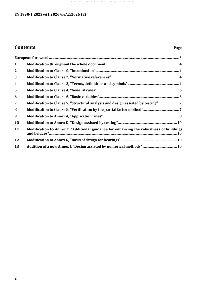
Contents Page
European foreword . 3
1 Modification throughout the whole document . 4
2 Modification to Clause 0, “Introduction” . 4
3 Modification to Clause 2, “Normative references” . 4
4 Modification to Clause 3, “Terms, definitions and symbols” . 4
5 Modification to Clause 4, “General rules” . 6
6 Modification to Clause 6, “Basic variables” . 6
7 Modification to Clause 7, “Structural analysis and design assisted by testing” . 7
8 Modification to Clause 8, “Verification by the partial factor method” . 7
9 Modification to Annex A, “Application rules” . 8
10 Modification to Annex D, “Design assisted by testing” . 10
11 Modification to Annex E, “Additional guidance for enhancing the robustness of buildings
and bridges” . 10
12 Modification to Annex G, “Basis of design for bearings” . 10
13 Addition of a new Annex J, “Design assisted by numerical methods” . 10
European foreword
This document (EN 1990-1:2023+A1:2026/prA2:2026) has been prepared by Technical Committee
CEN/TC 250 “Structural Eurocodes”, the secretariat of which is held by BSI. CEN/TC 250 is responsible
for all Structural Eurocodes and has been assigned responsibility for structural and geotechnical design
matters by CEN.
This document is currently submitted to the CEN Enquiry.
This document will amend EN 1990-1:2023+A1:2026.
NOTE Some modifications are purely editorial corrections to improve the quality of the document and these
will not be tagged in the consolidated publication, as noted after the modification.
The first generation of EN Eurocodes was published between 2002 and 2007. This document forms part
of the second generation of the Eurocodes, which have been prepared under Mandate M/515 issued to
CEN by the European Commission and the European Free Trade Association.
The Eurocodes have been drafted to be used in conjunction with relevant execution, material, product
and test standards, and to identify requirements for execution, materials, products and testing that are
relied upon by the Eurocodes.
The Eurocodes recognize the responsibility of each Member State and have safeguarded their right to
determine values related to regulatory safety matters at national level through the use of National
Annexes.
1 Modification throughout the whole document
Replace “FprEN 1991-3:2025” with “EN 1991-3:2026”.
Replace “FprEN 1991-4:2025” with “EN 1991-4:2026”.
Replace “EN 1991 (all parts) to EN 1999 (all parts)” with “EN 1991 (all parts) to EN 1999 (all parts) and
EN 19100 (all parts)”.
Replace “cranes or machines” with “cranes or other machines”.
Replace “cranes and machines” with “cranes and other machines”.
2 Modification to Clause 0, “Introduction”
0.5 Add the following references in the table with national choices: “J.3.2(1)”, “J.3.3(5)” and “J.6.2.1(4)”.
0.5 Add the following in the table with Informative Annexes: “Annex J”.
3 Modification to Clause 2, “Normative references”
Add the following reference:
EN 19100 (all parts), Eurocode 10 — Design of glass structures
4 Modification to Clause 3, “Terms, definitions and symbols”
3.1.2.9 Replace the word “may” with “can” in the definition of “fatigue design situation”.
3.1.2 Add a new definition 3.1.2.16 verification: “ confirmation that a limit state will not be
exceeded”, then have the subsequent terms renumbered
3.1.2.36 Replace the word “non-renewable” with “natural” in the definition of “sustainability”
3.1.8.1 Replace the source reference “3.2.61” with “3.2.59”.
3.1.8.2 Replace the source reference “3.2.62” with “3.2.60”.
3.1.8.3 Replace the source reference “3.2.52” with “3.2.50”.
3.1.8.4 Replace the source reference “3.2.71” with “3.2.69”.
3.1.8.5 Add “from particulate solids” between the words “traction” and “acting”.
3.1.8.5 Replace the source reference “3.2.65” with “3.2.63”.
3.1.8.6 Replace the source reference “3.2.62” with “3.2.61”.
3.1.8.8 Replace the source reference “3.2.47” with “3.2.45”.
3.1.8.9 Replace the source reference “3.2.74” with “3.2.72”.
3.1.8.10 Replace the source reference “3.2.75” with “3.2.73”.
3.1.9.2 Replace “assembly” with “machine” in the definition and in the source.
3.1.9.2 Delete the NOTE to the entry and “, and NOTE 1 to entry added” in the source.
3.1.9.7 Replace “counterweights, trolley” with “if exist counterweight(s)”.
3.1.9.9 Delete the comma in the definition.
3.1.9.12 Delete the comma in the definition.
3.1 Add the following new subclause 3.1.10:
“3.1.10 Terms relating to numerical methods
3.1.10.1
validation
process of confirming if a model and, where relevant, its input parameters are an
adequate representation of the physical phenomena for the intended purpose
Note 1 to entry: Validation is the domain of physics and can concern empirical methods and/or engineering
theorems.
Note 2 to entry: The validation of a model includes the identification of the application domain.
Note 3 to entry: The validation of a model is needed for the determination of model uncertainty.
3.1.10.2
verification
process of determining that a numerical model sufficiently accurately approximates
a correct solution for the specific project
Note 1 to entry: Verification is the domain of mathematics and concerns the accuracy of numerical methods.
Note 2 to entry: Verification includes also the checks of inputs and outputs for a particular application.
3.1.10.3
indirect method
method in which verification of a limit state is based on the effects of actions (e.g. internal forces, stresses
or generalised deformations) obtained e.g. from a numerical model and the resistance obtained by the
relevant resistance model specified in the appropriate Eurocode, for which partial factors have been
calibrated in compliance with the resistance calculation models and are provided in the same Eurocode
Note 1 to entry: Numerical analyses of geotechnical structures can be considered as belonging to the indirect
design method as long as the resistance models for ground comply with EN 1997 (all parts), all parts and the
resistance models for structural elements comply with the corresponding material Eurocodes.
Note 2 to entry: In some cases, the numerical model acts in conjunction with an advanced material model, not
covered by the other Eurocodes. The material model interacts with the action model. It can depend on the
circumstances whether a combined or separate validation is most adequate.
3.1.10.4
direct method
method in which verification of a limit state is based on the effects of actions (e.g. internal forces, stresses
or generalised deformations) and the (overall or system) resistance obtained directly from the numerical
model
3.1.10.5
reference solution
solution obtained from an analytical or numerical model, and its associated model uncertainty, based on
accepted theory or evidence used to validate and/or to verify the results obtained by the numerical model
used in the design
3.1.10.6
load amplification factor
factor used in direct methods to multiply actions’ values in a numerical analysis to obtain the values of
the effects of actions (demand) and the resistance (capacity)
3.1.10.7
numerical model
calculation model involving numerical approximation
Note 1 to entry: The definition assumes the existence of conceptual structural, geotechnical or action models.
Note 2 to entry: The term Numerical model includes, but is not limited to, finite-element, finite-difference,
boundary element, discrete-element models and subgrade reaction methods.
3.1.10.8
sub-modelling
modelling of a portion of a larger (global) model to capture the effects of refined discretization in a
smaller model
Note 1 to entry: Sub-modelling can be realized either by separation of components or by local extensions of the
level of structural and geotechnical modelling (e.g. a 1D beam model with a locally 2D shell elements).”
3.2.1 Delete the symbols “G ” and “G ”.
exp nom
3.2.1 Add the following new symbols and abbreviations:
“CFD Computational fluid dynamics
***
Limiting value for accompanying wind force for pedestrian bridges
F
W
Q Estimator for the standard deviation of the model uncertainty’s natural logarithm
δ
R Resistance obtained from the numerical model”.
NUM
3.2.2 Replace “Correction factor” with “Bias” in the definition of the symbols “b” and “bi”.
3.2.2 Delete the symbols “k ” and “k ”.
dyn temp
3.2.4 Add the following new symbols:
“α Weighting factor for Q
δ δ
γ Partial factor associated with the combined uncertainties in the action effects and in the
RSd
resistance models
λ Load amplification factor
λ Load amplification factor at failure”.
f
5 Modification to Clause 4, “General rules”
4.2(1) Replace “and EN 1999” with “, EN 1999 and EN 19100”.
4.7(1) Replace the word “non-renewable” with “natural”.
6 Modification to Clause 6, “Basic variables”
6.2 Add a new paragraph (4), then have the subsequent paragraphs renumbered:
“(4) When a limit state is verified at system level, the characteristic value of a material or product
property may be defined as the mean value, provided that the partial factors for material properties are
selected accordingly.
NOTE Provisions on use of mean values for material or product properties can be given in the other
Eurocodes.”
7 Modification to Clause 7, “Structural analysis and design assisted by testing”
Replace “structural” with “structural and geotechnical” in the headings of Clause 7, 7.1 and 7.2.
7.1.1(2) Replace “structural” with “structural and geotechnical”.
7.1.1(3) Replace “Structural models should be validated to establish whether the model reproduces the
physical phenomena to be investigated with an acceptable level of accuracy” with “Structural and
geotechnical models should be validated”.
7.1.1(3) Delete the word “tests” and replace “structural” with “structural and geotechnical” in the existing
NOTE.
7.1.1(3) Add a new NOTE 2: “For guidance on validation of numerical models, see Annex J.”, then renumber the
existing NOTE as “NOTE 1”.
7.1.1 Add a new paragraph (4): “(4) Numerical models should be verified.
NOTE For guidance on verification of numerical models, see Annex J.”
7.2.2 Delete paragraph (4), then have the subsequent paragraph renumbered.
8 Modification to Clause 8, “Verification by the partial factor method”
8.3.2.3(1) Replace the symbol “a ” with “a ” and the symbol “X ” with “X ” in Formula (8.5).
d rep rep Rd
8.3.2.3(1) Replace the symbol “X ” and its definition with the definition of the symbol X : “X denotes
rep Rd Rd
the values of material properties defined in 8.3.5, X can be a design value (X ) or a representative value
Rd d
(X ) depending on the method used to determine R ;” below Formula (8.5).
rep d
8.3.3.8(1) Add “or other machines” between “cranes” and “, see” in NOTE 1.
8.3.5.1 Add a new paragraph (2), then have the subsequent paragraphs renumbered:
“(2) When using the direct method where the resistance is determined by a numerical incremental
analysis, F should be factored by the load amplification factor λ = λ .
Ed f
NOTE 1 Guidance on the load amplification factor λ can be found in Annex J.
NOTE 2 For geotechnical analysis involving the strength reduction approach, see J.6.3(11).”
8.3.5.1 Add a new paragraph (4), then have the subsequent paragraphs renumbered:
“(4) In design assisted by numerical methods using the direct method and system level verifications,
uncertainties may be covered by a combined factor γ that includes:
RSd
— model uncertainties on local and system resistance;
— model uncertainties on effects of actions;
— uncertainties on geometric properties.
NOTE 1 The combined factor γ does not cover uncertainties related to modelling of actions by numerical
RSd
simulations, e.g. computational fluid dynamics (CFD).
NOTE 2 For guidance on the direct method for design assisted by numerical methods, see Annex J.”
8.3.5.2(1) Replace “8.3.5.1(2)” with “8.3.5.1(3)” in the definition of γ below Formula (8.19).
M
8.3.6(2) Delete “, see Annex C for further guidance” and add a new NOTE 1: “For further guidance, see
Annex C.”
8.3.6(2) Delete “, see Annex D for further guidance” and add a new NOTE 2: “For further guidance, see
Annex D.”, then renumber the subsequent NOTE.
8.4.2(1) Modify Formula (8.28) by adding the Greek letter “Σ” before the symbol “F ”.
d
9 Modification to Annex A, “Application rules”
Delete “When variations in the magnitude or spatial variation of permanent actions from a single source
(see 6.1.1(4)) are significant,” in A.1.7(5), A.2.8(5), A.3.6(4), A.5.7.1(4) and A.6.7(5).
Add “, uplift” between the words “equilibrium” and “and/or” in A.1.7(5), A.3.6(4) and A.4.7(5).
Add two new paragraphs after A.1.7(5), A.2.8(5), A.3.6(4), A.4.7(5), A.5.7.1(4) and A.6.7(5), then have the
subsequent paragraphs renumbered:
“(x) In verification cases VC2(a) and VC2(b), partial factors for destabilizing permanent actions (γ and
G
γ ) and stabilizing permanent actions (γ and γ ) should be applied when variations in the
Gw G,stb Gw,stb
magnitude or spatial variation of permanent actions from a single source (see 6.1.1(4)) are significant.
(x) In verification cases VC2(a) and VC2(b), partial factors for unfavourable permanent actions (γ and
G
γ ) and favourable permanent actions (γ ) should be applied when the permanent actions do not arise
Gw G,fav
from a single source.”
A.1.6.1(2) Add “ψ Q ” before footnote c in the last column 5th row in Table A.1.3 and modify the text in
2,j k,j
footnote c to: “The variable action of the same type as the fatigue action should not be taken into account
as variable in the combination. See 8.3.4.5(3)”.
A.1.6.3(1) Replace the word “may” with “should”.
A.1.6.3(2) Replace “Icing” with “Atmospheric icing” in Table A.1.7 (NDP).
A.1.7(9) Replace “Applied to actions whose entire effect is favourable and independent of the
unfavourable action” with “For permanent actions that do not arise from a single source, see A.1.7(7).” in
Table A.1.8, footnote h.
A.1.8.2.2(1) Replace the word “including” with “and initial and long-term parts of deflections due to” in
the key for the symbol w in Figure A.1.1.
***
A.2.7.5.1(1) Add a new sixth row in the columns 2 to 5 in Table A.2.8 (below F ) with “F ” in the first
Wk
W
cell, “1,0” in the second cell and “-”in the last two cells.
A.2.7.5 Add a new subclause A.2.7.5.3, then have the subsequent subclauses renumbered:
“A.2.7.5.3 Combinations of wind and traffic
(1) Except in case of covered bridges, when the wind action acts simultaneously with traffic actions, a
***
limiting value F may be defined for the accompanying wind force ψ F acting in combination with
0 Wk
W
the uniformly distributed load or with the associated group of loads gr1.
NOTE A limiting value for wind action accompanying pedestrian traffic actions is given in EN 1991-1-4.”
A.2.7.6.3(5) Replace “line of the train but in the opposite direction” with “opposite direction to the train”
in the NOTE.
A.2.7.10(5) Replace “value D .” with “:” and add below a new list item: “− for road and pedestrian bridges,
int
the value D ;”, then have NOTE 1 below the list item indented.
int
A.2.7.10(5) Add a new list item below NOTE 1: “− for railway bridges, the value as specified by the relevant
authority or, where not specified, as agreed for a specific project by the relevant parties.”
A.2.8(5) Add “, uplift and/or strength of elements contributing to the equilibrium,” between the words
“equilibrium” and “should”.
A.2.8(14) Delete the text and the NOTE in the existing paragraph (12) (new paragraph (14)), but do not
delete Table A.2.10 and Table A.2.11.
A.2.8(13) Delete the empty fourth row in Table A.2.10 (NDP).
A.2.8(13) Replace “Applied to actions whose entire effect is favourable and independent of the
unfavourable action.” with “For permanent actions that do not arise from a single source, see A.2.8(7).” in
Table A.2.10 (NDP), footnote e.
A.2.8(13) Add a new footnote l in the 15th row Variable action – Other (previous 16th row) for the 6th
(VC2(a)) and 7th columns (VC2(b)) in Table A.2.10 (NDP) with the footnote text: “During execution, if the
construction process is adequately controlled to ensure that the required safety level is maintained, the
partial factor for variable construction actions used in verifications of static equilibrium may be reduced
to a value γ = 1,35 in place of the value γ = 1,5.”, then have the subsequent footnotes renumbered.
Q Q
A.2.8(13) Merge the cell with the text “G is not factored” in the last column of Table A.2.10 (NDP) with the
k
below cell, then delete the text “0”.
f
A.2.8(13) Replace the text “0” with “γ ” in the 16th row (previous 17th row) in the last column of
Q,red
Table A.2.10 (NDP).
A.2.9.3.3(3) Delete “or torsional”.
A.2.9.4.2.3(2) Replace “The additional” with “Minimum requirements for” in the NOTE.
A.2.9.4.2.3(2) Add an example below the NOTE: “EXAMPLE Limits can be relevant where a rail
expansion device or tip of a switch blade is located at or very close to the end of a deck.”
A.2.9.4.2.4(1) Add “HSLM, “ between “appropriate),” and “wind”.
A.3.5.1(3) Add “atmospheric” between “with” and “icing” in Table A.3.3, footnote d.
A.3.5.3(1) Replace the word “may” with “should”.
A.3.5.3(1) Switch the rows “Temperature” and “Icing” in Table A.3.7 (NDP).
A.3.5.3(1) Add the word “Atmospheric” before the word “icing” in Table A.3.7 (NDP).
A.3.6(8) Replace “Applied to actions whose entire effect is favourable and independent of the
unfavourable action.” with “For permanent actions that do not arise from a single source, see A.3.6(6).” in
Table A.3.8 (NDP), footnote g.
A.4.6.1(1) Add the word “partial” between the words “with” and “factors”.
A.5.6.4(1) Replace the word “may” with “should”.
A.5.7.1(4) Add “, uplift and/or strength of elements contributing to the equilibrium,” between the words
“equilibrium” and “should”.
A.5.7.1(8) Replace “Applied to actions whose entire effect is favourable and independent of the
unfavourable action.” with “For permanent actions that do not arise from a single source, see A.5.7.1(6).”
in Table A.5.6, footnote g.
A.6.6.1(1) Add the word “partial” between the words “with” and “factors”.
A.6.6.3(1) Replace the word “may” with “should”.
A.6.7(5) Add “, uplift and” between “equilibrium” and “/or”.
A.6.7(9) Replace “Applied to actions whose entire effect is favourable and independent of the
unfavourable action.” with “For permanent actions that do not arise from a single source, see A.6.7(7).” in
Table A.6.8, footnote g.
10 Modification to Annex D, “Design assisted by testing”
D.7.2(3) Add “is known from prior knowledge” between “V ” and “, or” in the first list item, delete the same
X
text in the end of the sentence and add “is assumed” in the end of the sentence.
D.7.2(3) Add a new NOTE 2: “When a realistic upper bound of V is assumed, this corresponds to the use
X
of Case 3 “ V assumed” in EN 1997-1:2024, Annex A. See also D.7.1(3), NOTE 3.”, then renumber the
X
existing NOTE as NOTE 1.
D.7.2(4) Replace Table D.1 with:
n 1 2 3 4 5 6 8 10 20 30 ∞
V known 2,33 2,01 1,90 1,84 1,80 1,78 1,74 1,73 1,69 1,67 1,64
X
V unknown - - 3,37 2,63 2,34 2,18 2,01 1,92 1,77 1,73 1,64
X
D.7.3(2) Replace Table D.2 with:
n 1 2 3 4 5 6 8 10 20 30 ∞
V known 4,30 3,72 3,51 3,40 3,33 3,28 3,22 3,19 3,12 3,09 3,04
X
V unknown - - - 10,78 7, 51 6,13 4,92 4,39 3,59 3,39 3,04
X
D.8.2.2.3 Replace “correction factor” with “bias” in the heading of D.8.2.2.3.
D.8.2.2.3(1) Replace “slope” with “bias representing the slope in Figure D.1” in the definition of symbol b
below Formula (D.7).
11 Modification to Annex E, “Additional guidance for enhancing the robustness of
buildings and bridges”
E.4(2) Replace the word “or” with “and/or” in list item a) in the cell in 3rd row 2nd column in Table E.2.
12 Modification to Annex G, “Basis of design for bearings”
G.2(1) Replace “other types of structure” with “structures other than bridges” in the paragraph text and
in NOTE 1.
G.3.3.2(3) Modify the unit for “V ” from “mm” to “kN” in the cell in 6th row 3rd column in Table G.2 (NDP).
x
G.3.3.2(3) Modify the cell shadings to light grey (equal to other shaded cells) in column “u ” for the rows
x
“2.1”, “2.2”, “4.1” and “4.2” in Table G.2 (NDP).
G.3.3.2(3) Remove the cell shadings in column “u ” for the rows “2.3”, “2.4” “4.3” and “4.4” in Table G.2
x
(NDP).
G.7.1.2(2) Add “See also G.7.5.” in the end of the definition of the symbol N below Formula (G.1).
d
G.7.3.2(2) Delete “G ” and “, where G is used as the nominal shear modulus G , and is used to derive
exp exp nom
upper and lower values of G using the temperature and dynamic factors k and k in accordance
de temp dyn
with a relevant harmonized technical specification” in the NOTE.
13 Addition of a new Annex J, “Design assisted by numerical methods”
Add the following new Annex J: “
Annex J
(informative)
Design assisted by numerical methods
J.1 Use of this annex
(1) This informative Annex provides supplementary guidance for design assisted by numerical methods.
NOTE National choice on the application of this informative Annex is given in the National Annex. If the
National Annex contains no information on the application of this informative Annex, it can be used.
J.2 Scope and field of application
(1) This informative Annex covers the application of finite element (FE) methods and other numerical
modelling techniques for structural and geotechnical applications.
NOTE Further specific material-related provisions and further information can be found in EN 1992 (all parts)
to EN 1999 (all parts) and EN 19100 (all parts).
(2) This informative Annex does not cover validation for the development of software intended to be used
for structural and geotechnical design and analysis.
J.3 General
J.3.1 Numerical analysis
(1) Further to the provisions in 7.1, the selected analysis model, method and numerical solver should be
suitable for the considered structure or engineering problem.
(2) The choice of the numerical model should be consistent with:
— the complexity of the model and the structure including the geotechnical structure;
— the sensitivity of the model outcome to basic variables;
— the basic requirements of the design (see 4.1).
(3) The numerical model should be validated as specified in J.3.3 and verified as specified in J.3.4.
(4) The numerical model should consider the effects of displacements in verifications of limit states if
they result in a significant increase of effects of actions or failure according to Formula (8.2).
J.3.2 Direct and indirect methods
(1) Design based on numerical methods may be executed by one or a combination of the following two
methods:
— indirect method;
NOTE 1 Guidance is given in Clause J.5.
— direct method.
NOTE 2 Guidance is given in Clause J.6.
EXAMPLE An example of a combination of the indirect method and the direct method is to use the indirect
method for structural members and the direct method for connections.
NOTE 3 The National Annex can specify the range of application of each of the above methods, taking into
account specific rules given in EN 1992 (all parts) to EN 1999 (all parts) and EN 19100 (all parts).
NOTE 4 Figure J.1 illustrates the different methods.
NOTE 5 “Local limit state” in the indirect design method (see Figure J.1) refers to the failure of a structural
member (or part of it), or of the ground in a geotechnical structure (e.g. a foundation pile or shallow foundations).
It can also refer to a single slip surface mechanism in for instance a slope stability verification.
NOTE 6 In the direct design method, local failure criteria like yield or crack criteria are checked in every load
step and taken care of by considering the post yield or post crack behaviour defined by the material behaviour
model.
Figure J.1 — Illustration of methods for design based on numerical methods
J.3.3 Validation of the numerical model
(1) It should be ensured that the numerical model is validated for the relevant domain of application.
EXAMPLE An example of a relevant domain of application is a set of structures for which the Timoshenko beam
theory is being used.
EN 1990-1:2023
...