

prEN 14509-3
(Main)Factory-made double skin metal faced insulating sandwich panels - Part 3: Test methods for determining mechanical strength, building physical behaviour and durability
- Abstract
This document specifies test methods needed for determination of mechanical strength, building physical behaviour and durability of factory-made double skin metal faced insulating sandwich panels (hereafter sandwich panels) for both self-supporting and structural applications in roofs, in external and internal walls (including partitions) and in ceilings in buildings as well as those in cold store applications.
- Status
- Not Published
- Publication Date
- 07-Jun-2027
- Current Stage
- 4020 - Submission to enquiry - Enquiry
- Start Date
- 27-Aug-2026
- Due Date
- 24-Feb-2026
- Completion Date
- 27-Aug-2026

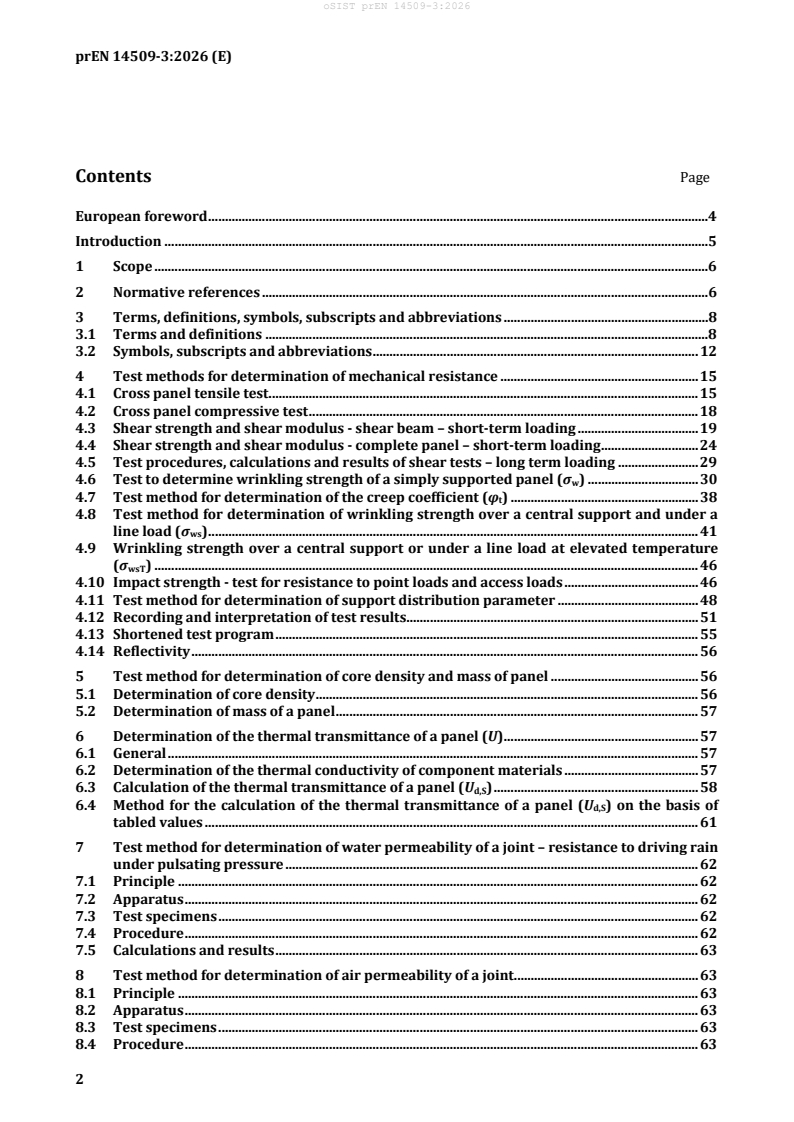
prEN 14509-3 is a draft European Standard from CEN for factory-made double skin metal faced insulating sandwich panels. It specifies test methods for determining mechanical strength, building physical behaviour and durability for panels used in roofs, external and internal walls, ceilings and cold store applications. The document also covers sampling, dimensional tolerances and testing for verification of constancy of performance (FPC).
What does prEN 14509-3 specify?
prEN 14509-3 specifies the test methods used to assess sandwich panels as products and as panel assemblies. Clause 4 to Clause 14 cover performance assessment, Clause 15 covers sampling, and Clause 16 covers FPC testing and follow-up rules.
The document is organized as follows:
| Annex | What it covers |
|---|---|
| Annex A | Replacement of Annexes A, B, C and D of EN 14509:2013 and a summary of the main changes |
| Annex B | Designations of the cross-sectional geometry of a sandwich panel with profiled faces |
In practice, this means the standard is a test and assessment document, not a design manual. A manufacturer or laboratory uses it to generate the data needed to describe panel performance.
What are the key requirements of prEN 14509-3?
Mechanical performance
Clause 4 gives the core test methods for mechanical resistance. It includes cross panel tensile and compressive tests, shear strength and shear modulus tests for short-term loading, long-term shear testing, wrinkling strength tests, creep coefficient determination, impact strength for point loads and access loads, and the support distribution parameter.
For readers, this is the part that tells you how the panel behaves when it is loaded in service. The results are used to assess strength, stiffness and time-dependent effects, so they matter for span selection, support spacing, fixing details and product declaration.
Clause 4.12 also sets out how to record and interpret test results, including characteristic values and interpolation or extrapolation of results. Clause 4.13 describes a shortened test program, which is useful when a full test set is not needed for every product variation.
Thermal, joint and acoustic performance
Clause 6 determines the thermal transmittance of a panel. It takes account of the core, the faces, the profile geometry and the thermal effect of the longitudinal joint, using calculation routes based on EN ISO 10211 and EN ISO 6946. Clause 6.4 also gives a tabulated-value method for steel-faced panels.
This matters because the thermal value is not just a material property of the core. The panel geometry and the joint can change the real heat flow, so the document tells the reader how to include those effects in the declared panel value.
Clauses 7 to 9 cover joints for water permeability under pulsating pressure, air permeability and water vapour permeability. These are the key enclosure tests for roofs and walls, especially where weather tightness or cold store performance is important.
Clauses 10 and 11 cover airborne sound insulation and sound absorption. The document links these results to standard acoustic ratings, so the panel can be described in terms that are usable for building specification.
Durability, fire and dimension control
Clause 12 addresses durability-related characteristics. It uses climatic ageing cycles called DUR1 and DUR2 and includes additional checks such as the wedge test, repeated loading, thermal shock and corrosion resistance. The choice of test depends on the core material and the bonding system.
In practice, this clause is about whether the panel keeps its performance after ageing, temperature change and moisture exposure. That is important for service life, especially for panel systems that depend on the bond between faces and core.
Clause 13 covers fire-related characteristics, including reaction to fire, resistance to fire, external fire performance for roofs, adhesive layer measurement and the propensity of the core material to undergo continuous smouldering. It also gives special mounting and fixing instructions for fire tests.
Clause 14 sets dimensional tolerances for panel thickness, flatness, profile depth, length, cover width, squareness, straightness, bowing, pitch of profile and widths of rib and valley. These limits matter because geometry affects fit, sealing, mechanical performance and installation quality.
Sampling and factory production control
Clause 15 gives sampling rules for assessment of performance. It requires simple random sampling, records of where and when the samples were taken, and test specimens taken from suitable positions across the panel width.
Clause 16 sets testing rules for verification of constancy of performance. It covers raw materials, components, non-complying products and modifications to the product or the factory production control system. For users, this is the part that links the laboratory test methods to production control in the factory.
What terms does prEN 14509-3 define?
- Sandwich panel - a building product with two metal faces on either side of a thermally insulating core, bonded so the three parts act compositely under load.
- Core - the insulating layer between the metal faces; the document notes that special edge details may use different core material if they do not affect mechanical performance.
- Joint - the interface where adjacent panels meet in the same plane, often including interlocking features that affect thermal, acoustic and fire performance.
- Product family - a group of products from one manufacturer for which results for one or more characteristics from one product are valid for the others in the range.
- Durability - the ability of the panel to withstand environmental effects and the related reduction in mechanical strength over time.
- Mineral wool (MW) - insulating wool made from molten stone, slag or glass.
- Rigid polyurethane (PU) - a rigid cellular thermoset insulation family, including PIR and PUR types.
Who uses prEN 14509-3?
prEN 14509-3 is used by sandwich panel manufacturers, testing laboratories, certification and technical assessment bodies, and factory production control teams. It is also used by specifiers, engineers, quality managers and buyers who need to compare products for roofs, walls, ceilings or cold store applications.
In practice, these users rely on the document to:
- plan product-type tests
- prepare test specimens and report results
- declare mechanical, thermal, acoustic, durability and fire-related performance
- verify consistency between batches and production lines
- support product descriptions for building applications
What changed in prEN 14509-3 from the previous edition?
prEN 14509-3:2026 supersedes EN 14509:2013. Annex A lists the main changes, including revised mechanical test clauses, expanded durability and fire-related provisions, a new chapter for water vapour permeability of a joint, and revised dimensional tolerance rules.
The update also includes changes to test procedures, calculations, figures and reporting rules across the document. For readers familiar with EN 14509:2013, Annex A is the quickest place to see where the methods were added, clarified or reworked.
Which standards are used with prEN 14509-3?
prEN 14509-3 relies on a broad set of companion standards for test methods, calculations and material specifications:
- EN 12865 and EN 12114 - water permeability and air permeability testing of joints
- EN ISO 12572 - water vapour transmission testing for joints
- EN ISO 10140-1, EN ISO 10140-2, EN ISO 717-1, EN ISO 354 and EN ISO 11654 - airborne sound insulation and sound absorption
- EN 1363-1, EN 1364-1, EN 1365-2, EN 13823, EN ISO 11925-2, EN 13501-1, EN 15254-5, EN 15254-7 and CEN/TS 1187 - fire testing, classification and extended application
- EN ISO 10211, EN ISO 6946 and EN ISO 10456 - thermal transmittance and thermal property calculations
- EN 13162, EN 13163, EN 13164, EN 13165 and EN 13166 - core material product standards
- EN 10169, EN 10346, EN 1396, EN 506 and EN 508-1 - metal sheet and coating specifications
- EN ISO 845, EN ISO 29470 and EN 1607 - density and tensile-related test methods for core materials
- ISO 12491 - statistical treatment of test results for characteristic values
- prEN 14509-5 - design methods that use the assessed panel data
- EN 1990-1, EN 1993-1-4 and EN 1999-1-1 - structural design basis and metal structure design context
These references matter because prEN 14509-3 often gives the sandwich-panel-specific procedure and then points to the companion standard for the test apparatus, rating method or calculation rule.
What does the prEN 14509-3 document contain?
The document contains detailed test procedures, calculation methods and reporting rules for the main performance areas of sandwich panels. It includes test set-ups for mechanical resistance, joint tightness, acoustics, durability and fire-related characteristics.
It also includes tables and figures for panel geometry, thermal bridge contribution factors, dimensional tolerances, mounting arrangements and interpretation of test results. Annex B is specifically for the geometry designations of profiled faces, which helps keep the mechanical and thermal descriptions consistent.
For practical use, the document provides the structure needed to test a panel, calculate the result, and report it in a way that can support product-type assessment and FPC.
Relations
- Effective Date
- 24-Jun-2026
Get Certified
Connect with accredited certification bodies for this standard

DIBt (Deutsches Institut für Bautechnik)
German Institute for Building Technology.
DIN CERTCO
DIN Group product certification.

Aboma Certification B.V.
Specialized in construction, metal, and transport sectors.
Sponsored listings
Frequently Asked Questions
prEN 14509-3 is a draft published by the European Committee for Standardization (CEN). Its full title is "Factory-made double skin metal faced insulating sandwich panels - Part 3: Test methods for determining mechanical strength, building physical behaviour and durability". This standard covers: This document specifies test methods needed for determination of mechanical strength, building physical behaviour and durability of factory-made double skin metal faced insulating sandwich panels (hereafter sandwich panels) for both self-supporting and structural applications in roofs, in external and internal walls (including partitions) and in ceilings in buildings as well as those in cold store applications.
This document specifies test methods needed for determination of mechanical strength, building physical behaviour and durability of factory-made double skin metal faced insulating sandwich panels (hereafter sandwich panels) for both self-supporting and structural applications in roofs, in external and internal walls (including partitions) and in ceilings in buildings as well as those in cold store applications.
prEN 14509-3 is classified under the following ICS (International Classification for Standards) categories: 91.100.60 - Thermal and sound insulating materials. The ICS classification helps identify the subject area and facilitates finding related standards.
prEN 14509-3 has the following relationships with other standards: It is inter standard links to EN 14509:2013. Understanding these relationships helps ensure you are using the most current and applicable version of the standard.
prEN 14509-3 is available in PDF format for immediate download after purchase. The document can be added to your cart and obtained through the secure checkout process. Digital delivery ensures instant access to the complete standard document.
Standards Content (Sample)
SLOVENSKI STANDARD
01-november-2026
Tovarniško izdelane izolacijske sendvič plošče z obojestranskim kovinskim
oplaščenjem - 3. del: Preskusne metode za ugotavljanje mehanske trdnosti,
fizičnega obnašanja stavb in vzdržljivosti
Factory-made double skin metal faced insulating sandwich panels - Part 3: Test methods
for determining mechanical strength, building physical behaviour and durability
Werkmäßig hergestellte Sandwich-Elemente mit beidseitigen Metalldeckschichten - Teil
3: Prüfverfahren zur Bestimmung der mechanischen Festigkeit, des bauphysikalischen
Verhaltens und der Dauerhaftigkeit
Panneaux sandwichs isolants à deux parements métalliques manufacturés - Partie 3 :
Méthodes d'essai pour déterminer la résistance mécanique, le comportement physique
des bâtiments et leur durabilité
Ta slovenski standard je istoveten z: prEN 14509-3
ICS:
91.100.60 Materiali za toplotno in Thermal and sound insulating
zvočno izolacijo materials
2003-01.Slovenski inštitut za standardizacijo. Razmnoževanje celote ali delov tega standarda ni dovoljeno.
DRAFT
EUROPEAN STANDARD
NORME EUROPÉENNE
EUROPÄISCHE NORM
August 2026
ICS 91.100.60 Will supersede EN 14509:2013
English Version
Factory-made double skin metal faced insulating sandwich
panels - Part 3: Test methods for determining mechanical
strength, building physical behaviour and durability
Panneaux sandwichs isolants à deux parements Werkmäßig hergestellte Sandwich-Elemente mit
métalliques manufacturés - Partie 3 : Méthodes d'essai beidseitigen Metalldeckschichten - Teil 3:
pour déterminer la résistance mécanique, le Prüfverfahren zur Bestimmung der mechanischen
comportement physique des bâtiments et leur Festigkeit, des bauphysikalischen Verhaltens und der
durabilité Dauerhaftigkeit
This draft European Standard is submitted to CEN members for enquiry. It has been drawn up by the Technical Committee
CEN/TC 128.
If this draft becomes a European Standard, CEN members are bound to comply with the CEN/CENELEC Internal Regulations
which stipulate the conditions for giving this European Standard the status of a national standard without any alteration.
This draft European Standard was established by CEN in three official versions (English, French, German). A version in any other
language made by translation under the responsibility of a CEN member into its own language and notified to the CEN-CENELEC
Management Centre has the same status as the official versions.
CEN members are the national standards bodies of Austria, Belgium, Bulgaria, Croatia, Cyprus, Czech Republic, Denmark, Estonia,
Finland, France, Germany, Greece, Hungary, Iceland, Ireland, Italy, Latvia, Lithuania, Luxembourg, Malta, Netherlands, Norway,
Poland, Portugal, Republic of North Macedonia, Romania, Serbia, Slovakia, Slovenia, Spain, Sweden, Switzerland, Türkiye and
United Kingdom.
Recipients of this draft are invited to submit, with their comments, notification of any relevant patent rights of which they are
aware and to provide supporting documentation.
Warning : This document is not a European Standard. It is distributed for review and comments. It is subject to change without
notice and shall not be referred to as a European Standard.
EUROPEAN COMMITTEE FOR STANDARDIZATION
COMITÉ EUROPÉEN DE NORMALISATION
EUROPÄISCHES KOMITEE FÜR NORMUNG
CEN-CENELEC Management Centre: Rue de la Science 23, B-1040 Brussels
© 2026 CEN All rights of exploitation in any form and by any means reserved Ref. No. prEN 14509-3:2026 E
worldwide for CEN national Members.
Contents Page
European foreword .4
Introduction .5
1 Scope .6
2 Normative references .6
3 Terms, definitions, symbols, subscripts and abbreviations .8
3.1 Terms and definitions .8
3.2 Symbols, subscripts and abbreviations . 12
4 Test methods for determination of mechanical resistance . 15
4.1 Cross panel tensile test . 15
4.2 Cross panel compressive test . 18
4.3 Shear strength and shear modulus - shear beam – short-term loading . 19
4.4 Shear strength and shear modulus - complete panel – short-term loading . 24
4.5 Test procedures, calculations and results of shear tests – long term loading . 29
4.6 Test to determine wrinkling strength of a simply supported panel (σ ) . 30
w
4.7 Test method for determination of the creep coefficient (φ ) . 38
t
4.8 Test method for determination of wrinkling strength over a central support and under a
line load (σ ) . 41
ws
4.9 Wrinkling strength over a central support or under a line load at elevated temperature
) . 46
(σwsT
4.10 Impact strength - test for resistance to point loads and access loads . 46
4.11 Test method for determination of support distribution parameter . 48
4.12 Recording and interpretation of test results . 51
4.13 Shortened test program . 55
4.14 Reflectivity . 56
5 Test method for determination of core density and mass of panel . 56
5.1 Determination of core density . 56
5.2 Determination of mass of a panel . 57
6 Determination of the thermal transmittance of a panel (U) . 57
6.1 General . 57
6.2 Determination of the thermal conductivity of component materials . 57
6.3 Calculation of the thermal transmittance of a panel (U ) . 58
d,S
6.4 Method for the calculation of the thermal transmittance of a panel (U ) on the basis of
d,S
tabled values . 61
7 Test method for determination of water permeability of a joint – resistance to driving rain
under pulsating pressure . 62
7.1 Principle . 62
7.2 Apparatus . 62
7.3 Test specimens . 62
7.4 Procedure . 62
7.5 Calculations and results . 63
8 Test method for determination of air permeability of a joint. 63
8.1 Principle . 63
8.2 Apparatus . 63
8.3 Test specimens . 63
8.4 Procedure . 63
8.5 Calculations and results . 63
9 Test method for determination of water vapour permeability of a joint . 63
9.1 Principle . 63
9.2 Apparatus . 63
9.3 Test specimens . 64
9.4 Procedure . 64
9.5 Calculations and results . 64
10 Test method for determination of airborne sound insulation . 64
10.1 Principle . 64
10.2 Apparatus . 64
10.3 Test specimens . 64
10.4 Procedure . 64
10.5 Calculations and results . 64
11 Test method for determination of sound absorption . 64
11.1 Principle . 64
11.2 Apparatus . 64
11.3 Test specimens . 65
11.4 Procedure . 65
11.5 Calculations and results . 65
12 Determination of durability related characteristics . 65
12.1 General . 65
12.2 Test DUR1 . 66
12.3 Test DUR2 . 68
12.4 Test report on durability tests DUR1 and DUR2 . 71
12.5 Adhesive bond between faces and prefabricated core material (wedge test) . 72
12.6 Repeated loading test . 74
12.7 Thermal shock test . 75
12.8 Corrosion resistance . 76
13 Determination of fire related characteristics . 78
13.1 Reaction to fire . 78
13.2 Resistance to fire . 85
13.3 Additional instructions for external fire performance for roofs . 94
13.4 Determination of the amount and thickness of the adhesive layer . 96
13.5 Test- and classification reports concerning reaction to fire and resistance to fire properties
.............................................................................................................................................................................. 97
13.6 Propensity to undergo continuous smouldering (for core material) . 100
14 Determination of dimensional tolerances . 100
14.1 General . 100
14.2 Dimensional tolerances . 101
15 Sampling . 109
16 Testing rules for verification of constancy of performance (FPC) . 110
16.1 General . 110
16.2 Raw material and components . 111
16.3 Non-complying products . 112
16.4 Procedure for modifications . 112
Annex A (informative) Replacement of Annexes A, B, C and D of EN 14509:2013 by this European
Standard . 113
Annex B (informative) Designations of the cross-sectional geometry of a sandwich panel with
profiled faces . 119
Bibliography . 120
European foreword
This document (prEN 14509-3:2026) has been prepared by Technical Committee CEN/TC 128 “Roof
covering products for discontinuous laying and products for wall cladding”, the secretariat of which is
held by NBN.
This document is currently submitted to the CEN Enquiry.
This document will supersede EN 14509:2013.
The main changes with respect to the previous edition are listed in Annex A.
Introduction
This document replaces Annexes A, B, C and D in EN 14509:2013. The testing procedures for
determination of assessment of performance are given in Clauses 4 to 14. The testing procedures for the
verification of constancy of performance (FPC) are given in Clause 16.
1 Scope
This document specifies test methods needed for determination of mechanical strength, building
physical behaviour and durability of factory-made double skin metal faced insulating sandwich panels
(hereafter sandwich panels) for both self-supporting and structural applications in roofs, in external
and internal walls (including partitions) and in ceilings in buildings as well as those in cold store
applications.
2 Normative references
The following documents are referred to in the text in such a way that some or all of their content
constitutes requirements of this document. For dated references, only the edition cited applies. For
undated references, the latest edition of the referenced document (including any amendments) applies.
EN 506:2008, Roofing products of metal sheet — Specification for self-supporting products of copper or
zinc sheet
EN 508-1:2021, Roofing and cladding products from metal sheet — Specification for self-supporting
products of steel, aluminium or stainless steel sheet — Part 1: Steel
EN ISO 29469:2022, Thermal insulating products for building applications — Determination of
compression behaviour (ISO 29469:2022)
EN 1363-1:2020, Fire resistance tests — Part 1: General requirements
EN 1364-1:2015, Fire resistance tests for non-loadbearing elements — Part 1: Walls
EN 1365-2:2014, Fire resistance tests for loadbearing elements — Part 2: Floors and roofs
EN 1396:2023, Aluminium and aluminium alloys — Coil coated sheet and strip for general applications —
Specifications
EN 1607:2013, Thermal insulating products for building applications — Determination of tensile strength
perpendicular to faces
EN 1990-1:2023+A1:2026, Eurocode — Basis of structural and geotechnical design — Part 1: New
structures
EN 1993-1-4:2025, Eurocode 3 — Design of steel structures — Part 1-4: Stainless steel structures
EN 1999-1-1:2023, Eurocode 9 — Design of aluminium structures — Part 1-1: General rules
EN 10169:2022, Continuously organic coated (coil coated) steel flat products — Technical delivery
conditions
EN 10346:2015, Continuously hot-dip coated steel flat products for cold forming — Technical delivery
conditions
EN 12085:2013, Thermal insulating products for building applications — Determination of linear
dimensions of test specimens
EN 12114:2000, Thermal performance of buildings — Air permeability of building components and
building elements — Laboratory test method
EN 12865:2001, Hygrothermal performance of building components and building elements —
Determination of the resistance of external wall systems to driving rain under pulsating air pressure
EN 13162:2012+A1:2015, Thermal insulation products for buildings — Factory made mineral wool (MW)
products — Specification
EN 13163:2012+A2:2016, Thermal insulation products for buildings — Factory made expanded
polystyrene (EPS) products — Specification
EN 13164:2012+A1:2015, Thermal insulation products for buildings — Factory made extruded
polystyrene foam (XPS) products — Specification
EN 13165:2012+A2:2016, Thermal insulation products for buildings — Factory made rigid polyurethane
foam (PU) products — Specification
EN 13166:2012+A2:2016, Thermal insulation products for buildings — Factory made phenolic foam (PF)
products — Specification
EN 13501-1:2018, Fire classification of construction products and building elements — Part 1:
Classification using data from reaction to fire tests
EN 13523-3:2024, Coil coated metals — Test methods — Part 3: Colour difference and metamerism —
Instrumental comparison
EN 13523-26:2022, Coil coated metals — Test methods — Part 26: Resistance to condensation of water
EN 13823:2020+A1:2022, Reaction to fire tests for building products — Building products excluding
floorings exposed to the thermal attack by a single burning item
prEN 14509-5:2026, Factory made double skin metal faced insulating sandwich panels — Part 5: Design
methods. Determination criteria for combing actions and spans
EN 15254-5:2018, Extended application of results from fire resistance tests — Non-loadbearing walls —
Part 5: Metal sandwich panel construction
EN 15254-7:2018, Extended application of results from fire resistance tests — Non-loadbearing ceilings
— Part 7: Metal sandwich panel construction
EN ISO 354:2003, Acoustics — Measurement of sound absorption in a reverberation room (ISO 354:2003)
EN ISO 717-1:2020, Acoustics — Rating of sound insulation in buildings and of building elements — Part
1: Airborne sound insulation (ISO 717-1:2020)
EN ISO 845:2009, Cellular plastics and rubbers — Determination of apparent density (ISO 845:2006)
EN ISO 4628-2:2016, Paints and varnishes — Evaluation of degradation of coatings — Designation of
quantity and size of defects, and of intensity of uniform changes in appearance — Part 2: Assessment of
degree of blistering (ISO 4628-2:2016)
EN ISO 6892-1, Metallic materials — Tensile testing — Part 1: Method of test at room temperature (ISO
6892-1:2019)
EN ISO 6946:2017, Building components and building elements — Thermal resistance and thermal
transmittance — Calculation methods (ISO 6946:2017, Corrected version 2021-12)
EN ISO 10140-1:2021, Acoustics — Laboratory measurement of sound insulation of building elements —
Part 1: Application rules for specific products (ISO 10140-1:2021)
EN ISO 10140-2:2021, Acoustics — Laboratory measurement of sound insulation of building elements —
Part 2: Measurement of airborne sound insulation (ISO 10140-2:2021)
EN ISO 10211:2017, Thermal bridges in building construction — Heat flows and surface temperatures —
Detailed calculations (ISO 10211:2017)
EN ISO 10456:2007, Building materials and products — Hygrothermal properties -Tabulated design
values and procedures for determining declared and design thermal values (ISO 10456:2007)
EN ISO 11654:1997, Acoustics — Sound absorbers for use in buildings — Rating of sound absorption (ISO
11654:1997)
EN ISO 11925-2:2026, Reaction to fire tests — Ignitability of products subjected to direct impingement of
flame — Part 2: Single-flame source test (ISO 11925-2:2026)
EN ISO 12572:2016, Hygrothermal performance of building materials and products — Determination of
water vapour transmission properties — Cup method (ISO 12572:2016)
EN ISO 29470:2020, Thermal insulating products for building applications — Determination of the
apparent density (ISO 29470:2020)
ISO 12491:1997, Statistical methods for quality control of building materials and components
CEN/TS 1187:2012, Test methods for external fire exposure to roofs
3 Terms, definitions, symbols, subscripts and abbreviations
3.1 Terms and definitions
For the purposes of this document, the following terms, definitions, symbols, subscripts and
abbreviations apply.
3.1.1
assembly
connected panels with joints as their intrinsic parts
3.1.2
bending moment capacity
maximum bending moment recorded during a test on an individual panel
3.1.3
bending resistance
characteristic value of bending moment capacity determined on the basis of a test series
3.1.4
bond
bonding
adhesion between the face(s) and the core normally provided by an adhesive
3.1.5
auto-adhesive bond
self-adhesion of the core to the face(s) occurring automatically without the use of an adhesive
Note 1 to entry: This technique is used for producing sandwich panels by foaming.
3.1.6
ceiling
covering over an internal area
3.1.7
core
layer of material, having thermal insulating properties, which is bonded between two metal faces
Note 1 to entry: Panels with special edge details in the longitudinal joints may utilize different core materials from
the main insulating core (e.g. for improved fire performance) if these edge details have no influence on the
mechanical performance of the panel.
3.1.8
mineral wool
MW
insulating wool produced from molten stone, slag or glass
[SOURCE: EN 13162:2012+A1:2015]
3.1.9
phenolic foam
PF
rigid cellular foam, the polymer structure of which is made primarily from the polycondensation of
phenol, its homologues and/or derivatives, with or without aldehydes or ketones
[SOURCE: EN 13166:2012+A2:2016]
3.1.10
expanded polystyrene
EPS
rigid cellular plastic material, manufactured by moulding beads or granules of expandable polystyrene
or one of its copolymers, with an air filled closed cellular structure
[SOURCE: EN 13163:2012+A2:2016]
3.1.11
extruded polystyrene foam
XPS
rigid cellular plastics insulation material expanded and extruded with or without a skin, from
polystyrene or one of its copolymers and which has a closed cell structure
[SOURCE: EN 13164:2012+A1:2015]
3.1.12
rigid polyurethane
PU
family of rigid cellular thermoset polymeric insulation products with a substantially closed cell structure
including both polymer types based on PIR and PUR
[SOURCE: EN 13165:2012+A2:2016]
3.1.13
durability
ability of the panel to withstand the environmental effects and accommodate the consequent decrease
in mechanical strength with time caused by factors such as temperature, humidity, freeze-thaw cycles
and their various combinations
3.1.14
edge
longitudinal edge
side of the panel where adjacent panels join together in the same plane
3.1.15
face
flat, lightly profiled or profiled thin metal sheet firmly bonded to the core
3.1.16
flat face
face without any rolled or pressed profile, or raised strengthening rib
3.1.17
lightly profiled face
face with a rolled or pressed profile not exceeding 5 mm in depth
3.1.18
profiled face
face with a rolled or pressed profile exceeding 5 mm in depth
3.1.19
incompletely bonded face
metal face whose bond to the core is adequate for sandwich action but does not include the entire
surface of the core
Note 1 to entry: An example is a trapezoidally profiled face that has voids between the raised profiles and the core.
3.1.20
fastener
component (screw incl. washer, with or without sealant if relevant) used for fixing the panel to the
supporting structure
3.1.21
fixing
mechanical connection between the sandwich panel and the supporting structure, typically with one
fastener or more fasteners in a visible fixing (through the sandwich panel) or in a hidden fixing (placed
in the longitudinal joint of the sandwich panel)
Note 1 to entry: Fixing is covering only the failure modes in sandwich panels caused by the fastening.
3.1.22
hidden fixing
mechanical connection between the sandwich panel and the supporting structure, placed in the
longitudinal joint of adjacent sandwich panels consisting of one or more fasteners (with or without
washer) going through or connecting both sheets in a certain arrangement in relation to the sandwich
panel geometry, with or without load spreading component
3.1.23
visible fixing
one or more fasteners in a certain minimum distance to the sandwich panel edges and between
themselves (if applicable), visible on the visible side of the face of the sandwich panel, penetrating the
inner and the outer face and the core of the sandwich panel
Note 1 to entry: Visible fixings can be covered by flashings after installation.
3.1.24
incompletely bonded panel
panel in which one or both faces is incompletely bonded
3.1.25
joint
interface between two panels where the meeting edges have been designed to allow the panels to join
together in the same plane
Note 1 to entry: The joint may incorporate interlocking parts that enhance the mechanical properties of the
system as well as improve the thermal, acoustic and fire performance and restrict air movement.
Note 2 to entry: The term ‘joint’ does not refer to a junction between cut panels or a junction where the panels are
not installed in the same plane.
3.1.26
lamella
core material consisting of mineral wool that has been cut and orientated with the fibres perpendicular
to the faces prior to bonding
3.1.27
pre-manufactured
pre-formed
component or material that is supplied for panel production ready for direct incorporation into the
sandwich panel
3.1.28
product family
group of products produced by one manufacturer for which the assessment results for one or more
characteristics from any one product within the range are valid for all other products within this range
3.1.29
sandwich panel
building product consisting of two metal faces positioned on either side of a core that is a thermally
insulating material, which is firmly bonded to both faces so that the three components act compositely
when under load
3.1.30
shift
period of production during a working day, normally 6 h to 8 h but can be less
3.1.31
side lap
folded area of one or both of the face materials along the longitudinal edge of the panel which engages
with the adjacent panel to form an interlocking or overlapping joint
3.1.32
wrinkling strength
strength representing the characteristic value of wrinkling stress
3.1.33
wrinkling stress
stress in the compressed face of a panel undergoing loading in bending at the moment of failure load
3.2 Symbols, subscripts and abbreviations
For the purposes of this document, the following symbols, subscripts and abbreviations apply.
3.2.1 Symbols
A cross-sectional area (may be full width of panel or per unit width)
B flexural rigidity (may be full width of panel or per unit width),
overall width of the panel/specimen,
C ratio
D overall thickness of the panel
E modulus of elasticity
F force,
load,
support reaction
G shear modulus,
permanent action
I moment of inertia
L span,
distance,
width of support (L )
s
M bending moment
N axial compressive force
Q variable action
R resistance,
sound reduction index (R ),
w
reflectivity (R ),
G
tensile strength (R , R )
DUR 24
S shear rigidity
T temperature
U thermal transmittance,
thermal transmittance including the influence of the joints U
d,s
V shear force
a distance apart of clips (6.4)
b width of test specimen,
width of plate,
width of ribs/valleys,
bowing
d depth of face profile or stiffeners,
depth of core (d )
C
e distance between centroids of faces,
base of natural logarithms (e = 2,718 282)
f strength,
yield stress,
thermal transmittance contribution factor (f )
joint
h height of profile,
thickness (e.g. glue),
thickness of test specimen
k parameter (4.11.5.2 support reaction capacity),
correction factor
l length,
deviation
m mass
n number of tests,
number of screws,
number of webs
p pitch of profile
q live load
r radius
s length of web (s )
w1
t thickness of face sheet
v variance factor
w deflection,
displacement,
compression,
cover width
x, y, z coordinates
α parameter (4.6.5.4),
coefficient of thermal expansion, sound absorption (α ),
w
ratio (4.4.5.3)
β parameter (4.6.5.4)
δ deviation
ϕ angle
γ shear strain, partial safety factor
λ thermal conductivity, λ (design value), ratio (4.4.5.3)
design
φ creep coefficient
σ wrinkling strength, standard deviation
τ shear stress
ρ coefficient,
density
3.2.2 Subscripts
C core
D expressed value (R , λ )
D D
F face,
action (γ )
F
G self-weight, degree
M material (γ )
M
Q variable action
S sandwich,
sandwich part of the cross-section
adj adjusted
b bending, elastic extension
c compression,
carrier (13.4.2.3),
clip (f )
joint,c
d design
e external,
additional thickness of main profiles (Δe)
eff effective
f load, face (λ )
fi
i internal (λfi)
i, j index
k characteristic value
lin linear
m material
nom nominal
nc without clip (f )
joint,nc
obs observed (e.g. result)
q uniform load
s support (L = support width),
s
stiffeners,
surface (R )
s1
t tension,
time,
thickness relevant for measuring the tolerances
tol tolerance
tr traffic (C )
tr
u ultimate (F )
u
v shear, variance
w wind,
web,
wrinkling (σ ),
w
weighted (R )
w
y yield
0 basic value,
unit width,
time (e.g. t = 0)
1 outer face,
top face
2 inner face,
bottom face
3.2.3 Abbreviations
CWT classified without testing
EPS expanded polystyrene
FPC factory production control
MW mineral wool
PCS gross calorific potential
PU rigid polyurethane foam (PU includes polyisocyanurate foam (PIR))
PF phenolic foam
XPS extruded polystyrene foam
4 Test methods for determination of mechanical resistance
4.1 Cross panel tensile test
4.1.1 Principle
This test measures the cross panel tensile strength and the E-modulus of the core material.
The mean and characteristic value of the cross panel tensile strength and the mean and characteristic
value of E-modulus shall be determined in accordance with EN 1607:2013, Clause 4 and the following
sub clauses.
If not specified otherwise in this standard, conditioning of test specimens shall be carried out at
(23 ± 5) °C for at least 6 h. Tests shall be carried out at (23 ± 5) °C.
4.1.2 Apparatus
The tensile test apparatus shall be in accordance with EN 1607:2013, Clause 5.
4.1.3 Test specimens
The test shall be performed with the faces of the panel intact (in place) in order to include the tensile
bond strength between the faces and the core or to demonstrate adequate bond.
For panels with profiled faces the specimens shall be cut from the predominant thickness (see examples
in Figure 1).
Figure 1 — Cutting of specimens
Test specimens shall be of square cross-section having side dimensions between 100 mm and 300 mm.
Where applicable the test specimen shall include the full width of lamellas.
For incompletely bonded panels, the specimens shall be cut from the fully bonded part of the cross-
section (see the right-hand example in Figure 1).
The dimensions of the specimen shall be measured in accordance with EN 12085:2013, Clause 7. The
tolerance on side dimension shall be ±3 mm. Those samples that show evidence of delamination caused
by the cutting process are rejected (up to a maximum of 30 % of those cut for any family of tests).
NOTE 1 Test specimens are very sensitive to the process of cutting and the accuracy of testing in particular for
tensile test measurements. Considerable care is needed in the cutting process, especially if the core material is
relatively weak or has brittle tendencies. The cutting can be carried out with a band saw with a fine-toothed blade.
It can be advantageous to sandwich the specimen between two pieces of plywood or similar material in order to
reduce vibration during the cutting process. It is suggested that specimens will be carefully inspected after cutting.
Where it is not possible to cut a specimen with two plain faces, due to the profile of the faces, the
specimen shall be prepared with an appropriately shaped filling piece, which is glued to the profiled face
(see examples in Figure 2). In this case the mean value of the specimen thickness is used in Formula (2)
for determination of the tensile E modulus and in Formula (4) for determination of the compression
modulus.
Additional thin layers may be adhered to the faces in order to ensure that the loading platens of the
testing machine are parallel at the commencement of the tensile test.
NOTE 2 As an alternative to the use of shaped filling pieces and if the shape of the profiled face is suitable, it can
be possible to glue two specimens together in such a way that the profiled faces mate.
Figure 2 — Examples of specimens with shaped filling pieces
4.1.4 Procedure
The test shall be carried out by loading the specimen continuously, or in at least 10 increments, using a
tensile testing machine. The deflection rate shall have a minimum value of 1 % of h per minute and shall
not exceed 3 % of h per minute. During the test the deflection shall be measured with a precision of
0,01 mm and the force with a precision of 10 N. A load-deflection curve shall be drawn (see
Figure 3).The test shall be continued until the ultimate load (F ) is reached (Figure 3). If the specimen
u
does not exhibit a clearly identified ultimate load the test shall be discontinued when the relative
deformation exceeds 20 %.
4.1.5 Calculations and results
4.1.5.1 General
Recording and interpretation of test results shall comply with 4.12.
The test report shall give the characteristic and mean value (4.12.2) for tensile strength and shall state
the failure mode, i.e. whether failure was in the adhesion layer or in the core. The test report shall also
give the characteristic and mean value of cross panel tensile E-modulus.
4.1.5.2 Cross panel tensile strength (f )
Ct
The tensile strength shall be calculated as follows.
The tensile strength f is given by Formula (1):
Ct
F
u
f = (1)
Ct
A
where
F is the ultimate load;
u
A is the cross-sectional area of the specimen determined from the measured dimensions.
NOTE 1 For specimens that do not exhibit a clear ultimate load, F can alternatively be specified as the load at
u
a specified relative deformation. For polyurethane foams, 10 % relative deformation (0,1 h) can be an appropriate
limit. For materials with a more rigid cell structure or of non-cellular structure, a lower value can be used.
Figure 3 — Load against deflection curve (F against displacement ‘w’)
U
NOTE 2 Special attention is given in cases where the failure is close to the adhesion layer to determine the
location of the failure.
4.1.5.3 Cross panel tensile modulus (E )
Ct
The tensile modulus E is given by Formula (2) and calculated from the linear part of the load-tension
Ct
curve, preferable between the load points of approximately 20 % and 50 % of the ultimate load:
F h
u
E = (2)
Ct
w A
u
where
F is the ultimate load;
u
h is the thickness of the test specimen determined from the centre of faces ;
w is the ideal displacement at ultimate load based on the linear part of the curve as shown in
u
Figure 3;
A is the cross-sectional area of the specimen determined from the measured dimensions.
4.1.5.4 Cross panel tensile strength and modulus at elevated temperature
o o
For determination of cross panel tensile strength fCt,+80 C and modulus ECt,+80 C at elevated temperature,
the test described in 4.1.1 to 4.1.5 shall also be carried out on specimens which have been heated for 20
h to 24 h in a heating chamber at a temperature of 80 °C. The tensile test shall be carried out
immediately, before the specimen has cooled. If the application requires different temperatures the
preconditioning and testing can also be performed at this temperature if specimens have been heated
for 20 h to 24 h in a heating chamber.
The test is recommended to be carried out by heating the specimens together with the load distributing
platens to a temperature of max. 85 °C and then carrying out immediately the tensile test. .
The characteristic and mean value for the cross panel tensile strength and E-modulus at elevated
temperature shall be added to the test report. The test results are used to determine the wrinkling
strength at elevated temperature (4.9)
4.2 Cross panel compressive test
4.2.1 Principle
This test measures the compressive strength and E-modulus in compression.
The mean value and the characteristic value of the compressive strength and the E-modulus shall be
determined in accordance with EN ISO 29469:2022, Clause 4 and the following sub clauses.
If not specified otherwise in this standard, conditioning of test specimens shall be carried out at
(23 ± 5) °C for at least 6 h. Tests shall be carried out at (23 ± 5) °C.
4.2.2 Apparatus
The apparatus shall be in accordance with EN ISO 29469:2022, Clause 5.
4.2.3 Test specimens
Test specimens shall be prepared as described in 4.1.3. If filling pieces are needed because of the profile
of face(s) then these shall not be glued to the loading plates.
4.2.4 Procedure
The specimen shall be placed between the two parallel stiff loading plates of a compression testing
machine. The deflection rate shall have a minimum value of 1 % of h per minute and shall not exceed
3 % of h per minute. During the test the deflection shall be measured with a precision of 0,01 mm and
the force with a precision of 10 N. A load-deflection curve shall be drawn (see Figure 3).
4.2.5 Calculations and results
4.2.5.1 General
Recording and interpretation of test results shall comply with 4.12.
The test report shall give the characteristic and mean value (4.12.2) for compression s
...