

prEN 16120
(Main)Child care articles - Chair mounted seat
- Abstract
This document specifies safety requirements and test methods for chair mounted seats intended to be positioned on an adult chair to raise the sitting position of a child able to sit unaided up to an age of 36 months or a maximum weight of 15 kg.
This document does not apply to cushions, pads and products only aimed at restraining the child on a chair without raising the child's sitting position.
This document does not apply to chair mounted seats designed for children with special needs, and/or which fall under the scope of Regulation (EU) 2017/745 (medical devices).
If a chair mounted seat has several functions or can be converted into another function, the relevant European Standards can apply.
- Status
- Not Published
- Publication Date
- 12-Jul-2028
- Technical Committee
- CEN/TC 252 - Child use and care articles
- Drafting Committee
- CEN/TC 252/WG 1 - Seating and body care
- Current Stage
- 4020 - Submission to enquiry - Enquiry
- Start Date
- 12-Nov-2026
- Due Date
- 01-Apr-2027
- Completion Date
- 12-Nov-2026

prEN 16120 is a CEN draft European Standard for child care articles - chair mounted seat. It specifies safety requirements and test methods for chair mounted seats positioned on an adult chair to raise the sitting position of a child able to sit unaided up to 36 months or a maximum weight of 15 kg. It is written for manufacturers, test laboratories, importers and product safety teams that need a common basis for design, testing and product information.
What does prEN 16120 specify?
prEN 16120 covers the safety of chair mounted seats used on an adult chair, together with the tests used to check them. It focuses on the product itself and on the information supplied with it, so readers can see both how the seat is tested and what must be communicated to users.
The scope excludes cushions, pads and products that only restrain the child without raising the sitting position. It also excludes chair mounted seats designed for children with special needs and products within the scope of Regulation (EU) 2017/745 on medical devices. If a chair mounted seat has more than one function or can be converted to another function, the relevant European Standards can apply.
The document is organized into these main parts: scope, normative references, terms and definitions, test equipment, general test conditions, chemical hazards, thermal hazards, mechanical hazards, and product information.
| Annex | What it covers |
|---|---|
| Annex A | Rationale for selected requirements and test choices |
| Annex ZA | Relationship with EU safety requirements and presumption of conformity |
What are the key requirements of prEN 16120?
prEN 16120 combines preparation rules, safety tests and marking requirements. In practice, the document checks that the chair mounted seat is safe when assembled, resists realistic loads, does not trap or injure a child, and gives clear warnings and sizing information.
Test conditions and preparation
Clause 5 requires products to be tested fully assembled and ready for use, with fabrics cleaned or washed and dried twice according to the manufacturer’s instructions. The sample is conditioned before testing, and the tests are carried out at controlled temperature.
This matters because the product is checked in the form a buyer or parent actually uses. If the chair mounted seat can be assembled or adjusted in different ways, the most onerous combination is used for each test, so the weakest practical configuration is covered.
Clause 5 also sets the order of test and the tolerance rules for force, mass, dimensions, angle and duration. That gives laboratories a repeatable way to run the tests and compare results.
Chemical and thermal safety
Clause 6 requires the migration of elements from materials on exterior surfaces to comply with EN 17826:2025, and textile components to meet the relevant textile requirements in the same standard. This means materials in contact with the child are checked for chemical hazards that matter in mouthing and skin contact.
Clause 7 covers thermal hazards by requiring textiles, coated textile supports and plastic coverings to meet flammability checks based on EN 71-2:2020+A1:2025. The practical result is that soft and covered parts are assessed for how they ignite and spread flame.
Mechanical safety
Clause 8 is the main safety section. It requires locking mechanisms for height adjustment or folding, automatic engagement when deployed, and protection against unintentional release. If the product uses inflatable systems, non-return valves are required.
Clause 8 also checks for finger and head entrapment, moving-part hazards, entanglement, choking, aspiration, insertion and ingestion risks, suffocation hazards, hazardous edges, and structural integrity. These tests use specific probes, gauges and small-part checks so that openings, gaps and detachable parts are evaluated in a practical way.
The structural tests are especially important. Clause 8.8 uses static and dynamic loading to check that the chair mounted seat keeps its intended function, does not collapse, and does not change height position. This is the part that shows whether the product can take long-term loading and repeated impacts without failure.
Falling protection and chair fit
Clause 8.9 requires an adjustable chair attachment system that fixes the seat to both the backrest and the seat surface of the adult chair. The attachment system and the restraint system are tested for strength and slippage, so the product stays secured in use.
The restraint system must be adjustable to the child and include at least a waist restraint and a crotch restraint. The child must not be able to use the restraint system without the crotch restraint, which matters because the restraint has to keep the child properly positioned.
Clause 8.9.3 requires lateral protections. If the lateral protections are non-rigid, the product is not suitable for children under 18 months, and the age suitability must be stated in the user information. Clause 8.9.4 links the product to the size of the adult chair, so the supplied dimensions and the actual attachment geometry have to match.
Product information
Clause 9 requires marking, purchase information and instructions for use. The markings include the manufacturer or importer identification, the product identification, and visible warnings such as “Never leave the child unattended,” together with the relevant graphical symbols.
The purchase information and instructions must include the intended age range, weight limit, compatible chair dimensions, safe assembly and use, warnings about restraint and attachment systems, and advice not to use stools or benches. That helps the user choose a suitable chair and use the product in a way that matches the tested design.
What terms does prEN 16120 define?
- chair attachment system - the system designed to attach the chair mounted seat to the adult chair.
- restraint system - the system used to restrain the child within the chair mounted seat.
- waist restraint - the part of the restraint system that restrains the child in the waist area.
- crotch restraint - the part of the restraint system that fits between the child’s legs.
- locking device - a mechanical component that maintains parts of the product in the position of use and can be activated or deactivated by the operating device.
- operating device - the part of the locking mechanism designed to be activated by the carer through one or more positive actions.
- locking mechanism - the assembly made up of one or more locking devices and one or more operating devices.
Who uses prEN 16120?
prEN 16120 is used by manufacturers and designers of child care articles who need to build chair mounted seats to a defined safety level. It is also used by quality managers, test laboratories and conformity assessment teams that check chemical, thermal and mechanical safety.
Importers, distributors and buyers use it to understand the product information, warnings and chair-size limits that must accompany the product. Retail and compliance teams also use it when reviewing whether a chair mounted seat is suitable for the intended age range and adult chair dimensions.
What changed in prEN 16120 from the previous edition?
prEN 16120 will supersede EN 16120:2012+A2:2016.
Which standards are used with prEN 16120?
| Standard | What it contributes |
|---|---|
| EN 71-2:2020+A1:2025 | Flammability test methods for textiles, coated textile supports and plastic coverings |
| EN 17826:2025 | Chemical hazard requirements, including migration of elements and textile component requirements |
| EN ISO 2439:2008 | Hardness method used to specify the test foam |
The bibliography also cites CEN/TS 13387-1:2025 to CEN/TS 13387-5:2025 as background on safety philosophy, chemical hazards, mechanical hazards, thermal hazards and product information.
What does the prEN 16120 document contain?
The document contains detailed test equipment definitions for probes, gauges, a small parts cylinder, a torso probe, a test beam, a test sphere, a test mass and a loading pad. It also includes step-by-step test methods for finger entrapment, head entrapment, moving parts, cords and loops, small parts, filling material accessibility, packaging suffocation risk, marking durability, static strength, dynamic strength, attachment-system strength, restraint-system strength, lateral protections and chair-size checks.
Several figures show the geometry and use of the probes and test set-ups, including the lateral-protection tests and the size checks for adult chairs. Annex A explains the safety reasons behind the requirements, and Annex ZA gives the correspondence between the standard and the EU safety requirements it is intended to cover.
Relations
- Effective Date
- 20-May-2026
Frequently Asked Questions
prEN 16120 is a draft published by the European Committee for Standardization (CEN). Its full title is "Child care articles - Chair mounted seat". This standard covers: This document specifies safety requirements and test methods for chair mounted seats intended to be positioned on an adult chair to raise the sitting position of a child able to sit unaided up to an age of 36 months or a maximum weight of 15 kg. This document does not apply to cushions, pads and products only aimed at restraining the child on a chair without raising the child's sitting position. This document does not apply to chair mounted seats designed for children with special needs, and/or which fall under the scope of Regulation (EU) 2017/745 (medical devices). If a chair mounted seat has several functions or can be converted into another function, the relevant European Standards can apply.
This document specifies safety requirements and test methods for chair mounted seats intended to be positioned on an adult chair to raise the sitting position of a child able to sit unaided up to an age of 36 months or a maximum weight of 15 kg. This document does not apply to cushions, pads and products only aimed at restraining the child on a chair without raising the child's sitting position. This document does not apply to chair mounted seats designed for children with special needs, and/or which fall under the scope of Regulation (EU) 2017/745 (medical devices). If a chair mounted seat has several functions or can be converted into another function, the relevant European Standards can apply.
prEN 16120 is classified under the following ICS (International Classification for Standards) categories: 97.140 - Furniture; 97.190 - Equipment for children. The ICS classification helps identify the subject area and facilitates finding related standards.
prEN 16120 has the following relationships with other standards: It is inter standard links to EN 16120:2012+A2:2016. Understanding these relationships helps ensure you are using the most current and applicable version of the standard.
prEN 16120 is associated with the following European legislation: EU Directives/Regulations: 2023/988/EU; Standardization Mandates: M/527, M/627, M/XXX. When a standard is cited in the Official Journal of the European Union, products manufactured in conformity with it benefit from a presumption of conformity with the essential requirements of the corresponding EU directive or regulation.
prEN 16120 is available in PDF format for immediate download after purchase. The document can be added to your cart and obtained through the secure checkout process. Digital delivery ensures instant access to the complete standard document.
Standards Content (Sample)
SLOVENSKI STANDARD
01-december-2026
Izdelki za otroke - Otroški sedeži, ki se pritrdijo na stol
Child care articles - Chair mounted seat
Artikel für Säuglinge und Kleinkinder - Sitzerhöhungen für Stühle
Articles de puériculture - Rehausseurs de chaise
Ta slovenski standard je istoveten z: prEN 16120
ICS:
97.140 Pohištvo Furniture
97.190 Otroška oprema Equipment for children
2003-01.Slovenski inštitut za standardizacijo. Razmnoževanje celote ali delov tega standarda ni dovoljeno.
DRAFT
EUROPEAN STANDARD
NORME EUROPÉENNE
EUROPÄISCHE NORM
November 2026
ICS 97.190; 97.140 Will supersede EN 16120:2012+A2:2016
English Version
Child care articles - Chair mounted seat
Articles de puériculture - Rehausseurs de chaise Artikel für Säuglinge und Kleinkinder - Sitzerhöhungen
für Stühle
This draft European Standard is submitted to CEN members for enquiry. It has been drawn up by the Technical Committee
CEN/TC 252.
If this draft becomes a European Standard, CEN members are bound to comply with the CEN/CENELEC Internal Regulations
which stipulate the conditions for giving this European Standard the status of a national standard without any alteration.
This draft European Standard was established by CEN in three official versions (English, French, German). A version in any other
language made by translation under the responsibility of a CEN member into its own language and notified to the CEN-CENELEC
Management Centre has the same status as the official versions.
CEN members are the national standards bodies of Austria, Belgium, Bulgaria, Croatia, Cyprus, Czech Republic, Denmark, Estonia,
Finland, France, Germany, Greece, Hungary, Iceland, Ireland, Italy, Latvia, Lithuania, Luxembourg, Malta, Netherlands, Norway,
Poland, Portugal, Republic of North Macedonia, Romania, Serbia, Slovakia, Slovenia, Spain, Sweden, Switzerland, Türkiye and
United Kingdom.
Recipients of this draft are invited to submit, with their comments, notification of any relevant patent rights of which they are
aware and to provide supporting documentation.
Warning : This document is not a European Standard. It is distributed for review and comments. It is subject to change without
notice and shall not be referred to as a European Standard.
EUROPEAN COMMITTEE FOR STANDARDIZATION
COMITÉ EUROPÉEN DE NORMALISATION
EUROPÄISCHES KOMITEE FÜR NORMUNG
CEN-CENELEC Management Centre: Rue de la Science 23, B-1040 Brussels
© 2026 CEN All rights of exploitation in any form and by any means reserved Ref. No. prEN 16120:2026 E
worldwide for CEN national Members.
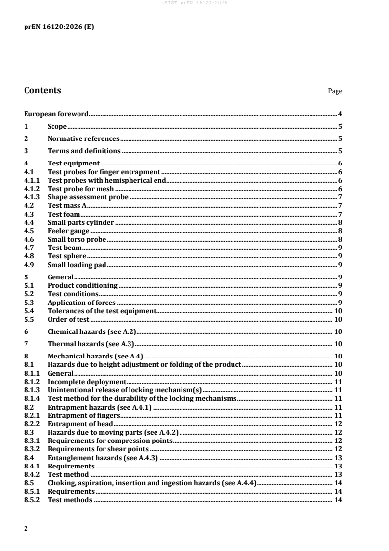
Contents Page
European foreword . 4
1 Scope . 5
2 Normative references . 5
3 Terms and definitions . 5
4 Test equipment . 6
4.1 Test probes for finger entrapment . 6
4.1.1 Test probes with hemispherical end . 6
4.1.2 Test probe for mesh . 6
4.1.3 Shape assessment probe . 7
4.2 Test mass A . 7
4.3 Test foam . 7
4.4 Small parts cylinder . 8
4.5 Feeler gauge . 8
4.6 Small torso probe . 8
4.7 Test beam . 9
4.8 Test sphere . 9
4.9 Small loading pad . 9
5 General . 9
5.1 Product conditioning . 9
5.2 Test conditions . 9
5.3 Application of forces . 9
5.4 Tolerances of the test equipment . 10
5.5 Order of test . 10
6 Chemical hazards (see A.2) . 10
7 Thermal hazards (see A.3) . 10
8 Mechanical hazards (see A.4) . 10
8.1 Hazards due to height adjustment or folding of the product . 10
8.1.1 General . 10
8.1.2 Incomplete deployment . 11
8.1.3 Unintentional release of locking mechanism(s) . 11
8.1.4 Test method for the durability of the locking mechanisms . 11
8.2 Entrapment hazards (see A.4.1) . 11
8.2.1 Entrapment of fingers . 11
8.2.2 Entrapment of head . 12
8.3 Hazards due to moving parts (see A.4.2) . 12
8.3.1 Requirements for compression points . 12
8.3.2 Requirements for shear points . 12
8.4 Entanglement hazards (see A.4.3) . 13
8.4.1 Requirements . 13
8.4.2 Test method . 13
8.5 Choking, aspiration, insertion and ingestion hazards (see A.4.4) . 14
8.5.1 Requirements . 14
8.5.2 Test methods . 14
8.6 Suffocation hazards (see A.4.5) . 16
8.6.1 Plastic packaging . 16
8.6.2 Plastic decals . 16
8.7 Hazardous edges, corners and protruding parts (see A.4.6) . 16
8.8 Hazards from inadequate structural integrity (see A.4.7) . 16
8.8.1 Static strength . 16
8.8.2 Dynamic strength . 17
8.9 Hazards from falling . 17
8.9.1 Chair attachment systems . 17
8.9.2 Restraint system . 18
8.9.3 Lateral protections (see A.4.8.1) . 19
8.9.4 Hazards due to inadequate size (see A.4.8.2) . 22
9 Product information . 25
9.1 General . 25
9.2 Marking . 26
9.2.1 Requirements . 26
9.2.2 Durability of marking . 27
9.2.3 Test method for durability of marking . 27
9.3 Purchase information . 27
9.4 Instructions for use . 28
Annex A (informative) Rationales . 30
A.1 Introduction. 30
A.2 Chemical hazards (see Clause 6) . 30
A.3 Thermal hazards (see Clause 7) . 30
A.4 Mechanical hazards (see Clause 8) . 30
A.4.1 Entrapment hazards (see 8.2) . 30
A.4.2 Hazards due to moving parts (see 8.3) . 31
A.4.3 Entanglement hazards (see 8.4) . 31
A.4.4 Choking, aspiration, insertion and ingestion hazards (see 8.5) . 31
A.4.5 Suffocation hazards (see 8.6) . 31
A.4.6 Hazardous edges, corners and protruding parts (see 8.7) . 31
A.4.7 Hazards from inadequate structural integrity (see 8.8) . 31
A.4.8 Hazards from falling (see 8.9) . 32
Bibliography . 36
European foreword
This document (prEN 16120:2026) has been prepared by Technical Committee CEN/TC 252 “Child use
and care articles”, the secretariat of which is held by AFNOR.
This document is currently submitted to the CEN Enquiry.
This document will supersede EN 16120:2012+A2:2016.
This document has been prepared under a standardization request addressed to CEN by the European
Commission. The Standing Committee of the EFTA States subsequently approves these requests for its
Member States.
For the relationship with EU Legislation, see informative Annex ZA, which is an integral part of this
document.
1 Scope
This document specifies safety requirements and test methods for chair mounted seats intended to be
positioned on an adult chair to raise the sitting position of a child able to sit unaided up to an age of
36 months or a maximum weight of 15 kg.
This document does not apply to cushions, pads and products only aimed at restraining the child on a
chair without raising the child's sitting position.
This document does not apply to chair mounted seats designed for children with special needs, and/or
which fall under the scope of Regulation (EU) 2017/745 (medical devices).
If a chair mounted seat has several functions or can be converted into another function, the relevant
European Standards can apply.
2 Normative references
The following documents are referred to in the text in such a way that some or all of their content
constitutes requirements of this document. For dated references, only the edition cited applies. For
undated references, the latest edition of the referenced document (including any amendments) applies.
EN 71-2:2020+A1:2025, Safety of toys — Part 2: Flammability
EN 17826:2025, Child care articles — Chemical hazards — Requirements
EN ISO 2439:2008, Flexible cellular polymeric materials — Determination of hardness (indentation
technique) (ISO 2439:2008)
3 Terms and definitions
For the purposes of this document, the following terms and definitions apply.
ISO and IEC maintain terminology databases for use in standardization at the following addresses:
— IEC Electropedia: available at https://www.electropedia.org/
— ISO Online browsing platform: available at https://www.iso.org/obp/
3.1
chair attachment system
system designed to attach the chair mounted seat to the adult chair
3.2
restraint system
system to restrain the child within the chair mounted seat
3.3
waist restraint
part of the restraint system that restrains the child in the waist area
3.4
crotch restraint
part of the restraint system that fits between the child’s legs
3.5
locking device
mechanical component that maintains part(s) of the product when erected in the position of use (e.g.
latch(es), hooks, over centre lock.) which can be activated or deactivated by action(s) on the operating
device
3.6
operating device
part of the locking mechanism(s) designed to be activated by the carer through one or several positive
action(s)
3.7
locking mechanism
assembly of components consisting of one or more locking device(s) and one or more operating device(s)
4 Test equipment
4.1 Test probes for finger entrapment
4.1.1 Test probes with hemispherical end
0 +01,
Probes made from plastic or other hard, smooth material of diameters 7 mm and 12 mm with
( ) ( )
−01, 0
a full hemispherical end that can be mounted on a force-measuring device, see Figure 1.
Dimensions in millimetres
Key
Probe type 7 mm probe 12 mm probe
Diameter A
+01,
7 12
( ) ( )
−01, 0
Radius RB half of diameter A half of diameter A
1 Line ascribed around circumference showing depth of penetration
Figure 1 — Test probes with hemispherical end
4.1.2 Test probe for mesh
Mesh probe made from plastic or other hard, smooth material as shown in Figure 2.
Dimensions in millimetres
Key
Probe type mesh probe
Diameter A
( )
−01,
Diameter B
5,6
)
( −01,
Radius RB half of diameter B
Figure 2 — Test probe for mesh
4.1.3 Shape assessment probe
Probe made from plastic or other hard, smooth material with the dimensions shown in Figure 3.
Dimensions in millimetres
a) b)
Key
A front view
B top view
C side view
D 3D view
Figure 3 — Shape assessment probe
4.2 Test mass A
A cylindrical bag with a diameter of 180 mm filled with sand to a total mass of 10 kg.
4.3 Test foam
Foam sheet (for example polyurethane) having a thickness of 25 mm with a bulk density of
(30 ± 2) kg/m and an indentation hardness index of 170 ± 20 according to EN ISO 2439:2008.
4.4 Small parts cylinder
Small parts cylinder for the assessment of small components, having dimensions in accordance with
Figure 4.
Dimension in millimetres
Figure 4 — Small parts cylinder
4.5 Feeler gauge
Gauge with a thickness of (0,4 ± 0,02) mm and an insertion edge radius of (3 ± 0,5) mm (see Figure 5).
Dimensions in millimetres
Figure 5 — Feeler gauge
4.6 Small torso probe
A probe made from plastic or other hard, smooth material with dimensions as shown in Figure 6.
Dimensions in millimetres
Key
1 handle
a 86 mm
b 40 mm
c 120 mm
Figure 6 — Small torso probe
4.7 Test beam
A beam, 86 mm wide with a mass of 0,5 kg ± 10 g.
4.8 Test sphere
A sphere made of steel with a diameter of 90 mm and a weight of (3,0 ± 0,1) kg.
4.9 Small loading pad
A rigid cylindrical object 30 mm in diameter having a smooth hard surface and edges rounded with radius
of (0,8 ± 0,3) mm.
5 General
5.1 Product conditioning
Before testing, any fabrics used shall be cleaned or washed and dried twice in accordance with the
manufacturer's instructions.
The sample shall be conditioned at a temperature of (22 ± 5) °C for at least 2 h prior to tests.
5.2 Test conditions
The tests shall be carried out at a temperature of (21 ± 6) °C.
The tests are designed to be applied to chair mounted seats that are fully assembled and ready for use in
accordance with the manufacturer’s instructions. If the chair mounted seat can be assembled or adjusted
in different ways, the most onerous combination shall be used for each test.
5.3 Application of forces
The forces in the static load tests shall be applied sufficiently slowly to ensure that negligible dynamic
force is applied.
5.4 Tolerances of the test equipment
Unless otherwise stated, the tolerance of the test equipment shall be:
— Forces: ± 5 % of the nominal force;
— Masses: ± 0,5 % of the nominal mass;
— Dimensions: ± 1,0 mm of the nominal dimension;
— Angles: ± 1° of the nominal angle;
— Duration of forces: ± 1 s.
The tests are described in terms of the application of forces. Masses can however be used: 1 kg mass may
be used for 10 N force.
Unless otherwise specified, the test forces may be applied by any suitable device which does not adversely
affect the results.
5.5 Order of test
Unless otherwise stated, the requirements of Clause 8 shall be assessed on the same chair mounted seat
in the order listed in this document.
6 Chemical hazards (see A.2)
The migration of elements from materials on exterior surfaces shall comply with EN 17826:2025, 4.2.
Textile components shall comply with EN 17826:2025, 4.4 and 4.6.
If testing is required, a separate unconditioned sample shall be used for the tests in Clause 6.
7 Thermal hazards (see A.3)
Textiles, coated textile supports, and plastic coverings shall not have surface flash when tested in
accordance with EN 71-2:2020+A1:2025, 5.5. Textiles, coated textile supports, and plastic coverings
showing no sudden area of flash over the area remote from the test flame are considered to meet this
requirement. “Soft-filled toys” in the test method described in EN 71-2:2020+A1:2025, 5.5, shall be
substituted by the child care article under test.
Textiles, coated textile supports, and plastic coverings shall have a maximum rate of spread of flame of
50 mm/s when tested in accordance with EN 71-2:2020+A1:2025, 5.4.1.2, 5.4.2, 5.4.3, 5.4.4, 5.4.5 and
5.4.6. If the test specimen has a rate of spread of flame greater than 20 mm/s when tested in accordance
with 5.4 of EN 71-2:2020+A1:2025, there shall be no flaming debris or molten drips. “Toy disguise
costumes” in the test methods referred to above, shall be substituted by the child care article under test.
A separate sample, conditioned according to 5.1, may be used for these tests.
8 Mechanical hazards (see A.4)
8.1 Hazards due to height adjustment or folding of the product
8.1.1 General
Chair mounted seats in which the height of the sitting area can be adjusted shall have locking
mechanism(s), complying with 8.1.3, to maintain the chair mounted seat in its position of normal use.
Chair mounted seats in which the base can be folded for storage shall have locking mechanism(s),
complying with 8.1.3, to maintain the chair mounted seat in its position of normal use. Chair attachment
systems shall not be considered as locking mechanisms for height adjustment of the sitting area.
Inflatable systems shall be fitted with non-return valves.
8.1.2 Incomplete deployment
To avoid the hazard due to incomplete deployment, at least one locking mechanism shall engage
automatically, with positive feedback to the carer (e.g. by audible or visible means), when the product is
deployed for use in accordance with the manufacturer’s instructions.
8.1.3 Unintentional release of locking mechanism(s)
To avoid the hazards due to unintentional release of locking mechanisms, one of the following conditions
shall be fulfilled before and after testing in accordance with 8.1.4:
a) at least one operating device requires an operating force greater than 50 N measured with and
without a mass of 15 kg on the seat, or
b) at least one locking mechanism is released by the use of a tool, or
c) at least one operating device requires at least two consecutive actions, the first of which shall be
maintained while the second is carried out, or
d) at least one locking mechanism is released when two independent operating devices are
simultaneously operated, or
e) releasing the locking mechanism requires two consecutive actions, the first of which shall be
maintained while the second is carried out, with and without a mass of 15 kg on the seat.
Inflatable systems are excluded from the requirements of this clause.
Products that in every position of use have to be removed from the adult chair to adjust the height or to
fold the base for storage are excluded from the requirements of this clause.
NOTE The exclusion of the last paragraph applies only to products that need to be detached from the adult
chair to adjust the height or to fold the base (e.g. disassemble the product and re-assemble it in another
configuration), no matter what the instructions for use say. The need to remove just the child from the product to
adjust the height or fold the base is not enough to apply the exclusion.
8.1.4 Test method for the durability of the locking mechanisms
Operate 300 times any locking mechanism(s).
8.2 Entrapment hazards (see A.4.1)
8.2.1 Entrapment of fingers
8.2.1.1 Requirement
When tested in accordance with 8.2.1.2, there shall be no completely bounded openings that let the 7 mm
probe (see 4.1.1) go through unless the depth of penetration is less than 10 mm or unless the shape
assessment probe (see 4.1.3) enters.
When tested in accordance with 8.2.1.2, there shall be no openings in mesh that allow the test probe for
mesh (see 4.1.2) to penetrate to the 7 mm diameter section.
The test shall be carried out with the product in any intended position of use.
This requirement does not apply to the restraint system.
8.2.1.2 Test method
Check whether the 7 mm probe (see 4.1.1), with an applied force of up to 30 N, enters 10 mm or more
into any accessible completely bounded opening in any possible orientation.
If the 7 mm probe enters 10 mm or more, then the shape assessment probe (see 4.1.3) shall also enter
10 mm or more with an applied force of up to 5 N.
Check whether the test probe for mesh (see 4.1.2), with an applied force of up to 30 N, penetrates
accessible openings in mesh up to the 7 mm diameter section.
8.2.2 Entrapment of head
8.2.2.1 Requirements
With the exception of the entrance to the seat unit and the openings for the child’s legs to pass through,
there shall be no holes, gaps or openings above the seat surface which allows the small torso probe (4.6)
to pass through when tested in accordance with 8.2.2.2.
8.2.2.2 Test method
Check whether the small torso probe (4.6), with an applied force of up to 30 N, enters into any accessible
opening above the seat surface. The probe shall be inserted in a straight direction along the longitudinal
axis of the probe.
8.3 Hazards due to moving parts (see A.4.2)
8.3.1 Requirements for compression points
After the chair mounted seat is set up for normal use in accordance with the manufacturer's instructions,
there shall be no accessible compression points which can close to less than 12 mm unless they are always
less than 5 mm, as the result of:
a) the movement of the chair mounted seat; or
b) the movement of body weight by the child using the chair mounted seat; or
c) the application of an external force (either by another child or, unintentionally, by the carer, or by a
powered mechanism).
Movement due to elasticity of materials shall not be considered as compression hazard.
Compression points between the chair mounted seat and the chair are excluded from this requirement.
8.3.2 Requirements for shear points
After the chair mounted seat is set up for normal use in accordance with the manufacturer's instructions,
there shall be no accessible shear points which can close to less than 12 mm, as the result of:
a) the movement of the chair mounted seat; or
b) the movement of body weight by the child using the chair mounted seat; or
c) the application of an external force (either by another child or, unintentionally, by the carer, or by a
powered mechanism).
Movement due to elasticity and/or play of materials shall not be considered as a shearing hazard.
8.4 Entanglement hazards (see A.4.3)
8.4.1 Requirements
Restraint system and chair attachment system are excluded from these requirements.
Cords, ribbons and similar parts shall have a maximum free length of 220 mm when tested in accordance
with 8.4.2.
Where cords, ribbons and similar parts are attached to the product together or within 80 mm of each
other, any single cord shall have a free length not exceeding 220 mm and the combined length from one
loose end to the end of another loose end shall not exceed 360 mm (see Figure 7), when tested in
accordance with 8.4.2.
Loops shall have a maximum peripheral dimension of 360 mm, when tested in accordance with 8.4.2.
Monofilament threads shall not be used.
Dimensions in millimetres
Key
L length
D distance
Figure 7 — Examples of measuring cords, ribbons or similar parts
8.4.2 Test method
The length of a cord, ribbon or similar part is measured from the fixing point on the product to the free
end of the cord, ribbon or similar part while a 25 N tensile force is applied.
The peripheral dimension of a loop shall be measured while a 25 N tensile force is applied.
8.5 Choking, aspiration, insertion and ingestion hazards (see A.4.4)
8.5.1 Requirements
When tested in accordance with 8.5.2 any component or part of a component that is removed, whether
intended to be removed without the use of a tool or not, shall not fit entirely within the small parts
cylinder specified in 4.4.
Parts containing filling material shall have at least one covering. When tested in accordance with 8.5.2.4,
it shall not be possible to insert the front part of a 12 mm diameter probe (4.1.1) by more than 6 mm into
any generated opening in the covering materials or their joints that gives access to the filling material.
Paper, fabric (including elastic fabric), yarn, string and fuzz are excluded from these requirements.
However, felt and tightly packed stuffed components made of fabric and/or yarn are not excluded from
these requirements.
8.5.2 Test methods
8.5.2.1 Assessment of child’s ability to grip components
A component is considered able to be gripped if the child can grip the component between its thumb and
forefinger or between its teeth.
Where it is difficult to assess whether a child can grip a component, establish whether it can be gripped
by inserting the feeler gauge specified in 4.5 once between the component and the underlying layer or
body of the chair mounted seat at an angle between 0° and 10° from the surface of the underlying layer
or chair mounted seat using a force of (10 ± 1) N. If the gauge can be inserted more than 2 mm, the
component is considered able to be gripped by the child.
8.5.2.2 Torque test
Apply a torque gradually to the component within a period of 5 s in a clockwise direction until either:
a) a rotation of 180° from the original position has been attained; or
b) a torque of 0,34 Nm is reached.
The maximum rotation or required torque shall be applied for 10 s.
The component shall then be allowed to return to a relaxed condition and the procedure repeated in an
anticlockwise direction.
Where projections, components or assemblies are rigidly mounted on an accessible rod or shaft designed
to rotate together with the projections, components or assemblies, during the test the rod or shaft shall
be clamped to prevent rotation.
If a component attached by a screw thread becomes loosened during application of the required torque,
the torque shall continue to be applied until the required torque is exceeded, or the component
disassembles, or it becomes apparent that the component will not disassemble.
When using clamps and test equipment, care shall be taken not to damage the attachment mechanism or
body of the component.
Check whether any component or part of a component that is removed during the test fits wholly in any
orientation, without compressing or manipulating it, within the small parts cylinder specified in 4.4.
8.5.2.3 Tensile test
Attach a suitable clamp to the component, taking care not to damage the attachment mechanism or body
of the component.
Fasten the component in a tensile testing machine and apply a tensile force of up to 90 N to the component
to be tested. Apply the force gradually within a period of 5 s and maintain it for 10 s.
Check whether any component or part of a component that is removed during the test fits wholly in any
orientation, without compressing or manipulating it, within the small parts cylinder specified in 4.4.
8.5.2.4 Accessibility of filling materials
Use clamps with jaws to which discs with a diameter of 19 mm are affixed.
Attach the clamps to the covering where the disc jaws can be fully applied not less than 30 mm apart and
equidistant to the junction of parts (e.g. seam, welding, glued, etc.).
Gradually apply a force of (70 ± 2) N between the two clamps over a period of approximately 5 s. Maintain
the force for 10 s and then release the force.
Apply the test once for each different joint of covering materials.
If any seam is stretched/broken, check whether it is possible to insert the 12 mm probe (see 4.1.1) by
more than 6 mm using a maximum force of 10 N. See Figure 8.
Key
1 disc
2 junction of parts (e.g. seam, welding, glued, etc.)
3 free space between discs
Figure 8 — Examples of clamping
8.6 Suffocation hazards (see A.4.5)
8.6.1 Plastic packaging
Any plastic covering used for packaging with an area greater than 100 mm x 100 mm shall conform to
any of the following requirements:
a) have an average sheet thickness of 0,038 mm or more; or
b) be perforated with defined holes so that a minimum of 1 % of the area has been removed over any
area of 30 mm x 30 mm.
Any plastic bags used for packaging with an opening perimeter greater than 360 mm shall not have a
drawstring or cord as a means of closing.
Shrunk-on films that are destroyed when the packaging is opened by the user are excluded from these
requirements.
8.6.2 Plastic decals
8.6.2.1 Requirement
Plastic decals or parts of plastic decals shall not become detached when tested in accordance with 8.6.2.2.
8.6.2.2 Test method
Completely submerge the area to be tested in a container of demineralized water at a temperature of
(20 ± 5) °C for 4 min. Remove the product, shake off excess water and keep the product in ambient
temperature for 10 min.
8.7 Hazardous edges, corners and protruding parts (see A.4.6)
All accessible edges, corners and protruding parts on the chair mounted seat shall be rounded and free
from burrs.
8.8 Hazards from inadequate structural integrity (see A.4.7)
8.8.1 Static strength
8.8.1.1 Requirement
When tested in accordance with 8.8.1.2, the chair mounted seat shall function as originally intended, it
shall not collapse and any mechanism(s) allowing the adjustment of the height of the chair mounted seat
shall not allow any change from the original height position.
NOTE For height adjustment systems with a set number of positions, a change in height from one position to
another one would be considered as failing the requirement, while residual vertical movement caused, for example,
by flexibility of materials or structures would not be considered as failing the requirement.
After the recovery time specified in 8.8.1.2, the chair mounted seat shall comply with 8.2, 8.3, 8.5 and 8.7.
8.8.1.2 Test method
Chair mounted seats that can be adjusted in height shall be adjusted to the most onerous position.
Place the chair mounted seat on a horizontal flat rigid surface.
For chair mounted seats supported on top of the backrest of the chair, place the chair mounted seat on a
horizontal flat rigid surface and hang the backrest chair attachment system to a suitable support; adjust
the chair attachment system so that the seating area of chair mounted seat is horizontal.
Place a mass of 30 kg evenly distributed on the seat area and, if the product is fitted with a tray, a mass of
10 kg evenly distributed over a diameter of 120 mm on the centre of the tray (if the tray is adjustable, the
test shall be done with the tray in the most onerous position).
Maintain the masses for 24 h ± 15 min.
Remove the masses and allow the chair mounted seat to recover for 1 h ± 5 min.
8.8.2 Dynamic strength
8.8.2.1 Requirement
When tested in accordance with 8.8.2.2, the chair mounted seat shall function as originally intended, it
shall not collapse and any mechanism(s) allowing the adjustment of the height of the chair mounted seat
shall not allow any change from the original height position.
NOTE For height adjustment systems with a set number of positions, a change in height from one position to
another one would be considered as failing the requirement, while residual vertical movement caused, for example,
by flexibility of materials or structures would not be considered as failing the requirement.
After testing in accordance with 8.8.2.2, the chair mounted seat shall comply with 8.2, 8.3, 8.5 and 8.7.
8.8.2.2 Test method
Chair mounted seats that can be adjusted in height shall be adjusted to the most onerous position.
Place the chair mounted seat on a horizontal flat rigid surface.
For chair mounted seats supported on top of the backrest of the chair, place the chair mounted seat on a
horizontal flat rigid surface and hang the backrest chair attachment system to a suitable support; adjust
the chair attachment system so that the seating area of chair mounted seat is horizontal.
Secure the chair mounted seat against movement by any appropriate means.
Place the test foam (4.3) on the seat.
Hold the test mass A (4.2) in a vertical position, 100 mm above the upper surface of the test foam at the
centre of the seat and allow it to drop freely on to the seat.
Carry out the test for a total of 100 drops with a frequency of 10 drops per minute.
8.9 Hazards from falling
8.9.1 Chair attachment systems
8.9.1.1 Requirements
The chair mounted seat shall be fitted with an adjustable chair attachment system.
The chair attachment system shall be designed to fix the chair mounted seat both to the chair backrest
and to the chair seat surface. Attachment to the chair backrest may operate independently from the
attachment to the chair seat.
When tested in accordance with 8.9.1.2.1, the chair attachment system, straps, anchoring points and
fastening system shall not break, become loose or tear away.
If the chair attachment system is made with straps, when tested in accordance with 8.9.1.2.2 any
adjusters, sliders, buckles or clasps shall not slip by more than 20 mm.
8.9.1.2 Test methods
8.9.1.2.1 Test method for strength of the chair attachment system
Secure the chair mounted seat against movement by any appropriate means.
Apply a force of 200 N for 1 min to each individual part of the attachment system (e.g. anchoring point,
fastening system, hook, etc.):
a) first in the stress direction under normal use;
b) then in the most onerous direction 45° to the previous direction.
8.9.1.2.2 Test method for slippage of the chair attachment system
This test shall be conducted at the end of the whole test procedure given in this document.
Take a sufficient amount of the chair attachment system on either side of the attachment/adjustment
system and fix one end in the jaw of a dynamometer and the other end in the other jaw. The distance
between the jaws shall be 200 mm.
Draw a line over the entire width of the test piece flush with each jaw.
Set the jaw movement speed at (500 ± 10) mm per min.
Reduce the distance between the jaws to 150 mm without modifying the position of the test piece. Submit
the piece to a tensile force of (150 ± 10) N.
When this force is reached, the distance between the jaws shall be reset to 150 mm.
Conduct the test for a total of 10 times.
Measure the distance between the lines drawn flush with the jaws.
8.9.2 Restraint system
8.9.2.1 Requirements
The chair mounted seat shall be fitted with a restraint system that is adjustable to the size of the child
and shall comprise of at least a waist and a crotch restraint. It shall not be possible to use the restraint
system without the crotch restraint being used.
Any straps included in the restraint system shall have a minimum width of 19 mm.
When tested in accordance with 8.9.2.2.1, the anchoring points of the restraint system shall not break,
become loose or tear away from their support.
When tested in accordance with 8.9.2.2.2, the straps and fastening system shall not break, become loose
or tear away from their support.
When tested in accordance with 8.9.2.2.3, any adjusters, sliders, buckles or clasps shall not slip by more
than 20 mm.
8.9.2.2 Test methods
8.9.2.2.1 Test method for strength of the anchoring points of the restraint system
Secure the chair mounted seat against movement by any appropriate means.
Apply a force of 150 N for 1 min to each attachment point of the restraint system:
a) first in the stress direction under normal use;
b) then in the most onerous direction 45° to the previous direction.
8.9.2.2.2 Test method for strength of the fastener of the restraint system
Secure the chair mounted seat against movement by any appropriate means.
Apply a force of 200 N for 1 min to the straps either side of the fastener.
8.9.2.2.3 Test method for slippage of the restraint system
Take a sufficient amount of the restraint system on either side of the attachment/adjustment system and
fix one end in the jaw of a dynamometer and the other end in the other jaw. The distance between the
jaws shall be 200 mm.
Draw a line over the entire width of the specimen flush with each jaw.
Set the jaw movement speed at (500 ± 10) mm per min.
Reduce the distance between the jaws to 150 mm without modifying the position of the specimen. Submit
the specimen to a tensile force of (150 ± 10) N.
When this force is reached, come back to the distance between jaws of 150 mm.
Repeat this cycle ten times.
Measure the distance between the lines drawn f
...