

EN 1998-1-2:2026/prA1
(Amendment)Eurocode 8 - Design of structures for earthquake resistance - Part 1-2: Buildings
- Abstract
EN 1998-1-2 is applicable to the design and verification of new buildings and temporary structures in seismic regions.
- Status
- Not Published
- Publication Date
- 23-Nov-2027
- Technical Committee
- CEN/TC 250 - Structural Eurocodes
- Drafting Committee
- CEN/TC 250/SC 8/WG 7 - Evolution of Eurocode 8
- Current Stage
- 4020 - Submission to enquiry - Enquiry
- Start Date
- 10-Sep-2026
- Due Date
- 15-Oct-2026
- Completion Date
- 10-Sep-2026

EN 1998-1-2:2026/prA1 is a CEN draft amendment to Eurocode 8, Part 1-2, for buildings. It updates the rules used to design and verify new buildings, ancillary elements and temporary structures in seismic regions, with changes across analysis, member verification and material-specific design rules. It is distributed for enquiry and comment as a modification to EN 1998-1-2:2026.
What does EN 1998-1-2:2026/prA1 specify?
EN 1998-1-2:2026/prA1 specifies amendments to EN 1998-1-2:2026, not a standalone design code. Its scope line is updated to cover buildings, ancillary elements and temporary structures in seismic regions.
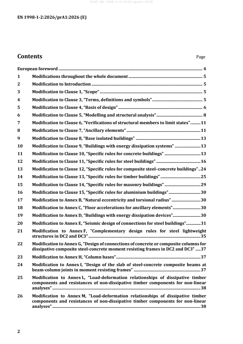
The document is organized as clause-by-clause modifications to the whole standard, starting with the foreword and then Clauses 1 to 15. It also revises Annexes B, C, D, E, F, G, H, I, L, M and O, plus the bibliography.
| Annex | What it covers |
|---|---|
| B | Natural eccentricity and torsional radius |
| C | Floor accelerations for ancillary elements |
| D | Buildings with energy dissipation devices |
| E | Seismic design of connections for steel buildings |
| F | Complementary design rules for steel lightweight structures in DC2 and DC3 |
| G | Connections of concrete or composite columns for dissipative composite steel-concrete moment resisting frames in DC2 and DC3 |
| H | Column bases in steel and composite structures |
| I | Slab of steel-concrete composite beams at beam-column joints in moment resisting frames |
| L | Load-deformation relationships of dissipative timber components and resistances of non-dissipative timber components for non-linear analyses |
| M | Load-deformation relationships of dissipative timber components and resistances of non-dissipative timber components for non-linear analyses |
| O | Material or product properties in EN 1998-1-2 |
What are the key requirements of EN 1998-1-2:2026/prA1?
EN 1998-1-2:2026/prA1 mainly tightens seismic analysis rules, clarifies how to treat damping and soil-structure interaction, and updates detailing and verification rules for concrete, steel, timber, masonry and aluminium buildings. In practice, the amendment aims to make the calculation path clearer and the material-specific checks more consistent across Eurocode 8.
Seismic modelling and global analysis
Clause 4 clarifies when a penthouse may be treated as an ancillary structure and when it is part of the building structure. If the stated conditions are met, the penthouse height is not counted in building height or elevation regularity checks, which matters because those checks affect the seismic model and the applicable rules.
Clause 4.4.5 and Clause 5.3.4 update damping treatment. When soil-structure interaction is considered, the total damping ratio ξ includes both inherent damping and soil-structure interaction damping, and the reduced spectrum is adjusted if ξ is not 5 %. This affects force levels and displacement estimates.
Clause 5.2 and 5.3 keep torsion explicit in the analysis. The standard requires minimum eccentricity with both signs at every storey, and for the force-based approach it uses separate torsional moments around the vertical axis. Annex B supports this with procedures for natural eccentricity and torsional radius.
Clause 5.3.5 aligns the displacement-based approach with a target displacement method. Local action effects are taken at the target displacement of the equivalent single degree of freedom (SDOF) model and compared with resistance from EN 1998-1-1. That matters because the engineer must check both global response and local member demand at the same deformation level.
Verification, second-order effects and special devices
Clause 6 updates verification of structural members to limit states. If second-order effects are taken from an established second-order analysis, the coefficient θ/(1+θ) must remain within the stated bound at any storey. In practice, this controls instability sensitivity.
Clause 6.2.8 distinguishes displacement-based and force-based use of behaviour factors q. The updated text points users to Clauses 10 to 15 for the material- and system-specific q values. Clause 6.2.13 also sets the amplification factor for anti-seismic devices at γ = 1.8.
Clause 6.2.10 and Clause 7.1 reinforce the checks for sliding and ancillary elements. In a displacement-based approach, sliding displacements and ancillary action effects must follow the relevant checks, which matters for non-structural and attached components that can govern safety and damage.
Ancillary elements and infills
Clause 7 updates the treatment of masonry infills and other ancillary elements. Annex C gives complementary information for floor accelerations, and Clause 7.4.2.3 provides the stiffness model for infill panels, including the strut representation used in global analysis.
Clause 7.4.2.3 also requires a non-linear analysis if the stated condition is not satisfied. In practice, this means the simpler equivalent strut model is not always enough, and the designer may need a more detailed global model.
System-specific rules
Clauses 8 and 9 cover base isolated buildings and buildings with energy dissipation systems. Clause 8 requires those buildings to satisfy the dedicated seismic clauses and EN 1998-1-1, and Clause 9 allows soil-structure interaction in energy-dissipating systems without the stated limitation in EN 1998-5. That affects whether isolation or dissipation can be combined with foundation flexibility.
Clauses 10 to 15 update the material-specific rules for concrete, steel, composite steel-concrete, timber, masonry and aluminium buildings. Table 10.1 gives default upper limit values of the behaviour factors q for several structural types, so the engineer can select the right system category before design starts.
For steel buildings, Clause 11 and Annex E cover frames, bracing systems, eccentric braced frames, buckling restrained braces, column splices and connections. For timber buildings, Clause 13 and Annex L/M focus on dissipative and non-dissipative components, dowel-type connections and nonlinear analyses. For masonry, Clause 14 updates the resistance and factor values used in design checks. For aluminium, Clause 15 links back to the steel-type seismic design framework for specific inverted pendulum structures.
What terms does EN 1998-1-2:2026/prA1 define?
- Natural eccentricity - the distance between the centre of mass and the centre of lateral stiffness of a storey.
- Total equivalent viscous damping ratio ξ - the damping ratio used in analysis, including inherent damping and the part due to soil-structure interaction.
- Soil-structure interaction (SSI) - the interaction between the structure and the supporting ground that changes the dynamic response.
- Equivalent single degree of freedom (SDOF) model - a simplified dynamic model used to derive target displacement and action effects.
- Buckling restrained brace (BRB) - a brace designed and tested to yield in a controlled way while preventing global buckling.
- Design seismic action - the seismic loading case used for design and verification.
- Penthouse - a unit on the highest floor used to host people or equipment and often not covering the whole roof deck.
Who uses EN 1998-1-2:2026/prA1?
EN 1998-1-2:2026/prA1 is used by structural engineers, seismic designers and checking engineers who design or verify buildings in seismic regions. It is also relevant to quality managers, buyers and project specifiers when they need to confirm that a project uses the correct Eurocode 8 seismic rules.
It is especially relevant for teams working on concrete, steel, composite steel-concrete, timber, masonry and aluminium buildings, plus projects with base isolation, energy dissipation systems, infills, braces, column bases and connections. Testing laboratories and manufacturers also use it where qualification tests and component properties are referenced, such as for BRBs and other energy-dissipating devices.
What changed in EN 1998-1-2:2026/prA1 from the previous edition?
EN 1998-1-2:2026/prA1 is a draft amendment to EN 1998-1-2:2026. The foreword says the main changes are corrections of symbols, terms and cross-references, better consistency with other Eurocode 8 parts, a clearer treatment of damping and soil-structure interaction, an easier formulation for infill contribution to frame stiffness, and clearer wording on how EN 1998-1-1 and EN 1998-1-2 share the displacement-based approach.
Which standards are used with EN 1998-1-2:2026/prA1?
- EN 1990-1:2023+A1:2026 - basis of structural design references used in the updated cross-references.
- EN 1998-1-1:2024 - general seismic design rules, spectra, target displacement and many common design checks.
- EN 1998-3:2025 - verification rules referenced for some seismic checks.
- EN 1998-5:2024 - foundation design and soil-structure interaction, including damping and sliding checks.
- EN 1994-1-1:2026 - composite steel-concrete design provisions used in the updated references.
- EN 1995-1-1:2025 - timber design rules used for connections, slip moduli and resistance terms.
- EN 1996-1-1:2022 - masonry design rules used for infill and masonry resistance parameters.
- EN 1993-1-8:2024 and EN 1993-1-1:2022 - steel joint and member design rules used in connection and detailing clauses.
- EN 1999-1-1:2023 - aluminium design rules referenced for aluminium building checks.
- EN 14545 and EN 14592:2022 - timber connection and fastener properties used in timber clauses.
- ISO 20987 - referenced for joints between precast concrete members.
- CEN/TS 1998-1-101 - test protocol and acceptance criteria for experimental evidence and qualification tests.
What does the EN 1998-1-2:2026/prA1 document contain?
EN 1998-1-2:2026/prA1 contains editorial and technical modification instructions, revised symbols and definitions, updated figures and formulas, and replacements of selected tables. It revises key tables such as the behaviour factors in Table 10.1, the chord-rotation partial factors in Table 11.6, the minimum ductility table in Clause 13, and the material or product properties table in Annex O.
The document also updates methods for torsion, damping, infill modelling, target displacement checks, energy dissipation systems, base isolation, BRBs, column bases, diaphragms and masonry infills. For users, the practical value is in the design workflow: choose the structural type, apply the right seismic model, verify the required member and connection resistances, and confirm any device or component through the referenced qualification and test rules.
Relations
- Amends
EN 1998-1-2:2026 - Eurocode 8 - Design of structures for earthquake resistance - Part 1-2: Buildings - Effective Date
- 17-Jun-2026
Get Certified
Connect with accredited certification bodies for this standard

DIBt (Deutsches Institut für Bautechnik)
German Institute for Building Technology.
DIN CERTCO
DIN Group product certification.

Aboma Certification B.V.
Specialized in construction, metal, and transport sectors.
Sponsored listings
Frequently Asked Questions
EN 1998-1-2:2026/prA1 is a draft published by the European Committee for Standardization (CEN). Its full title is "Eurocode 8 - Design of structures for earthquake resistance - Part 1-2: Buildings". This standard covers: EN 1998-1-2 is applicable to the design and verification of new buildings and temporary structures in seismic regions.
EN 1998-1-2 is applicable to the design and verification of new buildings and temporary structures in seismic regions.
EN 1998-1-2:2026/prA1 is classified under the following ICS (International Classification for Standards) categories: 91.010.30 - Technical aspects; 91.120.25 - Seismic and vibration protection. The ICS classification helps identify the subject area and facilitates finding related standards.
EN 1998-1-2:2026/prA1 has the following relationships with other standards: It is inter standard links to EN 1998-1-2:2026. Understanding these relationships helps ensure you are using the most current and applicable version of the standard.
EN 1998-1-2:2026/prA1 is available in PDF format for immediate download after purchase. The document can be added to your cart and obtained through the secure checkout process. Digital delivery ensures instant access to the complete standard document.
Standards Content (Sample)
SLOVENSKI STANDARD
01-november-2026
Evrokod 8 - Projektiranje potresnoodpornih konstrukcij - 1-2. del: Stavbe
Eurocode 8 - Design of structures for earthquake resistance - Part 1-2: Buildings
Eurocode 8 - Auslegung von Bauwerken gegen Erdbeben - Teil 1-2: Hochbauten
Eurocode 8 - Calcul des structures pour leur résistance au séisme - Partie 1-2 :
Bâtiments
Ta slovenski standard je istoveten z: EN 1998-1-2:2026/prA1
ICS:
91.010.30 Tehnični vidiki Technical aspects
91.120.25 Zaščita pred potresi in Seismic and vibration
vibracijami protection
2003-01.Slovenski inštitut za standardizacijo. Razmnoževanje celote ali delov tega standarda ni dovoljeno.
DRAFT
EUROPEAN STANDARD
EN 1998-1-2:2026
NORME EUROPÉENNE
EUROPÄISCHE NORM
prA1
September 2026
ICS 91.010.30; 91.120.25
English Version
Eurocode 8 - Design of structures for earthquake
resistance - Part 1-2: Buildings
Eurocode 8 - Calcul des structures pour leur résistance Eurocode 8 - Auslegung von Bauwerken gegen
au séisme - Partie 1-2 : Bâtiments Erdbeben - Teil 1-2: Hochbauten
This draft amendment is submitted to CEN members for enquiry. It has been drawn up by the Technical Committee CEN/TC 250.
This draft amendment A1, if approved, will modify the European Standard EN 1998-1-2:2026. If this draft becomes an
amendment, CEN members are bound to comply with the CEN/CENELEC Internal Regulations which stipulate the conditions for
inclusion of this amendment into the relevant national standard without any alteration.
This draft amendment was established by CEN in three official versions (English, French, German). A version in any other
language made by translation under the responsibility of a CEN member into its own language and notified to the CEN-CENELEC
Management Centre has the same status as the official versions.
CEN members are the national standards bodies of Austria, Belgium, Bulgaria, Croatia, Cyprus, Czech Republic, Denmark, Estonia,
Finland, France, Germany, Greece, Hungary, Iceland, Ireland, Italy, Latvia, Lithuania, Luxembourg, Malta, Netherlands, Norway,
Poland, Portugal, Republic of North Macedonia, Romania, Serbia, Slovakia, Slovenia, Spain, Sweden, Switzerland, Türkiye and
United Kingdom.
Recipients of this draft are invited to submit, with their comments, notification of any relevant patent rights of which they are
aware and to provide supporting documentation.
Warning : This document is not a European Standard. It is distributed for review and comments. It is subject to change without
notice and shall not be referred to as a European Standard.
EUROPEAN COMMITTEE FOR STANDARDIZATION
COMITÉ EUROPÉEN DE NORMALISATION
EUROPÄISCHES KOMITEE FÜR NORMUNG
CEN-CENELEC Management Centre: Rue de la Science 23, B-1040 Brussels
© 2026 CEN All rights of exploitation in any form and by any means reserved Ref. No. EN 1998-1-2:2026/prA1:2026 E
worldwide for CEN national Members.
Contents Page
European foreword . 4
1 Modifications throughout the whole document . 5
2 Modification to Introduction . 5
3 Modification to Clause 1, “Scope” . 5
4 Modification to Clause 3, “Terms, definitions and symbols” . 5
5 Modification to Clause 4, “Basis of design” . 6
6 Modification to Clause 5, “Modelling and structural analysis” . 8
7 Modification to Clause 6, “Verifications of structural members to limit states” . 11
8 Modification to Clause 7, “Ancillary elements” . 11
9 Modification to Clause 8, “Base isolated buildings” . 13
10 Modification to Clause 9, “Buildings with energy dissipation systems” . 13
11 Modification to Clause 10, “Specific rules for concrete buildings” . 13
12 Modification to Clause 11, “Specific rules for steel buildings” . 16
13 Modification to Clause 12, “Specific rules for composite steel–concrete buildings” . 24
14 Modification to Clause 13, “Specific rules for timber buildings” . 25
15 Modification to Clause 14, “Specific rules for masonry buildings” . 29
16 Modification to Clause 15, “Specific rules for aluminium buildings” . 30
17 Modification to Annex B, “Natural eccentricity and torsional radius” . 30
18 Modification to Annex C, “Floor accelerations for ancillary elements” . 30
19 Modification to Annex D, “Buildings with energy dissipation devices”. 30
20 Modification to Annex E, “Seismic design of connections for steel buildings” . 31
21 Modification to Annex F, “Complementary design rules for steel lightweight
structures in DC2 and DC3” . 35
22 Modification to Annex G, “Design of connections of concrete or composite columns for
dissipative composite steel-concrete moment resisting frames in DC2 and DC3” . 37
23 Modification to Annex H, “Column bases” . 37
24 Modification to Annex I, “Design of the slab of steel-concrete composite beams at
beam-column joints in moment resisting frames” . 37
25 Modification to Annex L, “Load-deformation relationships of dissipative timber
components and resistances of non-dissipative timber components for non-linear
analyses” . 38
26 Modification to Annex M, “Load-deformation relationships of dissipative timber
components and resistances of non-dissipative timber components for non-linear
analyses” . 38
27 Modification to Annex O, “Material or product properties in EN 1998-1-2” . 39
28 Modification to Bibliography. 39
European foreword
This document (EN 1998-1-2:2026/prA1:2026) has been prepared by Technical Committee CEN/TC 250
“Structural Eurocodes”, the secretariat of which is held by BSI. CEN/TC 250 is responsible for all
Structural Eurocodes and has been assigned responsibility for structural and geotechnical design matters
by CEN.
This document is currently submitted to the CEN Enquiry.
This document will amend to EN 1998-1-2:2026.
NOTE Some modifications are purely editorial corrections to improve the quality of the document and these
will not be tagged in the consolidated publication, as noted after the modification.
The following main changes to EN 1998-1-2:2026 are included in the amendment:
— corrections of symbols, terms and cross-references for consistency with the other Eurocodes;
— consistency with other Eurocode 8 parts, namely for calculation of resulting damping contributions
including soil-structure interaction;
— ease of use formulation for the contribution of infills to frame stiffness;
— clarity on the relative input of EN 1998-1-1 and of EN 1998-1-2 in the displacement-based approach;
— improved clarity through better formulation of requirements.
The first generation of EN Eurocodes was published between 2002 and 2007. This document forms part
of the second generation of the Eurocodes, which have been prepared under Mandate M/515 issued to
CEN by the European Commission and the European Free Trade Association.
The Eurocodes have been drafted to be used in conjunction with relevant execution, material, product
and test standards, and to identify requirements for execution, materials, products and testing that are
relied upon by the Eurocodes.
The Eurocodes recognize the responsibility of each Member State and have safeguarded their right to
determine values related to regulatory safety matters at national level through the use of National
Annexes.
1 Modifications throughout the whole document
Replace “EN 1990:2023” with “EN 1990-1:2023+A1:2026”
Replace “FprEN 1994-1-1:2025” with “EN 1994-1-1:2026”
Replace “FprEN 1995-1-1:2025” with “EN 1995-1-1:2025”
Replace “FprEN 1998-3:2025” with “EN 1998-3:2025”
Replace “in the seismic design situation” with “under the design seismic action”
Replace “fundamental” with “predominant”
Replace “times” with “multiplied by”, except in Table 4.1, 6.2.11(7), 11.12.1(3), 14.4.1.2(4)b)
Replace “composite steel beam” with “composite beam” and replace “composite steel beams” with
“composite beams”
2 Modification to Introduction
0.1 Replace “— EN 1990-1” with “— EN 1990”
0.2 Replace “as defined in EN 1990-1” with “as defined in EN 1990 (all parts)”
3 Modification to Clause 1, “Scope”
1.1(1) Replace “buildings and temporary” with “buildings, ancillary elements and temporary”
4 Modification to Clause 3, “Terms, definitions and symbols”
3.1.8 Replace “of-a” with “of a” and “that results” with “that result”
3.1.11 Replace “moment coupling effect” with “in-plane bending”
3.1.22 Replace “part of” with “in a masonry structure, part of”
3.2.1 Delete the repeated definition of “P ” in the Lower case Latin symbols, replace “F ” with “F ”,
tot Rd,ndb Rd,nd
replace “F ” with “F ”, and replace “e ” with “e ”
Rk,ndb Rk,nd min,y,,i min,y,i
3.2.1 Replace “reference” with “design” in the definition of E
dH,k,max
3.2.1 Replace “CLT shear-wall” with “shear wall” in the definition of F and move it to the correct
Rd,hd,i,j
alphabetical order
3.2.1 Replace the definition of F with “tensile-vertical design strength of the 2D or 3D anchoring
Rd,hd
connectors placed against overturning”
3.2.1 Replace the symbol and definition of F with “F characteristic value of the dowel-effect
v,Rk,d D,k,d
contribution per shear plane of the selected ductile failure mode providing energy dissipation, according
to EN 1995-1-1:2025, 11.2.3.2(7)”
3.2.1 Replace the symbol and definition of F with “F characteristic value of the dowel-effect
v,Rk,nd D,k,nd
contribution per shear plane of the less ductile failure mode, according to EN 1995-1-1:2025, 11.3.2”
3.2.1 Replace the symbol and definition of K with “K slip modulus of a connection at
SLS,v,mean SLS,v
serviceability limit state verifications calculated according to EN 1995-1-1:2025, 11.3.8.2”
3.2.1 Replace the symbols and definitions of L and L with “L , L width of floor at level i measured at
x,i y,i x,i y,i
right angle to direction y and x of the seismic action, respectively”
3.2.1 Add “design” before “seismic action”in the definitions of M , M , M , V , V , Ω, and γ
Ed,E Ed,E,i,j Rd,rock,i,j Ed,E,i,j Rd,a,i,j d
3.2.1 Delete “segmented” in the definitions of M , M , V , V , and k
Ed,E,i,j Rd,rock,i,j Ed,E,LLRS,i Ed,E,i,j IR
3.2.1 Add the symbol and definition “V design value of the strength of the non-dissipative
Rd,nd
component”
3.2.1 Add the symbol and definition “V characteristic value of the strength of the non-dissipative
Rk,nd
component”
* *
3.2.1 Replace symbol “ d ” with “ d ” and move it to the correct alphabetical order
t
3.2.1 Add the symbol and definition “d elastic horizontal displacement of a point in the structure obtained
e
from the linear elastic analysis”
*
3.2.1 Replace the definition of d with “equivalent yield displacement of the equivalent single degree of
y
freedom (SDOF) model”
3.2.1 Add “ or withdrawal length of a smooth nail” at the end of the definition of l
wj
3.2.1 Replace symbol “n ” with “n ”
vj v
3.2.1 Add the symbol and definition “t contact width between infill and column” and move the
con
definition of “t ” to the correct alphabetical order
ap
3.2.1 Delete the symbol and definition “t anchorage depth of a smooth nail”
w
3.2.1 Replace “partial factors on resistance at NC limit state” with “partial factor on resistance at NC limit
state, if a displacement-based approach is used” in the definition of γ
Rd,NC
3.2.1 Replace “partial factors on resistance at SD limit state” with “partial factor on resistance at SD limit
state, if a displacement-based approach is used” in the definition of γ
Rd,SD
target reliability index for the seismic design situation for
3.2.1 Add the symbol and definition “βt,LS,CC
a given limit state and consequence class”
3.2.1 Add the symbol and definition “σ total logarithmic standard deviation of the resistance
lnR
model”
3.2.1 Add the symbol and definition “ξ total equivalent viscous damping ratio of the structure, which
includes its inherent damping and the damping due to soil-structure interaction”
3.2.1 Add the symbol and definition “ξ equivalent viscous damping ratio due to soil-structure
SSI
interaction”
5 Modification to Clause 4, “Basis of design”
4.4.1(4) Replace “may include energy dissipation systems or base isolation. For buildings with energy
dissipation systems or base isolation, respectively, Clauses 8 and 9” with “may include base isolation or
energy dissipation systems. For buildings with base isolation or energy dissipation systems, respectively,
Clauses 8 or 9”
4.4.1(7) Add a NOTE after c) to read as follows: “
NOTE CEN/TS 1998-1-101 gives a loading protocol and acceptance criteria for such experimental evidence.”
4.4.1 Add a new paragraph to read as follows:
“(8) The seismic action resisting system of a penthouse may be calculated as being a part of the
building structure or, if a) to c) are satisfied, as being an ancillary structure:
a) the number of storeys of the building under the penthouse is not smaller than 4;
b) the mass of the penthouse calculated as given in 5.1.2(1) and in EN 1998-1-1:2024, 6.2.1(3), complies
with 7.1(3);
c) the resisting system of the penthouse satisfies (1) to (7).
NOTE A penthouse is a unit installed on the highest floor of a building to host people or equipment and which
often does not occupy the entire roof deck.”
4.4.2(1) Replace “analysis.” with “analysis, except if (6)b) is applied.”
4.4.2(2) Replace “caused by the most unfavourable seismic design situation.” with “under the most
unfavourable design seismic action.”
4.4.2(3) Replace “connections in timber structures should satisfy 13.2.1(7) and (8)” with “connections
between secondary timber columns and horizontal members, and between timber columns and the
foundation should have a rotational capacity consistent with the interstorey drift reached by the primary
structure at the SD limit state”
4.4.3(1) Replace the whole paragraph to read as follows:
“(1) A building should be considered torsionally flexible if the period of the first predominantly
torsional mode of vibration is greater than either of the periods of the predominant translational modes
in the two principal horizontal directions, with possible local modes and equipment modes not being
considered in this classification.
NOTE The predominant translational mode in a principal horizontal direction corresponds to the mode with
the greatest translational effective modal mass in that direction.”
4.4.3(2) Replace “stiffness C to the” with “stiffness C , to the” in the definition of r
i i i
4.4.3(2) Replace the symbols and definitions of e and e with “e , e are the coordinates in
0x,i 0y,i 0,x,i 0,y,i
direction x and y, respectively, of the centre of mass of storey i in a system of axis (x,y) with an origin at
the centre of lateral stiffness of storey i;”. Then add the following new definitions:
“e is the natural eccentricity, i.e. the distance between the centre of mass and the centre of lateral
0,i
stiffness of storey i;
F , F are the horizontal forces acting on storey i in direction x and y of the seismic action, respectively;
x,i y,i
L , L are the widths of floor at level i measured at right angle to direction y and x of the seismic action,
x,i y,i
respectively.”
Replace Figure 4.1 with the following figure: “
Figure 4.1 — Definition of axes x and y with origin at the centre of lateral stiffness C . Coordinates
i
e and e of the centre of mass G and coordinates x and y of the k-th primary resisting
0,x,i 0,y,i i k k
member with respect to C . Natural eccentricity e and width of floors L and L
i 0,i x,i y,i
”
4.4.4.2 Add a new paragraph to read as follows:
“(2) The height of penthouses satisfying 4.4.1(8)a) and b) should not be considered in the calculation
of the building height H or in the assessment of the building regularity in elevation.”
4.4.5 Replace title with “Damping”
4.4.5(2) NOTE Replace “Rules to combine explicitly the two types of damping in the analysis of structures
are given in 5.3.” with “The way to derive ξ from ξ and ξ is given in (3).”
I SSI
4.4.5 Add a new paragraph (3) to read as follows: “(3) When soil-structure interaction is considered in
the analysis, the total damping ratio of the structure, ξ, should be calculated as given in EN 1998-5:2024,
Formula (8.1), taking for the inherent damping ratio ξ the values given in (4) and (5).” and renumber the
I
following paragraphs
4.4.5(3) (new (4)) Replace “For all building heights,” with “When soil-structure interaction is considered,
for all building heights,”
4.4.5(5) (new (6)) Replace “(1) to (4) should not be applied to the analysis of buildings with energy
dissipation systems or to buildings with base isolation;” with “(1) to (5) should not be applied to the
analysis of buildings with base isolation or energy dissipation systems;”
6 Modification to Clause 5, “Modelling and structural analysis”
5.1.1(2) Replace “direction x (alternatively y)” with “direction y (alternatively x)”
5.1.3(2) Replace “4.4.1(5)” with “4.4.1(6)”
5.1.3(2) Delete “, composite” and add a NOTE to read as follows: “
NOTE For composite members, see 12.5.2”
5.2(2) Replace the whole paragraph to read as follows:
“(2) In order to comply with (1), a minimum eccentricity with both signs +e and –e
min,x,i min,x,i
(alternatively +e and –e ), measured at right angle to the considered direction y (alternatively x)
min,y,i min,y,i
of the seismic action, should be calculated at every storey i using Formula (5.2) and should be considered
as given in (3).
eL0,05 alternatively e 0,05 L (5.2)
( )
min,x,i x,i min,y,i y,i
where L and L are defined in 5.1.1(2).
x,i y,i
NOTE 1 Annex B gives procedures for the calculation of the natural eccentricity.
NOTE 2 (5.2) does not imply that a different sign of the additional eccentricity is applied at the different storeys.”
5.2(3) Replace the whole paragraph to read as follows:
“(3) When the force-based approach is used, the effects at any storey i of mass eccentricity
perpendicular to the considered direction y (alternatively x) of the seismic action may be calculated
considering independently two torsional moments M and M (alternatively M and M ) which act
y,i,1 y,i,2 x,i,1 x,i,2
around the building vertical axis and are given by Formula (5.3).
M =eF× alternatively M =e ×=F with j 1 or 2 (5.3)
( )
y,ij, x,ij, y,i x,,ij y,ij, x,i
where
are the horizontal forces acting on storey i in direction x and y of the seismic
F , F
xi, yi,
action, respectively;
e is equal to a), b)or c):
x,i,1
a) the maximum value of +e and |e |, when using planar models;
min,x,i 0,x,i
b) e – e , when using 3D models that encompass natural eccentricity if
min,x,i 0,x,i
|e | is smaller than e ;
0,x,i min,x,i
c) 0, when using 3D models that encompass natural eccentricity and if |e | is
0,x,i
greater than e ;
min,x,i
e is equal to a), b) or c):
x,i,2
a) the minimum value of -e and -|e |, when using planar models;
min,x,i 0,x,i
b) –(e + e ), when using 3D models that encompass natural eccentricity
min,x,i 0,x,i
if |e | is smaller than e ;
0,x,i min,x,i
c) 0, when using 3D models that encompass natural eccentricity if |e | is
0,x,i
greater than e ;
min,x,i
e is equal to a), b) or c):
y,i,1
a) the maximum value of +e and |e |, when using planar models;
min,y,i 0,y,i
b) e – e , when using 3D models that encompass natural eccentricity if
min,y,i 0,y,i
|e | is smaller than e ;
0,y,i min,y,i
c) 0, when using 3D models that encompass natural eccentricity if |e | is
0,y,i
greater than e ;
min,y,i
e is equal to a), b) or c):
y,i,2
a) the minimum value of -e and -|e |, when using planar models;
min,y,i 0,y,i
==
b) –(e + e ), when using 3D models that encompass natural eccentricity
min,y,i 0,y,i
if |e | is smaller than e ;
0,y,i min,y,i
c) 0, when using 3D models that encompass natural eccentricity if |e | is
0,y,i
greater than e .
min,y,i
”
5.3.2(5) Delete “ductility”
5.3.2 Add a new paragraph (8) to read as follows: “(8) In case the damping ratio ξ calculated according to
4.4.5(3) is different from 5 %, the reduced spectrum in EN 1998-1-1:2024, 6.4.1(6), should consider S (T)
e
with a damping correction factor η calculated according to EN 1998-1-1:2024, 5.2.2.2(12), Formula
(5.13).”
5.3.3(1) Replace 2 instances of “above a rigid basement” with “above the foundation or the top of a rigid
basement”
5.3.3(3) Replace “mode shape may be calculated using approximate methods of structural dynamics or
taken as given by Formula (5.6)” with “mode shape in the direction considered may be calculated using
approximate methods of structural dynamics or calculated using Formula (5.6) for T and considering
the deformed shape as given by the displacements s used in Formula (5.6) or in Formula (5.7) for the
i
mode shape”
5.3.3(4) Replace “The seismic action” with “The design seismic action” and replace “forces” with “force”
5.3.3(5) Replace “forces” with “force” and replace “top of a rigid basement” with “top of the foundation or
the top of a rigid basement”
5.3.3 Add a new paragraph (6) to read as follows: “(6) 5.3.4(2) to (4) should be satisfied.”
5.3.4(1) Replace “with EN 1998-1-1:2024, 4.4.5, 6.4.1 and 6.4.3” with “with 4.4.5 and with
EN 1998-1-1:2024, 6.4.1 and 6.4.3”
5.3.4(2) Replace the whole paragraph to read as follows: “(2) When soil-structure interaction (SSI) is
considered in the analysis, the total damping ratio of the structure, ξ, should be calculated as given in
4.4.5(3)” and renumber the following 3 Formulae as (5.9) to (5.11).
5.3.5.1(1) Add a NOTE to read as follows: “
NOTE The target displacement is given in EN 1998-1-1:2024, 6.5.4, including the amplification given by
Formula (6.30). The construction of the capacity curve is based on EN 1998-1-1:2024, 6.5.2 and 6.5.3, completed by
5.3.5.2 and 5.3.5.3 in this standard, which gives the action effects for each structural state.”
5.3.5.1 Add new paragraphs (7) to (9) to read as follows:
“(7) The definition of the capacity curve and the calculation of the seismic action effects should be
realised according to 5.3.5.2 and 5.3.5.3.
(8) The local action effects to be compared to the resistance given in EN 1998-1-1:2024, 6.7(2) or
*
6.7(3) or 6.7(4), should be those corresponding to the target displacement d of the SDOF model as given
t
by EN 1998-1-1:2024, Formulae (6.28) or (6.29), amplified by the factors c and c given in
P,k E,i
EN 1998-1-2:2026, 5.3.5.3.
(9) The local action effects calculated as given in (8) should not be greater than the resistance given
in EN 1998-1-1:2024, 6.7(2) or 6.7(3) or 6.7(4).”
5.3.5.3(2) NOTE 1 and NOTE 2 Replace 2 instances of “seismic action” with “design seismic action”
5.3.5.3(3) Replace “seismic action” with “design seismic action”
5.3.5.3(5) Replace “Formula (5.10)” with “Formula (5.9)”, add “calculated in the model of the building
when the target displacement is reached” at the end of the definition of d and d , and replace “are the
et et,k
target displacements” with “are, respectively, the target displacement”
5.3.5.3(7) Replace “Formula (5.11)” with “Formula (5.10)” and replace “L ” with “L ” in the definition of the
e e
symbol
5.3.5.3(8) Replace “Formula (5.12)” with “Formula (5.11)” and add “calculated in the model of the building
when the target displacement is reached” at the end of the definition of d
ret,i
5.3.5.3(9) Replace “25 m” with “30 m”
7 Modification to Clause 6, “Verifications of structural members to limit states”
6.1(1), 6.2.4(3), 6.2.12(1), 6.2.12(2) Replace “seismic action” with “design seismic action”
6.2.4(6) Replace the whole paragraph to read as follows:
“(6) If the second-order effects are taken into account directly by using an established method of
second-order analysis, a) and b) should be satisfied:
a) (3) should not be applied;
b) The value of θ/(1+ θ), with θ calculated with Formulae (6.2) or (6.3), should not be greater than 0,3
at any storey.”
6.2.6(6) Replace “connections” with “joints”
6.2.8(2) Replace “seismic action” with “design seismic action”, replace “are multiplied by q q γ , where”
r s d
with “are multiplied by γ , in the displacement-based approach, or by q q γ , in the force-based approach,
d r s d
where”, and replace “Values for qr and qs are given in 10 to 15 for the material and structural type used.”
with “Values of q are given in Clauses 10 to 15 for the material and structural type used. q is defined in
r s
EN 1998-1-1:2024, 6.4.1(2).”
6.2.10(2)b) Replace “displacements of the two buildings” with “displacements in that direction of the two
buildings”
6.2.10 Add a new paragraph (4) to read as follows: “(4) In a displacement-based approach, the
calculated displacements due to sliding should satisfy EN 1998-5:2024, 9.4.2.1.2(7).”
6.2.11(1) Replace “complete load path of forces from the interrupted structure above” with “complete
load path from the interrupted members above”
6.2.11(7) Replace “two times greater than” with “twice”
6.2.11(9) Replace “load path of forces” with “load path”
6.2 Add a section “6.2.13 Verification of anti-seismic devices” and a paragraph “(1) The
amplification factor in EN 1998-1-1:2024, 6.8.2.2(4), should be taken equal to γ = 1,8.”
x
6.3.2.2(1) Replace “non-structural” with “ancillary”
8 Modification to Clause 7, “Ancillary elements”
7.1(1) Replace “might” with “could”
7.1(3) Replace “most unfavourable” with “considered”, replace “all sources of overstrength” with “force
reduction” and delete “and 𝑞𝑞 is taken equal to 𝑞𝑞 calculated with Formula (C.6)”
ap,S ap,D
7.1 Add a new paragraph (4) to read as follows: “(4) The action effects in a penthouse satisfying
4.4.1(8) may be calculated as given in 7.1(2), 7.1(3) and 7.2.” and renumber the following paragraphs
7.2.1(3) Add a NOTE to read as follows: “
NOTE Annex C gives complementary information on the calculation of action effects.”
7.2.1(8) Replace 2 instances of “top of a rigid basement” with “top of the foundation or the top of a rigid
basement”
7.2.1(9) Replace “should be used as F* instead of the force at the target displacement” with “should also
y
be used”
7.3(1) Replace “it should be verified that, under the design seismic action associated to NC, the
deformation limits or other relevant limits given in EN 1998-3 are not exceeded.” with “the verifications
given in EN 1998-3:2025, 6.5.2, should be satisfied.”
7.4.2.1(6), 7.4.2.5(1), 7.5.2.1(3), 7.6.1(2) Replace “seismic action” with “design seismic action”
7.4.2.1(7) Rename NOTE to NOTE 1 and add a NOTE to read as follows: “
NOTE 2 The drift limit at DL corresponds to the peak strength of the masonry infill.”
Table 7.1 Title Replace “with masonry infills” with “with interacting masonry infills”
7.4.2.3(1) Replace the whole paragraph to read as follows:
“(1) In a linear analysis, a masonry infill panel should be characterised by its secant stiffness K ,
ap
calculated by Formula (7.9).
ωγ V
rm M ap,Rd
K = (7.9)
ap
θ h
ap,DL s
where
is the drift of an infill panel at DL as given at Table 7.1;
θ h
ap,DL s
is the material randomness factor of the infill material, defined as the ratio between
ω
rm
its mean initial shear strength f and its characteristic initial shear strength f ; ω
vm0 vk0 rm
should be taken equal to 1,3, as given in EN 1996-1-1:2022, Annex K.3.2.2(4).
”
7.4.2.3(2) Replace the whole paragraph to read as follows and add a new paragraph (3):
“(2) If the infill is modelled as a strut hinged at both ends (Figure 7.1(b)), Kap,strut, its secant stiffness to
DL, should be calculated by Formula (7.10).
KK= / cos α (7.10)
ap,strut ap
where α is the inclination of the diagonal strut over the horizontal, see Figure 7.1(b).
NOTE A single concentric diagonal strut framing into beam-column joints and with the same stiffness in tension
and compression can be used to model infills and calculate their effect on global deformation. The local effects of
additional shear in columns where compression struts are supported and in beam-column joints are considered
with 7.4.2.6 to 7.4.2.8. More sophisticated models are also available.
(3) The width w of the strut may be calculated by Formula (7.11).
s
w 0, 25 l 0, 25 l / cos α (7.11)
s s ap
where l is the length of the diagonal of the panel.”
s
and renumber the following paragraphs
==
7.4.2.3 Add a new paragraph (8) to read as follows: “(8) If Formula (7.13) is not satisfied, a non-
linear analysis should be realised.”
7.4.3.1(1) Replace “may” with “can”
7.4.3.2(4) Replace “t ” with “t ” in Formula (7.22) and in the definition of variables and replace “is the
ap con
thickness of the infill panel;” with “is the smaller of the infill thickness t and of the width b of the column
ap
in contact with the infill;”
9 Modification to Clause 8, “Base isolated buildings”
8.2.1(1) Replace the whole paragraph to read as follows: “(1) The design of base isolated buildings
should satisfy 8.2.2 to 8.2.4, 8.3, 8.4 and EN 1998-1-1:2024, 6.8.”
8.2.2(4) Replace “shocks between the substructure and the isolated structure and potential torsional
movements of the isolated structure” with “shocks between the isolated structure and non-isolated
elements of the substructure or of the surrounding ground, as well as potential torsional movements of
the isolated structure,”
8.4(1) Replace “seismic situation” with “seismic design situation”
8.4(3) Replace “may be adopted for them. Capacity design and global or local ductility conditions may be
neglected.” with “may be adopted for them regardless of the seismic action class.”
8.4(5) Replace “due to the seismic action” with “due to the design seismic action”
10 Modification to Clause 9, “Buildings with energy dissipation systems”
9.2.3(3) Replace “for the action effects of the design seismic action (i.e. associated to SD limit state)
magnified by 1,5 or for the action effects of the seismic action associated with the NC limit state not
magnified by 1,5.” with “for the design action effects at SD multiplied by a factor γx taken equal to 1,5 as
given in EN 1998-1-1:2024, 6.8.2.2(4), or for the design action effects at NC without amplification.”
9.3.1(1) Add at the end of the paragraph “Soil-structure interaction may be considered, without the
limitation of η in EN 1998-5:2024, 8.2.1(10).”
9.3.2.1(9) Replace “The seismic action” with “The design seismic action”
9.3.3.1(6) Replace “defined in Annex D, D.4.2.” with “given in 4.4.5(4) and (5).”
9.4.1(1) Replace the whole paragraph to read as follows: “(1) Structural members common to the main
structural system and to the energy dissipation system (Figure 9.1) should be considered as members of
the main structural system in the verifications.”
9.4.3(1) NOTE Replace “specified” with “design”
11 Modification to Clause 10, “Specific rules for concrete buildings”
10.1(5) Delete “10.2.2,”
10.2.3(2) Replace the whole paragraph to read as follows:
“(2) To satisfy (1)a) in the force-based approach, in each member end, the chord rotation demand as
defined in a) should not be greater than the chord rotation capacity at SD, θ , as defined in b):
SD
a) The chord rotation demand is calculated as the product of the global displacement ductility factor,
taken equal to the product of the components q and q of the behaviour factor, by the chord rotation
R D
θ at yielding of each member end, determined with the yield moment divided by the flexural stiffness
y
used in the linear analysis for the design seismic action, as given in 5.1.3(3), multiplied by one-third
of the member shear span;
b) The chord rotation capacity θ for the SD Limit State is calculated as given in EN 1998-1-1:2024,
SD
pl
Formula (6.32), in which the deformation δ takes the value θ, with θ and θ calculated as given in
y
u
EN 1998-1-1:2024, 7.2.2.1.1 and 7.2.2.1.2, and in which 𝛾𝛾 , the partial factor on resistance at SD in
Rd
terms of local deformations, is as given in Table 10.2.
NOTE The definition of the chord rotation θ is given in EN 1998-1-1:2024, 7.1. The flexural stiffness used in
the linear analysis for the design seismic action considers cracked cross-section in the way given in 5.1.3(3). The
chord rotation calculated as given in a) is generally different from θ .”
y
10.2.4(2)a) Replace “in the set of columns;” with “in that set of four columns;”
10.4.1(1)g) Replace “two large walls in the horizontal” with “two large walls, as defined in 10.9.1(1), in
the horizontal”, replace “in one of the two directions, provided that (a) and (b) are satisfied: (a)” with “in
the orthogonal direction provided that” and delete “(b) there are at least two walls meeting these
conditions in the orthogonal direction;”
10.4.1(1)h) Replace the whole list item with “h) Flat slab frames: those composed of co-planar sets of
columns connected by slabs without beams; walls perpendicular to that vertical plane of co-planar sets
of columns may alternatively be used as vertical supports to the flat slabs. Flat slab frame systems are
those in which at least 50% of the base shear is resisted by flat slab frames; flat slab frames may be dual
with other structural types, in particular moment-resisting beam-column frames and wall structures.
Dual flat slab frames are classified equivalent dual, e.g. moment resisting frame-equivalent dual
structures or wall-equivalent dual structures if, at the building base, the shear resistance of the structural
type other than the flat slab frame is greater than 50% of the total;”
10.4.2.1(2) Replace “10.1(5) and in 4.4.1(7)” with “4.4.1(7), 10.3, 10.4.4, 10.7(1) and 10.7(3) to (4)”
Table 10.1 Replace the table to read as follows: “
Table 10.1 — Default upper limit values of the behaviour factors
q q = q q q
D R S D
Structural type q
R
DC2 DC3 DC2 DC3
multi-storey, multi-bay moment
Moment resisting frame or resisting frames or moment resisting 1,3 3,9 4,9
moment resisting frame- frame-equivalent dual structures
equivalent dual structures 2,0 2,5
multi-storey, one-bay moment
without infills or with non- 1,2 3,6 4,5
resisting frames
interacting infills
one-storey moment resisting frames 1,1 3,3 4,1
Moment resisting frame or moment resisting frame-equivalent dual
1,1 1,2 1,7 2,0 3,0
structures with interacting masonry infills
wall-equivalent dual structures 1,2 3,6 4,5
Wall or
coupled walls structures 1,2 2,0 2,5 3,6 4,5
wall-equivalent dual
uncoupled walls structures 1,0 3,0 3,8
structures
large walls structures 1,0 2,0 k 3,0 k
w w
Flat slab frames and flat slab frame systems 1,1 1,2 – 2,0 –
”
10.4.2.2(2) Remove the italic in the 3 instances of “if” in Formula (10.1)
10.4.3(1)a) Replace “flat slab structures” with “flat slab frames and flat slab frame systems”
10.4.3(3) Replace “Flat slab structures” with “Flat slab frames and flat slab frame systems, as defined in
10.4.1(1)h),”
10.4.3(4) Replace “Flat slab structures” with “Flat slab frames and flat slab frame systems, as defined in
10.4.1(1)h),”
10.4.6(2) Replace “may be taken equal to 0,8.” with “may be taken equal to 0,8 if the member has yielded
or 0,67 if the member has not yielded at SD.”
Table 10.2 Replace “Rectangular” with “Rectangular web and flanges”
Table 10.3 Replace “Rectangular” with “Rectangular web and flanges”
10.5.3(1) Replace the definitions of symbols γRd and ωsh with “γRd ωsh is the product of the overstrength
partial factor, γ , and the factor accounting for hardening of the dissipative zone, ω ; it may be taken
Rd sh
equal to 1,4 for DC2 and DC3;”
10.5.4.2(5) Delete list item d)
10.6.2(1) Replace 2 instances of “in the seismic design situation” with “under the design seismic action”
10.6.2(2) Replace the definitions of symbols γ and ω with “γ ω is the product of the overstrength
Rd sh Rd sh
partial factor, γ , and the factor accounting for hardening of the dissipative zone, ω ; it may be taken
Rd sh
equal to 1,4 for DC2 and DC3;”
Formula (10.7) Replace “max” with “max”
10.6.3.2(7) Replace “d /4” with “d /4”
bL,min bL,max
10.8.2(3)a) Replace “from the analysis.” with “from the analysis and after a possible redistribution;”
10.8.2(3)b) Add at the end of list item b) “ M should not be taken greater than M’ multiplied by q;”
Edw Edw
Formula (10.11) Replace to read as follows: “
γω M q S T
( )
Rd sh Rdw,base eC
ε z + mz (10.11)”
( ) ( )
s
'
S T
M ( )
e 1
Edw,base
and add the symbols and definition “γ ω is the product of the overstrength partial factor, γ , and
Rd sh Rd
the factor accounting for hardening of the dissipative zone, ω ; it may be taken equal to 1,4 for DC2 and
sh
DC3;”
Formula (10.12) Replace to read as follows: “
0,,10 for 0 ≤ z ≤ 0 33h
w
mz 0,05 for 0,33h< z< 0,67h (10.12)”
( )
s w w
0,,25 for 0 67h ≤ z ≤ h
ww
10.8.2(5) Replace the whole paragraph to read as follows:
“(5) For DC2, alternatively to Formula (10.11), ε(z) may be taken as given by Formula (10.13).
'
ε z = min {q; 1,/4MM } (10.13)”
( )
Rdw,,base Edw base
10.8.3.1(6) Replace “The minimum compression field inclination in the web of ductile walls should be
equal to that of the diagonal” with “The compression field inclination angle with respect to the vertical in
the web of ductile walls should not be smaller than the one of the diagonal”
10.8.3.1(7) Replace “8.2.6.” with “8.2.6, as modified in EN 1998-1-1:2024, 7.2.3.” and delete the NOTE
10.8.3.2(2) Replace “10.6.3.2(2) and” with “10.6.3.2(1) to (2) and”
=
=
10.8.3.2(4) Replace “every second consecutive longitudinal” with “every alternate longitudinal”
10.8.3.2(8) Replace “vertical and horizontal bars should not exceed 300 mm for DC2 or 250 mm for DC3.”
with “vertical bars should not be greater than 300 mm for DC2 or 250 mm for DC3; the distance between
consecutive horizontal bars should satisfy the same limitations.”
10.8.3.3(10) Delete “resulting from the analysis”
10.10 Replace the title to read as follows: “Flat slab frames and flat slab frame systems”
10.10.1(1) Replace “flat slab structures” with “flat slab frames and flat slab frame systems”
10.10.1(3) Replace “columns” with “columns or walls”
10.10.1(7) Replace 6 instances of “columns” with “supporting members”
10.10.2(12) Replace several instances of “columns” and “supporting columns” with “supports”
10.10.2(14) Replace “with columns surrounded by others” with “with supports surrounded by other
supports”
10.13(2) Replace “of the seismic action” with “of the design seismic action”
10.14.2(6) NOTE Replace “Rules are given for the design of dowel joints, for the design of joints between
precast concrete structural members in ISO 20987 and for the design of joints” with “Rules for the design
of dowel joints are given for joints between precast concrete structural members in ISO 20987 and for
joints”
10.14.3.2(1) Replace “The design shear” with “The design horizontal shear”
10.14.3.3(5)b) Replace “10.11.3 should” with “10.11.2 and 10.11.3 should”
10.14.4.3(6) Replace “10.8.3.1(4) and (5)” with “10.8.3.1(5) and (6)”
10.14.5(1) Replace “by floor-to-floor joints” with “by in-floor joints”
12 Modification to Clause 11, “Specific rules for steel buildings”
11.4.1 Figure 11.2 Replace the caption text to read as follows: “Frames with concentric braces: (a) X
bracing; (b) diagonal bracing; (c) variant of diagonal bracing”
11.4.1(3) Replace “satisfy 4.4.1(7) and” with “satisfy 4.4.1(7) and EN 1998-1-1:2024, 4.1(7), and”
Formula (11.1) Replace “ν ” with “V ” and add its definition as: “V is defined in 6.2.4(1)”
tot tot tot
11.6.2(1) Add “limit state” after “Significant Damage”
Table 11.4 Replace 2 instances of “Wide flange” with “I or H sections”
at SD and 𝛾𝛾 at NC” with “partial factors 𝛾𝛾 at SD and at NC”
11.6.3(4) Replace “partial factors 𝛾𝛾Rd,SD,θ Rd,NC,θ Rd
Table 11.6 Replace the table to read as follows: “
Table 11.6 (NDP) — Partial factors for chord-rotation
Member type Section SD NC
I or H sections 1,72 2,21
Steel beam
RBS 1,72 2,21
I or H sections 1,72 2,21
Steel column
Hollow 1,61 2,00
Composite beam - 1,72 2,21
Filled rectangular 1,50 1,81
Interior composite
column
Filled circular 1,23 1,35
Filled rectangular 1,40 1,64
Exterior composite
Filled circular 1,50 1,81
column
Encased 1,72 2,21
”
11.6.4(1)e) Replace “0,010” with “0,015”
11.7.1(1) Replace the whole paragraph to read as follows: “(1) Primary members of structures should be
designed to 11.7.2 for low-dissipative structural behaviour and to 11.7.3 for non-dissipative structural
behaviour”
11.7.1(2) Add “and stiffness” after “resistance”
11.7.1(3) Replace “seismic zones should comply with 11.8.6(10) and (11).” with “seismic action classes
should comply with 11.8.6(9) to (12).”
11.7.2(1) Replace “almost” with “mostly”
11.7.2(2) Delete the whole paragraph
11.7.3(4) Replace “designed” with “verified”
11.8.5(1) Replace “is the seismic action effect” with “is the design seismic action effect” and delete the
NOTE
Table 11.9 Replace “of seismic action effect magnification factor Ω in DC2 for members” with “of design
seismic action effect magnification factor Ω in DC2 for non-dissipative members” in the title, merge the
cells in column 1 and rows 8 to 11 replacing “Fr
...