

prEN IEC 62852:2026
(Main)PV coupler for DC-application in photovoltaic systems - Safety requirements and tests
- Status
- Not Published
- Publication Date
- 23-Mar-2028
- Technical Committee
- CLC/TC 82 - Solar photovoltaic energy systems
- Drafting Committee
- IEC/TC 82 - IEC_TC_82
- Current Stage
- 4020 - Enquiry circulated - Enquiry
- Start Date
- 16-Oct-2026
- Due Date
- 28-Apr-2023
- Completion Date
- 16-Oct-2026

prEN IEC 62852:2026 is a CLC/IEC draft standard for PV couplers used in d.c. photovoltaic systems. It specifies safety requirements and tests for connectors that form a PV coupler, mainly for manufacturers, test laboratories, and system integrators working with photovoltaic wiring and equipment.
What does prEN IEC 62852:2026 specify?
prEN IEC 62852:2026 specifies the safety requirements and test methods for PV couplers in photovoltaic d.c. circuits. It defines the scope of use, the product categories, the constructional requirements, the test programme, and the annexes used for insulation coordination, protection caps, and crimp verification.
The standard applies to PV couplers for PV systems and PV arrays in class II equipment, with rated voltages up to 1 500 V d.c. and rated currents up to 125 A per contact. It also covers connectors intended to be built into, or integrated in, enclosures for photovoltaic devices. It is written for PV couplers made from connectors of the same product family and the same manufacturer, and it does not address mixed combinations of plugs and sockets from different manufacturers.
| Annex | What it covers |
|---|---|
| Annex A | Warning symbols used on PV couplers |
| Annex B | Determination and measurement of clearances and creepage distances |
| Annex C | Use of protection caps for unmated connector parts |
| Annex D | Difference between the terms connector and PV coupler |
| Annex E | Verification of correct crimping |
What are the key requirements of prEN IEC 62852:2026?
prEN IEC 62852:2026 is built around five practical themes: safe product definition, robust construction, insulation coordination, type testing, and routine production checks. Clause 5 sets the constructional rules, Clause 6 sets the test methods, and Annex B gives the detailed rules for clearances and creepage distances.
1) The product has to fit the defined PV coupler use case
Clause 1 limits the standard to PV couplers used in d.c. photovoltaic circuits and arrays, and to couplers that can be engaged and disengaged under voltage when live, but not under load. In practice, this means the manufacturer has to declare the intended electrical use and the exact product family before testing or marking.
2) Identification, marking, and documentation are part of compliance
Clause 5.2 requires identification, marking, and documentation for the coupler, including information needed to describe the product correctly. The standard also adds requirements for special information and for the identification of characteristics such as maximum rated altitude and number of operating cycles. For a buyer or integrator, this is the information used to match the coupler to the system design and installation conditions.
3) Protection against incorrect mating and electric shock is central
Clause 5 includes provision against incorrect mating, protection against electric shock, and the design of free connectors. Clause 6.3.3 verifies this with probe-based access checks and with IP code testing in the mated position. In practice, the coupler must be arranged so that hazardous live parts are not accessible in normal use and the parts cannot be wrongly paired.
4) Terminations and cable anchorage are treated as safety-critical
Clause 5 covers terminations and connection methods, cable anchorage, and mechanical strength. Clause 6.2 and Clause 6.3.15 require the test laboratory to use the manufacturer’s instructions and, where relevant, the specified tooling and conductor type. That matters because a sound connector body is not enough if the conductor connection can loosen, fail mechanically, or give unstable electrical contact.
5) Insulation coordination is checked by measurement and by test
Clause 5.18 and Annex B cover clearances and creepage distances, with consideration of overvoltage category, pollution degree, insulating material, altitude, and encapsulated parts. Clause 6.3.7 then requires verification of clearances and creepage distances according to IEC 60664-1 and Annex B. For design and qualification, this is the main insulation design rule set: the manufacturer must size the air and surface distances correctly and prove them by the prescribed method.
6) Electrical endurance, environmental stress, and mechanical durability are tested
Clause 6 includes durability of marking, temperature rise, mechanical operation, bending, dielectric strength, corrosion, mechanical strength at low temperatures, change of temperature, damp heat, insertion and withdrawal force, and effectiveness of the coupling device. The test groups in Tables 7 to 13 organize these checks into mechanical, service life, thermal, climatic, protection, and insulation-material groups. In practice, these tests show whether the coupler still works safely after repeated use and environmental exposure.
7) Contact resistance and gasket or seal materials are checked
Clause 6.3.16 requires contact resistance measurement at the mated PV coupler, with an initial value and a final value taken after the relevant test sequences. Clause 6.3.17 adds material tests for gaskets and seals, including low-temperature flexibility and aging performance. This matters because a connector can meet dimensional requirements but still fail in service if contacts degrade or sealing materials become brittle.
8) Routine testing is defined for non-rewirable free PV couplers
The routine test schedule for non-rewirable free PV couplers requires screening for accessible live parts when design or process controls cannot guarantee safety on their own. The standard describes an electrical withstand test using plane electrodes on the accessible outer surface. For production, this is the last check that limits hidden assembly defects before release.
What terms does prEN IEC 62852:2026 define?
prEN IEC 62852:2026 defines the terms that separate the PV coupler from related connector concepts.
- PV coupler - a means of connecting and disconnecting two cables, or a cable and a balance-of-system component, made from a PV pin connector and a PV socket connector from the same manufacturer.
- PV pin connector - the connector whose contact engages on its outer surface.
- PV socket connector - the connector whose contact engages on its inner surface.
- Connector under voltage (CuV) - a connector intended to be engaged or disengaged when live, but not under load.
- Connector without breaking capacity (COC) - a connector that must not be engaged or disengaged when live or under load.
- Product family - the manufacturer-defined group of mutually mateable connectors.
- Upper limiting temperature (ULT) - the maximum connector temperature at which the coupler is intended to remain operable.
- Lower limiting temperature (LLT) - the minimum temperature at which the coupler is intended to operate.
Who uses prEN IEC 62852:2026?
prEN IEC 62852:2026 is used by manufacturers of PV connectors and PV couplers, especially where products are assembled in factories or in the field. It is also used by test laboratories, certification bodies, and technical teams that qualify photovoltaic components for design approval, type testing, or production release.
In practice, the document supports connector design, marking, documentation, crimp verification, insulation coordination, environmental qualification, and routine checks during manufacture. It is relevant to PV modules, inverters, junction boxes, combiner boxes, and other photovoltaic devices that use these couplers.
What changed in prEN IEC 62852:2026 from the previous edition?
prEN IEC 62852:2026 replaces the term “connectors” with “PV coupler” in the title and in applicable text. It also adds the scope limitation that the standard applies only to PV couplers made from connectors of the same manufacturer and the same product family.
The foreword lists these other significant changes:
- new and improved definitions, with some now categorized
- factory assembled connectors and field assembled connectors added as characteristics
- added reference to IEC TS 63126 for higher ambient temperatures
- added identification items such as maximum rated altitude and number of operating cycles
- expanded documentation content
- added subclauses for special information, design requirements, and specimen assembly for field assembled connectors
- clearer treatment of correct mating and non-intermateability
- added methods for ultrasonic welding and compression terminations
- clarified cable type applicability
- added guidance on environmental protection, protection caps, and crimp verification
- expanded Annex B and added Annexes C, D, and E
- extended the damp heat test duration and added gasket and seal requirements and tests
- added pass/fail criteria to several tests and a clause for contact resistance measurement
Which standards are used with prEN IEC 62852:2026?
prEN IEC 62852:2026 relies on a set of IEC, ISO, and UL documents for test methods, ratings, and installation context.
- IEC 60050, IEC 60050-581, IEC 60050-826, IEC TS 61836 - vocabulary and PV terminology used for definitions.
- IEC 60060-1 - general rules for high-voltage test techniques and impulse testing.
- IEC 60068-1, IEC 60068-2-14, IEC 60068-2-75, IEC 60068-2-78 - atmospheric, temperature-change, impact, and damp-heat environmental tests.
- IEC 60112 - proof and comparative tracking index of insulating materials.
- IEC 60216-1, IEC 60216-5 - thermal endurance properties of insulating materials.
- IEC 60228 - conductor types used for test specimens.
- IEC 60309-1 - connector requirements and the bending test reference.
- IEC 60352-2, IEC 60352-3, IEC 60352-4, IEC 60352-5, IEC 60352-6, IEC 60352-7, IEC 60352-9 - termination technologies such as crimping, insulation displacement, press-in, insulation piercing, screwless clamping, and ultrasonic welding.
- IEC 60364-7-712 and IEC 62548-1 - photovoltaic installation and array requirements that define the application context.
- IEC 60417, IEC 60529, IEC 60664-1, IEC 61032, IEC 61140 - symbols, IP code, insulation coordination, probe tests, and protection against electric shock.
- IEC 61215-2, IEC 61730-1, IEC 62444, IEC 62930 - PV module tests, module safety, cable glands, and PV cable requirements.
- IEC 61238-1-1, IEC 61238-1-3, ISO 22479, ISO 527-1, ISO 7619-1, UL 6703, EN 50618 - compression connector tests, corrosion, material properties, alternative connector and cable references.
What does the prEN IEC 62852:2026 document contain?
prEN IEC 62852:2026 contains the full set of constructional requirements, test methods, and annex guidance needed to qualify PV couplers for photovoltaic d.c. use. Its core technical content is organized into Tables 1 to 13, which support cable anchorage, torsion, impulse voltage, creepage, specimen planning, torque, and the test groups A to G.
The document also includes Figure 1 for the bending test apparatus and Figures B.1 to B.4 for measuring clearances and creepage distances. Annex B is especially detailed, with altitude corrections, measurement rules, and worked examples for insulation coordination. Annex A provides warning symbols, Annex C guides the use of protection caps, Annex D explains the terminology shift from connector to PV coupler, and Annex E gives practical guidance for checking crimped connections.
Relations
- Effective Date
- 09-May-2023
- Effective Date
- 09-May-2023
- Effective Date
- 23-Jan-2023
Get Certified
Connect with accredited certification bodies for this standard

DNV
DNV is an independent assurance and risk management provider.

Lloyd's Register
Lloyd's Register is a global professional services organisation specialising in engineering and technology.
DNV Energy Systems
Energy and renewable energy certification.
Sponsored listings
Frequently Asked Questions
prEN IEC 62852:2026 is a draft published by CLC. Its full title is "PV coupler for DC-application in photovoltaic systems - Safety requirements and tests". This standard covers: PV coupler for DC-application in photovoltaic systems - Safety requirements and tests
PV coupler for DC-application in photovoltaic systems - Safety requirements and tests
prEN IEC 62852:2026 is classified under the following ICS (International Classification for Standards) categories: 27.160 - Solar energy engineering. The ICS classification helps identify the subject area and facilitates finding related standards.
prEN IEC 62852:2026 has the following relationships with other standards: It is inter standard links to EN 62852:2015/AC:2019-02, EN 62852:2015/A1:2020, EN 62852:2015. Understanding these relationships helps ensure you are using the most current and applicable version of the standard.
prEN IEC 62852:2026 is available in PDF format for immediate download after purchase. The document can be added to your cart and obtained through the secure checkout process. Digital delivery ensures instant access to the complete standard document.
Standards Content (Sample)
SLOVENSKI STANDARD
01-december-2026
PV-spojke za enosmerne aplikacije v fotonapetostnih sistemih - Varnostne zahteve
in preskusi
PV coupler for DC-application in photovoltaic systems - Safety requirements and tests
Steckverbinder für Gleichspannungsanwendungen in Photovoltaik-Systemen -
Sicherheitsanforderungen und Prüfungen
Connecteurs pour applications en courant continu pour systèmes photovoltaïques -
Exigences de sécurité et essais
Ta slovenski standard je istoveten z: prEN IEC 62852:2026
ICS:
27.160 Sončna energija Solar energy engineering
31.220.10 Vtiči in vtičnice, konektorji Plug-and-socket devices.
Connectors
2003-01.Slovenski inštitut za standardizacijo. Razmnoževanje celote ali delov tega standarda ni dovoljeno.
82/2690/CDV
COMMITTEE DRAFT FOR VOTE (CDV)
PROJECT NUMBER:
IEC 62852 ED2
DATE OF CIRCULATION: CLOSING DATE FOR VOTING:
2026-10-16 2027-01-08
SUPERSEDES DOCUMENTS:
82/2575/CD, 82/2603A/CC
IEC TC 82 : SOLAR PHOTOVOLTAIC ENERGY SYSTEMS
SECRETARIAT: SECRETARY:
United States of America Mr George Kelly
OF INTEREST TO THE FOLLOWING COMMITTEES: HORIZONTAL FUNCTION(S):
TC 64
ASPECTS CONCERNED:
Safety
SUBMITTED FOR CENELEC PARALLEL VOTING NOT SUBMITTED FOR CENELEC PARALLEL VOTING
Attention IEC-CENELEC parallel voting
The attention of IEC National Committees, members of
CENELEC, is drawn to the fact that this Committee Draft
for Vote (CDV) is submitted for parallel voting.
The CENELEC members are invited to vote through the
CENELEC online voting system.
This document is still under study and subject to change. It should not be used for reference purposes.
Recipients of this document are invited to submit, with their comments, notification of any relevant patent rights of
which they are aware and to provide supporting documentation.
Recipients of this document are invited to submit, with their comments, notification of any relevant “In Some
Countries” clauses to be included should this proposal proceed. Recipients are reminded that the CDV stage is
the final stage for submitting ISC clauses. (SEE AC/22/2007 OR NEW GUIDANCE DOC).
TITLE:
PV coupler for DC-application in photovoltaic systems - Safety requirements and tests
PROPOSED STABILITY DATE: 2029
NOTE FROM TC/SC OFFICERS:
This project was discussed and supported by WG2 during their meeting in 2026-04.
download this electronic file, to make a copy and to print out the content for the sole purpose of preparing National
Committee positions. You may not copy or "mirror" the file or printed version of the document, o r any part of it,
for any other purpose without permission in writing from IEC.
IEC CDV 62852 © IEC 2026
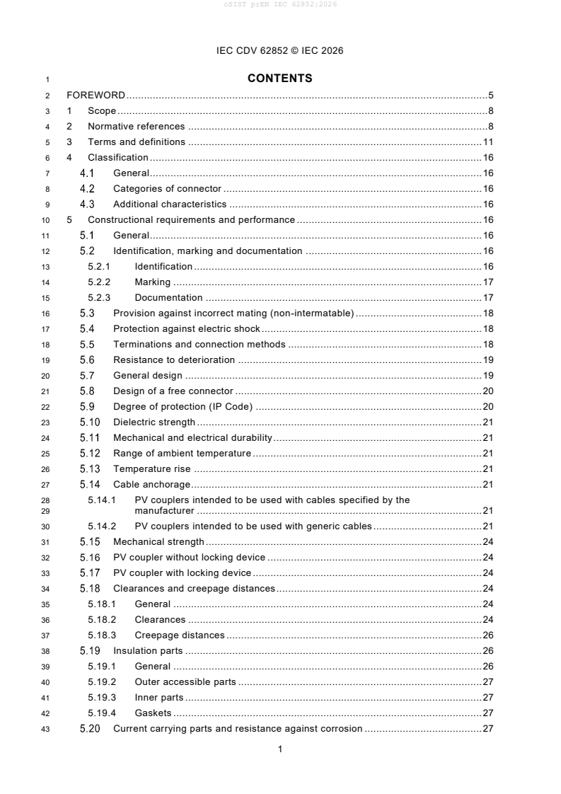
1 CONTENTS
2 FOREWORD . 5
3 1 Scope . 8
4 2 Normative references . 8
5 3 Terms and definitions . 11
6 4 Classification . 16
7 General . 16
8 Categories of connector . 16
9 Additional characteristics . 16
10 5 Constructional requirements and performance . 16
11 General . 16
12 Identification, marking and documentation . 16
13 5.2.1 Identification . 16
14 5.2.2 Marking . 17
15 5.2.3 Documentation . 17
16 Provision against incorrect mating (non-intermatable) . 18
17 Protection against electric shock . 18
18 Terminations and connection methods . 18
19 Resistance to deterioration . 19
20 General design . 19
21 Design of a free connector . 20
22 Degree of protection (IP Code) . 20
23 Dielectric strength . 21
24 Mechanical and electrical durability . 21
25 Range of ambient temperature . 21
26 Temperature rise . 21
27 Cable anchorage . 21
28 5.14.1 PV couplers intended to be used with cables specified by the
29 manufacturer . 21
30 5.14.2 PV couplers intended to be used with generic cables . 21
31 Mechanical strength . 24
32 PV coupler without locking device . 24
33 PV coupler with locking device . 24
34 Clearances and creepage distances . 24
35 5.18.1 General . 24
36 5.18.2 Clearances . 24
37 5.18.3 Creepage distances . 26
38 Insulation parts . 26
39 5.19.1 General . 26
40 5.19.2 Outer accessible parts . 27
41 5.19.3 Inner parts . 27
42 5.19.4 Gaskets . 27
43 Current carrying parts and resistance against corrosion . 27
IEC CDV 62852 © IEC 2026
44 6 Tests . 29
45 General . 29
46 Preparation of specimens . 29
47 Performance of tests . 31
48 6.3.1 General . 31
49 6.3.2 Durability of marking . 31
50 6.3.3 Protection against electric shock . 31
51 6.3.4 Temperature rise . 31
52 6.3.5 Mechanical operation . 32
53 6.3.6 Bending (flexing) test (see IEC 60309-1:2021, 24.4) . 32
54 6.3.7 Measurement of clearances and creepage distances . 33
55 6.3.8 Dielectric strength . 34
56 6.3.9 Corrosion test . 34
57 6.3.10 Mechanical strength at lower temperatures . 35
58 6.3.11 Change of temperature (IEC 60068-2-14 test Na) . 35
59 6.3.12 Damp heat test . 35
60 6.3.13 Insertion and withdrawal force . 35
61 6.3.14 Effectiveness of connector coupling device . 36
62 6.3.15 Terminations and connecting methods . 36
63 6.3.16 Measurement of contact resistance. 37
64 6.3.17 Material test for gaskets and seals. 37
65 Test schedule (routine test) for non-rewirable free PV couplers . 37
66 Test schedule . 37
67 (informative) Warning symbols used on PV couplers . 45
68 (normative) Determination and measurement of clearances and creepage
69 distances . 46
70 B.1 Influencing factors . 46
71 B.1.1 General . 46
72 B.1.2 Overvoltage category and rated impulse voltage . 46
73 B.1.3 Pollution degree . 46
74 B.1.4 Insulating material – material groups . 47
75 B.2 Clearances . 47
76 B.2.1 Evaluation of minimum clearances . 47
77 B.2.2 Verification of clearances by impulse voltage test . 48
78 B.2.2.1 Test method . 48
79 B.2.2.2 Test voltage . 48
80 B.3 Creepage distances . 49
81 B.3.1 General . 49
82 B.3.2 Creepage distances where more than one material is used, or more
83 than one pollution degree occurs . 50
84 B.4 Encapsulated parts . 50
85 B.5 Measurement of clearances and creepage distances under consideration of
86 gaps and grooves . 51
IEC CDV 62852 © IEC 2026
87 B.6 Measurement of creepage distances under consideration of different
88 pollution degrees or material groups . 54
89 B.6.1 General . 54
90 B.6.2 Different pollution degrees . 54
91 B.6.3 Different material groups . 56
92 B.7 Examples to apply Figures B.1, B.2 and B.3 at PV couplers . 57
93 . 59
94 Use of protection caps for unmated connector parts of a PV coupler . 59
95 C.1 Protection caps for temporarily application . 59
96 C.1.1 Documentation according to 5.3. 59
97 C.1.2 Degree of protection (IP-Code) according to 5.9 . 59
98 C.2 Protection caps for permanent application . 59
99 C.2.1 Documentation according to 5.3. 59
100 C.2.2 Protection against electric shock according to 5.4 . 59
101 C.2.3 Deterioration according to 5.6 . 59
102 C.2.4 Degree of protection (IP-Code) according to 5.9 . 60
103 C.2.5 Clearances and creepage distances according to 5.18 . 60
104 (informative) Difference between the terms connector and PV coupler . 61
105 D.1 General . 61
106 D.2 Connector . 61
107 D.3 PV coupler . 61
108 (informative) Verification of correct crimping . 62
109 E.1 General . 62
110 E.2 Crimping in the field . 62
111 E.3 Crimping in the factory . 62
112 E.3.1 Routine tests . 62
113 E.3.2 Sample tests . 62
114 E.4 Crimping tool . 63
115 Bibliography . 64
117 Figure 1 – Device for the bending test. 32
118 Figure A.1 – Symbol "DO NOT DISCONNECT UNDER LOAD" . 43
119 Figure A.2 – Symbol "DO NOT DISCONNECT UNDER LOAD” . 43
120 Figure B.1– Examples of methods of measuring clearances and creepage distances
121 under consideration of gaps and grooves . 52
122 Figure B.2– Examples of methods of measuring clearances and creepage distances . 53
123 Figure B.3– Examples of methods of measuring clearances and creepage distances
124 under consideration of different material groups . 54
125 Figure B.4– Examples to apply Figures B.1, B.2 and B.3 at PV-connectors . 56
127 Table 1 – Pull forces for cord anchorage . 23
128 Table 2 – Values for torsion test . 23
129 Table 3 – Rated impulse voltages and minimum clearances . 25
130 Table 4 – Creepage distances for basic insulation . 26
IEC CDV 62852 © IEC 2026
131 Table 5 – Plan of specimens required for tests . 28
132 Table 6 – Values of torque for screw-type clamping units . 29
133 Table 7 – Mechanical test group A (test group A are separate tests) . 37
134 Table 8 – Service life test group B . 38
135 Table 9 – Service life test group C . 39
136 Table 10 – Thermal test group D (mated test specimen) . 40
137 Table 11 – Climatic test group E (mated test specimen) . 41
138 Table 12 – Degree of protection, test group F . 42
139 Table 13 – Insulation material, test group G . 42
140 Table B.1 – Multiplication factors for clearances of equipment rated for operation at
141 altitudes greater than 2 000 m above sea level . 45
142 Table B.2 – Altitude correction factor for test voltage for testing (laboratory) altitudes . 46
143 Table. B.3 – Linear interpolation of withstand voltage . 47
144 Table. B.4 – Dimensions of X . 49
IEC CDV 62852 © IEC 2026
146 INTERNATIONAL ELECTROTECHNICAL COMMISSION
147 ____________
149 PV COUPLER FOR DC-APPLICATION IN PHOTOVOLTAIC SYSTEMS –
150 SAFETY REQUIREMENTS AND TESTS
152 FOREWORD
153 1) The International Electrotechnical Commission (IEC) is a worldwide organization for standardization comprising
154 all national electrotechnical committees (IEC National Committees). The object of IEC is to promote international
155 co-operation on all questions concerning standardization in the electrical and electronic fields. To this end and
156 in addition to other activities, IEC publishes International Standards, Technical Specifications, Technical Reports,
157 Publicly Available Specifications (PAS) and Guides (hereafter referred to as “IEC Publication(s)”). Their
158 preparation is entrusted to technical committees; any IEC National Committee interested in the subject dealt with
159 may participate in this preparatory work. International, governmental and non-governmental organizations liaising
160 with the IEC also participate in this preparation. IEC collaborates closely with the International Organization for
161 Standardization (ISO) in accordance with conditions determined by agreement between the two organizations.
162 2) The formal decisions or agreements of IEC on technical matters express, as nearly as possible, an international
163 consensus of opinion on the relevant subjects since each technical committee has representation from all
164 interested IEC National Committees.
165 3) IEC Publications have the form of recommendations for international use and are accepted by IEC National
166 Committees in that sense. While all reasonable efforts are made to ensure that the technical content of IEC
167 Publications is accurate, IEC cannot be held responsible for the way in which they are used or for any
168 misinterpretation by any end user.
169 4) In order to promote international uniformity, IEC National Committees undertake to apply IEC Publications
170 transparently to the maximum extent possible in their national and regional publications. Any divergence between
171 any IEC Publication and the corresponding national or regional publication shall be clearly indicated in the latter.
172 5) IEC itself does not provide any attestation of conformity. Independent certification bodies provide conformity
173 assessment services and, in some areas, access to IEC marks of conformity. IEC is not responsible for any
174 services carried out by independent certification bodies.
175 6) All users should ensure that they have the latest edition of this publication.
176 7) No liability shall attach to IEC or its directors, employees, servants or agents including individual experts and
177 members of its technical committees and IEC National Committees for any personal injury, property damage or
178 other damage of any nature whatsoever, whether direct or indirect, or for costs (including legal fees) and
179 expenses arising out of the publication, use of, or reliance upon, this IEC Publication or any other IEC
180 Publications.
181 8) Attention is drawn to the Normative references cited in this publication. Use of the referenced publications is
182 indispensable for the correct application of this publication.
183 9) Attention is drawn to the possibility that some of the elements of this IEC Publication may be the subject of patent
184 rights. IEC shall not be held responsible for identifying any or all such patent rights.
185 IEC xxxxx has been prepared by IEC technical committee 82: Solar photovoltaic energy
186 systems. It is an International Standard.
187 The text of this International Standard is based on the following documents:
Draft Report on voting
82/XX/FDIS 82/XX/RVD
189 Full information on the voting for its approval can be found in the report on voting indicated in
190 the above table.
191 The language used for the development of this International Standard is English
192 This document was drafted in accordance with ISO/IEC Directives, Part 2, and developed in
193 accordance with ISO/IEC Directives, Part 1 and ISO/IEC Directives, IEC Supplement, available
194 at www.iec.ch/members_experts/refdocs. The main document types developed by IEC are
195 described in greater detail at www.iec.ch/standardsdev/publications.
IEC CDV 62852 © IEC 2026
196 This edition included the following significant technical changes with respect to the previous
197 edition.
198 1) Replacement of the term “connectors” with “PV coupler” in title and in text where it is
199 applicable.
200 2) Addition in the scope of the statement that this standard only applies for PV couplers
201 consisting of connectors from same manufacturer and from the same product family.
202 3) New definitions added and improvement of existing definitions. Some definitions have
203 also been categorized.
204 4) “Factory assembled connectors” and “Field assembled connectors” have been added as
205 new characteristics in 4.3.
206 5) For operation in higher ambient temperatures the reference to IEC TS 63126 has been
207 added.
208 6) Beside the change in headline of section 5.2 (Identification, marking and documentation),
209 “maximum rated altitude” and “number of operating cycles” have been added in the list
210 for identification or characterization in 5.2.1 (Identification).
211 7) In 5.2.3 (Documentation) additional requirements for the content of documentation have
212 been listed.
213 8) Three subclauses for have been added for special information (5.2.4), design requirements
214 (5.7.5) and assembly of specimen (6.2.5) for field assembled connectors.
215 9) Clause 5.3 has been divided in two subclauses for a better explanation of correct mating
216 of multi-way connectors (5.3.1) and non-intermateability (5.3.2).
217 10) Clause 5.4.1 has been improved such that it is now clearer, that the connector has to
218 be mounted to the cable and has to be fully engaged to be tested.
219 11) The protection against electric shock described in 5.4.2 shall be ensured also before
220 mating both parts of the connector. Verification shall be provided by application of test
221 probe B instead of test probe 11 of IEC 61032
222 12) Supplement of two methods (ultrasonic welding and compression) for termination of the
223 conductors to the connector
224 13) In subclause 5.7.3 it is now clarified which types of cable according to IEC 62930 can
225 be applied. It is stated that cables according to EN 50618 can be used as an alternative
226 for cables Type 131 IEC 62930. Also, a hint is given that wires connected to built-in
IEC CDV 62852 © IEC 2026
227 plugs are only subject to the conditions of the respective device in which they are
228 installed.
229 14) New requirement added in 5.7.6 that manufacturer shall be able to provide suitable
230 environmental protection. Reference to new informative annex C.
231 15) The subclauses 5.18.3.2 “Pollution degree”, and 5.18.3.3 “Comparative tracking index”
232 were moved to annex B. References for explanation and evaluation of isolation
233 coordination to Annex B have been added.
234 16) The duration of weather resistance test in 5.19.2 has been extended from 500h to 1000h.
235 17) The values for RTE/RTI or TI of insulation material of outer accessible parts (5.19.2)
236 and inner parts (5.19.3) shall have a minimum value of 90°C and shall have at least the
237 same value as for ULT.
238 18) A clause (5.19.4) for requirements for gaskets and seals as well as a clause for the
239 relevant tests (6.3.17) have been added.
240 19) In a few subclauses of 6.3 of Edition 1.0 the pass/fail criteria haven’t been listed; they
241 only occur in the Tables 7 to 13. In this edition pass/fail criteria as well as the remark to
242 proceed with the tests in the relevant test groups have been added in 6.3.4
243 (Temperature rise), 6.3.5 (Mechanical operation), 6.3.9 (Corrosion test), 6.3.11 (Change
244 of temperature), and 6.3.12 (Damp heat test).
245 20) Figure 1 in 6.3.6 has been changed according to 24.4 of IEC 60309-1:2021
246 21) To avoid misunderstandings a clause (6.3.16) to describe the “Measurement of contact
247 resistance” has been added.
248 22) Annex B does now contain much more detailed description and explanation for
249 determination and measurement of clearances and creepage distances. (12 pages
250 instead of formerly 4 pages)
251 23) Informative Annex C has been added to give guidance for protection caps used for
252 unmated connector parts.
253 24) Informative Annex D has been added to explain the application of the term PV coupler
254 instead of connector.
255 25) Informative Annex E has been added with recommendations for verification of crimped
256 connections.
257 26) More detailed information about preparation of specimen for tests in test laboratories
258 added.
260 The committee has decided that the contents of this document will remain unchanged until the
261 stability date indicated on the IEC website under webstore.iec.ch in the data related to the
262 specific document. At this date, the document will be
263 • reconfirmed,
264 • withdrawn,
265 • replaced by a revised edition, or
266 • amended.
IMPORTANT – The "colour inside" logo on the cover page of this document indicates that it
contains colours which are considered to be useful for the correct understanding of its
contents. Users should therefore print this document using a colour printer.
IEC CDV 62852 © IEC 2026
271 PV COUPLER FOR DC-APPLICATION IN PHOTOVOLTAIC (PV) SYSTEMS –
272 SAFETY REQUIREMENTS AND TESTS
275 1
276 1 Scope
277 This International Standard applies to PV couplers for use in the d.c. circuits of photovoltaic systems
278 according to IEC 60364-7-712 and PV arrays according to IEC 62548-1, categorized as class II of IEC
279 61140 with rated voltages up to 1 500 V d.c. and rated currents up to 125 A per contact.
280 This standard applies to PV couplers consisting of connectors from same product family of same
281 manufacturer without breaking capacity, but which are able to be engaged and disengaged under
282 voltage (i.e. when live, Connector under voltage (CuV)).
283 Note 1 to entry: The meaning of “manufacturer” is described in 3.3.
284 This standard also applies to connectors for PV couplers which are intended to be built-in or integrated
285 in enclosures of devices for photovoltaic systems. This standard may be used as a guide for PV couplers
286 in photovoltaic systems of classes 0 and III according to IEC 61140. This document does not apply to
287 connectors for data collection, tracker controls or similar, but it may be used as a guide for those
288 connectors.
289 This standard does not cover any requirement which may be applied for tests of combinations of plugs
290 and sockets from different manufacturers.
291 Note 2 to entry: IEC 63678, Standardized plug and socket design for DC photovoltaic (PV) systems for intermatability
292 of connectors from different manufacturers is in development.
293 2 Normative references
294 The following documents, in whole or in part, are normatively referenced in this document and are
295 indispensable for its application. For dated references, only the edition cited applies. For undated
296 references, the latest edition of the referenced document (including any amendments) applies.
298 IEC 60050 (all parts): International Electrotechnical Vocabulary (available at
299 http://www.electropedia.org)
300 IEC 60060-1, High-voltage test techniques – Part 1: General definitions and test requirements
301 IEC 60068-1, Environmental testing – Part 1: General and guidance
302 IEC 60068-2-14, Environmental testing - Part 2-14: Tests - Test N: Change of temperature
303 IEC 60068-2-75, Environmental testing - Part 2-75: Tests - Test Eh: Hammer tests
304 IEC 60068-2-78, Environmental testing - Part 2-78: Tests - Test Cab: Damp heat, steady state
305 IEC 60112, Method for the determination of the proof and the comparative tracking indices of solid
306 insulating materials
307 IEC 60216-1, Electrical insulating materials – Thermal endurance properties – Part 1: Ageing
308 procedures and evaluation of test results
IEC CDV 62852 © IEC 2026
309 IEC 60216-5, Electrical insulating materials – Thermal endurance properties – Part 5: Determination of
310 relative thermal endurance index (RTE) of an insulating material
311 IEC 60228, Conductors of insulated cables
312 IEC 60309-1:2021, Plugs, fixed or portable socket-outlets and couplers for industrial purposes – Part 1:
313 General requirements
314 IEC 60352-2, Solderless connections – Part 2: Crimped connections – General requirements,
315 test methods and practical guidance
316 IEC 60352-3:2020, Solderless connections – Part 3: Accessible insulation displacement (ID)
317 connections – General requirements, test methods and practical guidance
318 IEC 60352-4:2020, Solderless connections – Part 4: Non-accessible insulation displacement
319 (ID) connections – General requirements, test methods and practical guidance
320 IEC 60352-5, Solderless connections – Part 5: Press-in connections – General requirements,
321 test methods and practical guidance
322 IEC 60352-6, Solderless connections – Part 6: Insulation piercing connections – General
323 requirements, test methods and practical guidance
324 IEC 60352-7, Solderless connections – Part 7: Spring clamp connections – General
325 requirements, test methods and practical guidance
326 IEC 60352-9, Solderless connections – Part 9: Ultrasonically welded connections – General
327 requirements, test methods and practical guidance
328 IEC 60364-7-712, Low voltage electrical installations – Part 7-712: Requirements for special installations
329 or locations – Solar photovoltaic (PV) power supply systems
330 IEC 60417, Graphical symbols for use on equipment
331 (available at http://www.graphicalsymbols.info/equipment)
332 IEC 60512-1:2018, Connectors for electronic equipment – Tests and measurements – Part 1: General
333 IEC 60512-1-1:2002, Connectors for electronic equipment - Tests and measurements - Part 1-1:
334 General examination - Test 1a: Visual examination
335 IEC 60512-2-2:2003, Connectors for electronic equipment - Tests and measurements - Part 2-2:
336 Electrical continuity and contact resistance tests - Test 2b: Contact resistance - Specified test current
337 method
338 IEC 60512-4-1:2003, Connectors for electronic equipment - Tests and measurements - Part 4-1: Voltage
339 stress test - Test 4a: Voltage proof
340 IEC 60512-5-2:2002, Connectors for electronic equipment – Tests and measurements – Part 5-2:
341 Current-carrying capacity tests; Test 5b: Current-temperature derating
342 IEC 60512-9-1:2010, Connectors for electronic equipment - Tests and measurements - Part 9-1:
343 Endurance tests - Test 9a: Mechanical operation
344 IEC 60512-11-7:2003, Connectors for electronic equipment - Tests and measurements – – Part 11-7:
345 Climatic tests – Test 11g: Flowing mixed gas corrosion test
346 IEC 60512-13-2:2006, Connectors for electronic equipment - Tests and measurements - Part 13-2:
347 Mechanical operation tests - Test 13b: Insertion and withdrawal forces
348 IEC 60512-15-6:2008, Connectors for electronic equipment - Tests and measurements - Part 15-6:
349 Connector tests (mechanical) - Test 15f: Effectiveness of connector coupling devices
350 IEC 60529:1989, Degrees of protection provided by enclosures (IP Code)
351 IEC 60664-1:2020, Insulation coordination for equipment within low-voltage supply systems –
352 Part 1: Principles, requirements and tests
IEC CDV 62852 © IEC 2026
353 IEC 60695-2-11, Fire hazard testing – Part 2-11: Glowing/hot-wire based test methods – Glow-
354 wire flammability test method for end-products
355 IEC 60695-11-10, Fire hazard testing – Part 11-10: Test flames – 50 W horizontal and vertical
356 flame test methods
357 IEC 60998-2-3, Connecting devices for low-voltage circuits for household and similar purposes
358 – Part 2-3: Particular requirements for connecting devices as separate entities with insulation -
359 piercing clamping units
360 IEC 60999-1, Connecting devices – Electrical copper conductors – Safety requirements for
361 screw-type and screwless-type clamping units – Part 1: General requirements and particular
2 2
362 requirements for clamping units for conductors from 0,2 mm up to 35 mm (included)
363 IEC 60999-2, Connecting devices – Electrical copper conductors – Safety requirements for
364 screw-type and screwless-type clamping units – Part 2: Particular requirements for clamping
2 2
365 units for conductors above 35 mm up to 300 mm (included)
366 IEC 61032, Protection of persons and equipment by enclosures – Probes for verification
367 IEC 61140, Protection against electric shock – Common aspects for installation and equipment
368 IEC 61210, Connecting devices – Flat quick-connect terminations for electrical copper
369 conductors –Safety requirements
370 IEC 61215-2:2021, Terrestrial photovoltaic (PV) modules – Design qualification and type approval – Part
371 2: Test procedures
372 IEC 61238-1-1:2018, Compression and mechanical connectors for power cables - Part 1-1: Test
373 methods and requirements for compression and mechanical connectors for power cables for rated
374 voltages up to 1 kV (Um = 1,2 kV) tested on non-insulated conductors
375 IEC 61238-1-3:2018, Compression and mechanical connectors for power cables - Part 1-1: Test
376 methods and requirements for compression and mechanical connectors for power cables for
377 rated voltages above 1 kV (Um = 1,2 kV) up to 30 kV (Um = 36 kV) tested on non-insulated
378 conductorsIEC 61730-1:2023, Photovoltaic (PV) module safety qualification – Part 1:
379 Requirements for construction
380 IEC 62368-1, Audio/video, information and communication technology equipment - Part 1:
381 Safety requirements
382 IEC 62444, Cable glands for electrical installations
383 IEC 62548-1, Photovoltaic (PV) arrays – Design requirements
384 IEC 62930, Electric cables for photovoltaic systems with a voltage rating of 1,5 kV DC
385 ISO 527-1, Plastics- Determination of tensile properties - Part 1: General principles
386 ISO 868, Plastics and ebonite – Determination of indentation hardness by means of a durometer (Shore
387 hardness)
388 ISO 4892-2, Plastics – Methods of exposure to laboratory light sources – Part 2: Xenon-arc
389 sources
390 ISO 4892-3, Plastics – Methods of exposure to laboratory light sources – Part 3: Fluorescent UV-lamps
391 ISO 22479, Corrosion of metal and alloys – Sulfur dioxide test in a humid atmosphere (fixed
392 gas method)
393 ISO 7619-1, Rubber, vulcanized or thermoplastic - Determination of indentation hardness - Part 1:
394 Durometer method (Shore hardness)
395 UL 6703, Connector for use in Photovoltaic systems
IEC CDV 62852 © IEC 2026
396 UL 746B, Polymeric Materials – Long term property evaluations
397 EN 50618, Electric cables for photovoltaic systems
399 3 Terms and definitions
400 For the purposes of this document, the terms and definitions given in IEC 60050-581, IEC
401 60050-826, IEC 60309-1, IEC 60664-1, IEC 60999-1, IEC 61140 and IEC TS 61836, as well as
402 the following apply.
403 3.1
404 PV coupler
405 a means enabling the connection and disconnection of two cables, or of a cable and a Balance-of
406 system (BOS) component, and consisting of a PV pin connector and a PV socket connector from the
407 same manufacturer
408 Note 1 to entry: A more detailed explanation is given in informative annex D
409 [SOURCE: IEC 60050-442:1998, 442-07-07, modified: Replacement of “at will of an appliance or
410 equipment to a flexible cable leading to another appliance or equipment” by “of two cables, or of a cable
411 and a Balance of system (BOS) component, and consisting of a PV pin connector and a PV socket
412 connector from the same manufacturer”]
413 3.2
414 categories of connectors
415 3.2.1
416 connector
417 component which terminates conductors for the purpose of providing connection to and disconnection
418 from a suitable mating component
419 Note 1 to entry: Connector type is a designation for all devices of a product family specified by the manufacturer.
420 Note 2 to entry: In this document the term connector means “PV connector”
421 [SOURCE: IEC 60050-581:2008, 581-06-01, Modified: Note 1 to entry and Note 2 to entry added]
422 3.2.1.1
423 PV pin connector
424 connector for PV application having a contact member intended to make electric engagement on its
425 outer surface for mating with the inner surface of another contact member
426 [SOURCE: IEC 60050-151::2001, 151-12-18 Modified: “connector for PV application having a” has
427 been added]
428 3.2.1.2
429 PV socket connector
430 connector for PV application having a contact member intended to make electric engagement on its
431 inner surface for mating with the outer surface of another contact member
432 [SOURCE: IEC 60050-151::2001, 151-12-17 Modified: “connector for PV application having a” has
433 been added, Note has been deleted]
434 3.2.2
435 multi-way connector
436 connector with more than one contact
437 Note 1 to entry: Multiple single-way connectors used in a PV-junction box are not to be regarded as a multi-way
438 connector according to this standard.
439 3.2.3
440 connector under voltage
441 CuV
442 connector specially designed to be engaged or disengaged in normal use when live but not under load
IEC CDV 62852 © IEC 2026
443 Note 1 to entry: In this standard, the term "live" is used if contacts are under an applied voltage but not necessarily
444 carrying current. The term "load" is used if a current is flowing through the contacts.
445 3.2.4
446 connector without breaking capacity
447 COC
448 connector which is not allowed to be engaged or disengaged in normal use when live or under load
449 [SOURCE: IEC 60050-581:2008, 581-27-73]
450 3.2.5
451 free connector
452 connector for attachment to the free end of a wire or cable
453 [SOURCE: IEC 60050-581:2008, 581-06-12]
454 3.2.6
455 built-in connector
456 a pre-manufactured connector that is subsequently integrated into an enclosure
457 3.2.7
458 integrated connector
459 a connector assembly that is manufactured as an integral component during enclosure fabrication
461 3.2.8
462 factory assembled connector
463 connector that is intended to be assembled and terminated to the cable under controlled conditions at
464 a manufacturer’s location.
465 3.2.9
466 field assembled connector
467 connector that is intended to be assembled and terminated to the cable in the field.
468 3.2.10
469 connector for Class II equipment
470 connector in which the protection against indirect contact is realized by double or reinforced insulation
471 Note 1 to entry: Class II according to IEC 61140
472 3.3
473 manufacturer
474 organization, situated at a stated location or locations, that carries out or controls such stages in the
475 manufacture, assessment, handling and storage of a product that enables it to accept responsibility for
476 continued compliance of the product with the relevant requirements and undertakes all obligations in
477 that connection
478 Note 1 to entry: The terms "manufacturer" and "organization" are often used interchangeably.
479 [SOURCE: IEC 60050-426: 426-27-01 with following modification: Note 2 has not been considered]
480 3.4
481 product family
482 a group of products specified by the manufacturer, consisting of connectors that are designed to be
483 mutually mateable
484 3.5
485 kind of connection
486 3.5.1
487 non-rewirable connector
488 connector so constructed that the cable cannot be separated from the connector without making it
489 permanently useless
490 [SOURCE: IEC 60050-581:581-26-33, , modified “useless”]
491 3.5.2
...