

prEN IEC 61174:2026
(Main)Maritime navigation and radiocommunication equipment and systems - Electronic chart display and information system (ECDIS) - Operational and performance requirements, methods of testing and required test results
- Status
- Not Published
- Publication Date
- 09-Mar-2028
- Technical Committee
- CLC/SR 80 - Maritime navigation and radiocommunication equipment and systems
- Current Stage
- 4020 - Enquiry circulated - Enquiry
- Start Date
- 02-Oct-2026
- Due Date
- 30-Jan-2026
- Completion Date
- 02-Oct-2026


prEN IEC 61174:2026 is a draft IEC/CENELEC standard for maritime navigation and radiocommunication equipment and systems, prepared by IEC TC 80 and circulated for parallel voting. It specifies operational and performance requirements, test methods, and required test results for Electronic chart display and information system (ECDIS) equipment used on ships. The document also covers route planning and monitoring, chart-data handling, interfaces with other bridge systems, back-up arrangements, and route exchange functions.
What does prEN IEC 61174:2026 specify?
prEN IEC 61174:2026 specifies how ECDIS shall behave in normal use and how its performance is to be tested. The document is organized into requirements clauses for display, route handling, interfaces, and software maintenance, followed by clauses for S-57 ENC charts, S-100 based data, other operational requirements, and a full test section.
The annexes add the detailed data, scenarios, symbols, interface mappings, route exchange rules, and test files that support those clauses.
| Annex | What it covers |
|---|---|
| A | System database information to be displayed during route planning and route monitoring |
| B | Navigational elements and parameters |
| C | Areas for which special conditions exist |
| D | Alerts and indications |
| E | Back-up arrangements |
| F | ECDIS in the RCDS mode of operation |
| G | Alerts and indications in the RCDS mode of operation |
| H | Scenario definitions and plots for testing |
| M | Scenarios for polar areas above 85° North |
| N | IEC 61162 interfaces |
| P | Route plan exchange format - RTZ |
| Q | Interface for reporting route transfer |
| R | Symbols |
| S | RTZ v1.2 test files |
What are the key requirements of prEN IEC 61174:2026?
prEN IEC 61174:2026 sets out the main functional and performance expectations for ECDIS, then ties them to test methods and required results. In practice, the standard asks whether the equipment shows the right information, keeps route functions consistent, exchanges data with other bridge systems, and handles failures or degraded modes in a predictable way.
Display, chart data, and navigational information
Clause 4 covers how the system database, ENDS information, and chart objects are presented. It addresses display of non-HO source data, safety contour, safety depth, dynamic water level, display scale, display categories, colours, symbols, and permanent indications.
This matters because the watchkeeper must be able to see what data is being used, at what scale, and with what level of trust. Annex A supports this by listing the system database information that must be available during route planning and monitoring, while Annex B and Annex C add the navigational parameters and special-condition areas used in the display logic.
Clause 4.6 extends the display to other navigational information such as radar information, AIS objects, own ship’s AIS information, and anchor watch. In practice, this means ECDIS is not only a chart viewer - it is also a bridge display that has to keep added layers understandable and distinguishable.
Route planning, route monitoring, and voyage recording
Clause 4.10 is one of the core parts of the standard. It covers route planning, route exchange with other equipment, route monitoring, additional mariner’s information, sensor integration, object information, LOP position fix, and voyage recording.
For operators, this means the system must support the full planning-to-execution workflow, not just display a line on the chart. It must also preserve enough information for later review and for transferring the route to other equipment or other parts of the vessel network.
Clause 4.11 covers calculations and accuracy, so route-related outputs are not only functional but also numerically controlled. Clause 4.10.9 covers voyage recording, which is important for traceability after an incident or during operational review.
Interfaces with bridge and communication equipment
Clause 4.12 and Annex N define interfaces with other equipment. The named connections include navigation and radio equipment, CAM system, VDR, BNWAS, NAVTEX or EGC for MSI, INS, route transfer within a vessel, and GMDSS radio communication equipment for received distress alerts.
In practice, this tells manufacturers and integrators what data ECDIS must exchange and which signals must be recognizable on shared physical links. Annex N also sets out the IEC 61162 sentence and PGN mappings, so installers and test labs can check interoperability instead of relying on vendor-specific assumptions.
Back-up, power, software maintenance, and quality management
Clause 4.14 covers back-up arrangements, Clause 4.15 covers power supply, Clause 4.16 covers software maintenance, Clause 4.17 covers quality management requirements, and Clause 4.18 covers user and default settings. Annex E expands the back-up requirements, including required functions, availability, reliability, warnings, and route-transfer support.
These clauses matter because ECDIS must remain usable when power is interrupted, a subsystem fails, or the primary configuration changes. They also set expectations for stored settings and controlled software behavior, which is important for repeatable operation across updates and between ships.
ENC, S-100 based data, and update handling
Clause 5 covers requirements contained in IHO publications related to S-57 ENC charts, including chart display priority, units and legend, cursor pick, date-dependent ENC objects, the presentation library, brightness and contrast, and manual or semi-automatic chart updates.
Clause 6 covers requirements contained in IHO publications related to S-100 based data. Clause 5 and Clause 6 together show that the standard is not limited to showing charts - it also governs how chart information is refreshed, checked for consistency, and presented across different data models.
Tests, alerts, and special operating cases
Clause 8 defines test methods and required test results for installation, interfaces, general display, preparation, ENC chart behavior, accuracy, visual requirements, functional requirements, and operational requirements. Annex J explains the test methods - observation, inspection of documented evidence, measurement, and analytical evaluation.
The annexes then provide the special cases needed for testing, including RCDS mode in Annex F, polar-area scenarios in Annex M, RTZ files in Annex S, and symbol definitions in Annex R. That gives laboratories and manufacturers concrete cases to verify, rather than only abstract statements.
What terms does prEN IEC 61174:2026 define?
- ECDIS - Electronic chart display and information system, the shipboard navigation display system covered by the standard.
- ENC - Electronic navigational chart, the chart data format used in the S-57-related requirements.
- RCDS - The raster chart display system mode of operation covered in Annex F.
- RTZ - The route plan exchange format, an XML route file used for route transfer between equipment.
- RTZP - The optional ZIP-based container for RTZ files and related attachments.
- VDR - Voyage data recorder, which receives specified ECDIS information through the defined interface.
- BNWAS - Bridge navigational watch alarm system, which receives operator-activity information from ECDIS.
Who uses prEN IEC 61174:2026?
prEN IEC 61174:2026 is used by shipowners, bridge officers, maritime equipment manufacturers, test laboratories, surveyors, and quality managers. Manufacturers use it to design ECDIS functions, interface behavior, route exchange, and update handling. Test labs use it to build test plans and verify display, accuracy, and operational behavior. Ship operators and buyers use it to compare systems, check interoperability with radar, VDR, BNWAS, INS, and radio equipment, and confirm that the installed ECDIS supports the ship’s navigation and route-management tasks.
What changed in prEN IEC 61174:2026 from the previous edition?
Annex U compares RTZ schema version 1.0 and version 1.2 and records the substantive changes. The main updates are:
- the schema handling for extensions is corrected and expanded, including manufacturer extension attributes and the Extensions element
- the file and schema validation rules are tightened, with version 1.2 validation made mandatory
- several data types and names are corrected for consistency, including routeChangesHistory, scheduleElement, and absFuelSave
- the maximum turn radius is reduced
- the meaning and units of some route-planning fields are aligned with the rest of the schema
- default-waypoint and optional-data handling are clarified
The document also states that RTZ v1.2 is the default export format, while v1.0 export remains selectable and both v1.0 and v1.2 import are supported.
Which standards are used with prEN IEC 61174:2026?
| Standard | What it contributes |
|---|---|
| IEC 61162-1, IEC 61162-2, IEC 61162-3, IEC 61162-450 | Sentence, PGN, and network interface rules used for ECDIS communications |
| IEC 61996-1 | VDR information header and format for transmitted ECDIS data |
| IEC 62616 | BNWAS interface context |
| IEC 63173-1, IEC 63173-2 | Route exchange and SECOM terminal communication |
| IHO S-100 family, including S-101, S-102, S-104, S-111, S-122, S-123, S-124, S-127, S-128, S-129, S-131 | S-100 based data models and product specifications used by the standard |
| ISO 9001 | Quality management requirements |
| ISO 9241-12 | Presentation and ergonomics guidance for display information |
| IMO MSC.530(106)/Rev.1, IMO MSC.191(79), IMO SN.1/Circ.243/Rev.2 | ECDIS performance, navigation-display presentation, and symbols/abbreviations guidance |
What does the prEN IEC 61174:2026 document contain?
The document contains normative annexes with route data structures, interface definitions, polar-area scenarios, RTZ route exchange rules, RTZ test files, and required symbols. It also includes informative annexes with geodetic calculation guidance, test-method guidance, safety contour and safety depth use cases, polar-water guidance, and a comparison of RTZ schema versions.
Several annexes are practical working sections rather than background text. Annex H and Annex M provide route scenarios and control points for testing, Annex N and Annex Q define interface and route-transfer details, Annex P defines the RTZ XML format and RTZP container, and Annex S supplies named RTZ v1.2 files for validation and error testing.
Relations
- Effective Date
- 20-Feb-2024
Get Certified
Connect with accredited certification bodies for this standard

DNV
DNV is an independent assurance and risk management provider.

Lloyd's Register
Lloyd's Register is a global professional services organisation specialising in engineering and technology.

FSC International
Forest Stewardship Council certification.
Sponsored listings
Frequently Asked Questions
prEN IEC 61174:2026 is a draft published by CLC. Its full title is "Maritime navigation and radiocommunication equipment and systems - Electronic chart display and information system (ECDIS) - Operational and performance requirements, methods of testing and required test results". This standard covers: Maritime navigation and radiocommunication equipment and systems - Electronic chart display and information system (ECDIS) - Operational and performance requirements, methods of testing and required test results
Maritime navigation and radiocommunication equipment and systems - Electronic chart display and information system (ECDIS) - Operational and performance requirements, methods of testing and required test results
prEN IEC 61174:2026 is classified under the following ICS (International Classification for Standards) categories: 47.020.70 - Navigation and control equipment. The ICS classification helps identify the subject area and facilitates finding related standards.
prEN IEC 61174:2026 has the following relationships with other standards: It is inter standard links to EN 61174:2015. Understanding these relationships helps ensure you are using the most current and applicable version of the standard.
prEN IEC 61174:2026 is available in PDF format for immediate download after purchase. The document can be added to your cart and obtained through the secure checkout process. Digital delivery ensures instant access to the complete standard document.
Standards Content (Sample)
SLOVENSKI STANDARD
01-november-2026
Pomorska navigacijska in radiokomunikacijska oprema in sistemi - Prikazovalnik
elektronskih kart in informacijski sistem (ECDIS) - Zahteve za delovanje in
lastnosti, preskusne metode in zahtevani rezultati preskušanja
Maritime navigation and radiocommunication equipment and systems - Electronic chart
display and information system (ECDIS) - Operational and performance requirements,
methods of testing and required test results
Navigations- und Funkkommunikationsgeräte und -systeme für die Seeschifffahrt -
Elektronisches Kartendarstellungs- und Informationssystem (ECDIS) - Betriebs- und
Leistungsanforderungen, Prüfverfahren und geforderte Prüfergebnisse
Matériels et systèmes de navigation et de radiocommunication maritimes - Système de
visualisation des cartes électroniques et d'information (ECDIS) - Exigences
opérationnelles et de fonctionnement, méthodes d'essai et résultats d'essai exigés
Ta slovenski standard je istoveten z: prEN IEC 61174:2026
ICS:
47.020.70 Navigacijska in krmilna Navigation and control
oprema equipment
2003-01.Slovenski inštitut za standardizacijo. Razmnoževanje celote ali delov tega standarda ni dovoljeno.
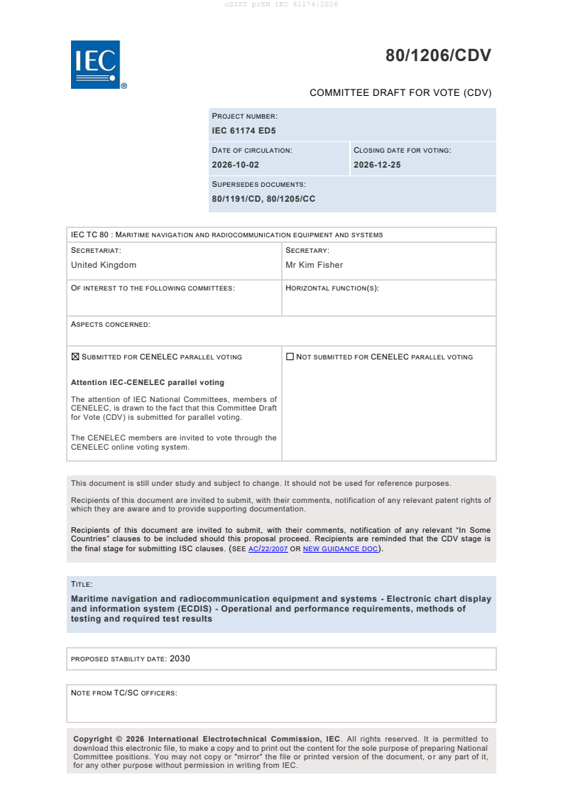
80/1206/CDV
COMMITTEE DRAFT FOR VOTE (CDV)
PROJECT NUMBER:
IEC 61174 ED5
DATE OF CIRCULATION: CLOSING DATE FOR VOTING:
2026-10-02 2026-12-25
SUPERSEDES DOCUMENTS:
80/1191/CD, 80/1205/CC
IEC TC 80 : MARITIME NAVIGATION AND RADIOCOMMUNICATION EQUIPMENT AND SYSTEMS
SECRETARIAT: SECRETARY:
United Kingdom Mr Kim Fisher
OF INTEREST TO THE FOLLOWING COMMITTEES: HORIZONTAL FUNCTION(S):
ASPECTS CONCERNED:
SUBMITTED FOR CENELEC PARALLEL VOTING NOT SUBMITTED FOR CENELEC PARALLEL VOTING
Attention IEC-CENELEC parallel voting
The attention of IEC National Committees, members of
CENELEC, is drawn to the fact that this Committee Draft
for Vote (CDV) is submitted for parallel voting.
The CENELEC members are invited to vote through the
CENELEC online voting system.
This document is still under study and subject to change. It should not be used for reference purposes.
Recipients of this document are invited to submit, with their comments, notification of any relevant patent rights of
which they are aware and to provide supporting documentation.
Recipients of this document are invited to submit, with their comments, notification of any relevant “In Some
Countries” clauses to be included should this proposal proceed. Recipients are reminded that the CDV stage is
the final stage for submitting ISC clauses. (SEE AC/22/2007 OR NEW GUIDANCE DOC).
TITLE:
Maritime navigation and radiocommunication equipment and systems - Electronic chart display
and information system (ECDIS) - Operational and performance requirements, methods of
testing and required test results
PROPOSED STABILITY DATE: 2030
NOTE FROM TC/SC OFFICERS:
download this electronic file, to make a copy and to print out the content for the sole purpose of preparing National
Committee positions. You may not copy or "mirror" the file or printed version of the document, o r any part of it,
for any other purpose without permission in writing from IEC.
IEC CDV 61174 © IEC 2026
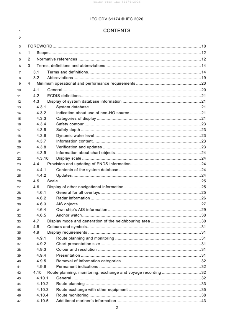
1 CONTENTS
3 FOREWORD . 10
4 1 Scope . 12
5 2 Normative references . 12
6 3 Terms, definitions and abbreviations . 14
7 3.1 Terms and definitions . 14
8 3.2 Abbreviations . 19
9 4 Minimum operational and performance requirements . 20
10 4.1 General . 20
11 4.2 ECDIS definitions . 21
12 4.3 Display of system database information . 21
13 4.3.1 System database . 21
14 4.3.2 Indication about use of non-HO source . 21
15 4.3.3 Categories of display . 21
16 4.3.4 Safety contour . 23
17 4.3.5 Safety depth . 23
18 4.3.6 Dynamic water level. 23
19 4.3.7 Information content . 23
20 4.3.8 Verification and updates . 23
21 4.3.9 Information about chart objects . 24
22 4.3.10 Display scale . 24
23 4.4 Provision and updating of ENDS information . 24
24 4.4.1 Contents of the system database . 24
25 4.4.2 Updates . 24
26 4.5 Scale . 25
27 4.6 Display of other navigational information . 25
28 4.6.1 General for all overlays . 25
29 4.6.2 Radar information . 26
30 4.6.3 AIS objects . 27
31 4.6.4 Own ship’s AIS information . 29
32 4.6.5 Anchor watch . 30
33 4.7 Display mode and generation of the neighbouring area . 30
34 4.8 Colours and symbols. 31
35 4.9 Display requirements . 31
36 4.9.1 Route planning and monitoring . 31
37 4.9.2 Chart presentation size . 31
38 4.9.3 Colour and resolution . 31
39 4.9.4 Presentation . 31
40 4.9.5 Removal of information categories . 32
41 4.9.6 Permanent indications . 32
42 4.10 Route planning, monitoring, exchange and voyage recording . 32
43 4.10.1 General . 32
44 4.10.2 Route planning . 33
45 4.10.3 Route exchange with other equipment . 35
46 4.10.4 Route monitoring . 38
47 4.10.5 Additional mariner’s information . 43
IEC CDV 61174 © IEC 2026
48 4.10.6 Sensor integration . 43
49 4.10.7 Object information . 44
50 4.10.8 LOP position fix . 44
51 4.10.9 Voyage recording . 44
52 4.11 Calculations and accuracy . 45
53 4.12 Connections with other equipment (interfaces) . 45
54 4.12.1 Connection with navigation and radio equipment . 45
55 4.12.2 Connection with CAM system . 46
56 4.12.3 Connection with VDR . 46
57 4.12.4 Connection with BNWAS . 46
58 4.12.5 Connection for system database information . 47
59 4.12.6 Connection with NAVTEX or EGC for MSI . 47
60 4.12.7 Connection for transfer of route information within a vessel . 47
61 4.12.8 Connection with INS . 48
62 4.12.9 Connection with GMDSS radio communication equipment for received
63 distress alert . 48
64 4.13 Performance tests, malfunction alerts and indications . 49
65 4.14 Back-up arrangements . 50
66 4.15 Power supply . 50
67 4.16 Software maintenance . 50
68 4.17 Quality management requirements . 50
69 4.18 User and default settings . 51
70 5 Requirements contained in IHO publications related to S-57 ENC charts . 51
71 5.1 Priority of chart display . 51
72 5.2 Display of chart information . 51
73 5.2.1 Scale and navigation purpose . 51
74 5.2.2 Units and legend. 52
75 5.2.3 Terminology . 52
76 5.3 Display functions . 52
77 5.3.1 Cursor pick . 52
78 5.3.2 Navigational information . 53
79 5.3.3 Date-dependant ENC objects . 53
80 5.4 Supplementary display functions . 53
81 5.4.1 Additional non-HO information . 53
82 5.4.2 Tidal adjustment . 54
83 5.5 Use of the presentation library . 54
84 5.5.1 Presentation library . 54
85 5.5.2 Test diagrams . 54
86 5.6 Display characteristics . 54
87 5.7 Performance requirements . 55
88 5.7.1 Redraw . 55
89 5.7.2 Resolution . 55
90 5.7.3 Symbols . 55
91 5.7.4 Number of colours . 56
92 5.7.5 Brightness and contrast . 56
93 5.8 Ergonomic requirements . 56
94 5.8.1 Mode and orientation . 56
95 5.8.2 Windows . 56
IEC CDV 61174 © IEC 2026
96 5.9 Update of chart information . 57
97 5.9.1 General . 57
98 5.9.2 Manual update . 58
99 5.9.3 Semi-automatic update . 58
100 5.9.4 Reception of updates . 58
101 5.9.5 Sequence check . 59
102 5.9.6 Consistency check . 59
103 5.9.7 Geographic applicability. 59
104 5.9.8 Summary report . 59
105 5.9.9 Review of ENC updates . 60
106 5.9.10 Modification of updates . 60
107 6 Requirements contained in IHO publications related to S-100 based data . 60
108 7 Other requirements . 60
109 7.1 Operational area . 60
110 7.2 Automatic Executable Program File Verification. . 60
111 8 Test methods and required test results . 61
112 8.1 EUT installation, technical documentation, and test requirements . 61
113 8.2 Interfaces . 61
114 8.2.1 General . 61
115 8.2.2 CAM system interface . 61
116 8.2.3 VDR interface . 62
117 8.2.4 BNWAS interface . 63
118 8.3 General requirements and presentation requirements . 63
119 8.3.1 General requirements . 63
120 8.3.2 Presentation requirements . 63
121 8.4 Preparation . 63
122 8.4.1 Power-up . 63
123 8.4.2 Initial ship parameters . 64
124 8.4.3 Required test items . 64
125 8.5 Requirements related to ENC chart . 64
126 8.5.1 General . 64
127 8.5.2 ENC . 65
128 8.5.3 Encrypted ENC . 65
129 8.6 Accuracy . 65
130 8.6.1 Presentation library . 65
131 8.7 Visual requirements . 65
132 8.7.1 Symbols . 65
133 8.7.2 Terminology, units and legend . 65
134 8.7.3 Colour table . 66
135 8.7.4 Resolution . 66
136 8.7.5 Display characteristics . 66
137 8.8 Functional requirements . 66
138 8.8.1 Test methods . 66
139 8.8.2 Standard display . 66
140 8.8.3 Display base . 67
141 8.8.4 All other information . 67
142 8.8.5 Viewing group layers and text group layers for S-57 ENC charts. 67
143 8.8.6 Context parameters for S-100 based products . 68
IEC CDV 61174 © IEC 2026
144 8.8.7 Display priorities . 68
145 8.8.8 Additional display functions . 68
146 8.8.9 Scale and navigation purpose . 68
147 8.8.10 Mode and orientation . 69
148 8.8.11 Safety contour . 69
149 8.8.12 Safety depth . 69
150 8.8.13 Object information and cursor pick . 69
151 8.8.14 Navigation related functions. 69
152 8.8.15 Sensor integration . 70
153 8.8.16 Radar and other navigational information . 70
154 8.8.17 Loading of corrupted data . 73
155 8.8.18 Automatic updates . 73
156 8.8.19 Manual updates . 74
157 8.8.20 Self-tests of major functions . 74
158 8.8.21 S-100 related standards and product specifications . 74
159 8.8.22 Operational area . 74
160 8.8.23 Automatic executable program file verification. . 75
161 8.8.24 Additional mariner’s information . 76
162 8.9 Operational requirements . 76
163 8.9.1 Ergonomic principles . 76
164 8.9.2 Route planning . 76
165 8.9.3 Route appraisal and complete route check . 79
166 8.9.4 Route plan exchange with other equipment . 80
167 8.9.5 Shore-based route exchange . 80
168 8.9.6 Route monitoring — General and safety contour . 84
169 8.9.7 Route monitoring — Hazards, areas, and current/next leg checks . 85
170 8.9.8 Route monitoring current and next leg checks. 88
171 8.9.9 Route monitoring — Alternative routes, action points, and navigation
172 tools . 88
173 8.9.10 Twelve hour log . 89
174 8.9.11 Voyage record . 90
175 8.9.12 Power supply . 90
176 8.9.13 LOP position fix . 90
177 8.10 Permanent Indications . 91
178 8.11 Software maintenance . 91
179 8.12 Quality management . 91
180 8.13 User and default settings . 92
181 8.14 AIS information and AIS target data . 92
182 8.14.1 General . 92
183 8.14.2 AIS functionality and presentation. 92
184 8.14.3 AIS target data . 92
185 8.14.4 Activation and deactivation of AIS targets . 94
186 8.14.5 AIS CPA/TCPA alarm . 94
187 8.14.6 AIS lost target warning . 95
188 8.15 AIS voyage-related data . 95
189 8.16 Anchor watch . 95
190 8.17 NAVTEX and EGC for MSI . 96
191 8.18 Interface for transfer of route information within a vessel . 97
192 8.19 Interface with INS . 97
IEC CDV 61174 © IEC 2026
193 8.20 Interface with GMDSS radio equipment for received distress alert . 98
194 Annex A (normative) System database information to be displayed during route
195 planning and route monitoring . 100
196 Annex B (normative) Navigational elements and parameters . 101
197 Annex C (normative) Areas for which special conditions exist . 102
198 Annex D (normative) Alerts and indications . 103
199 Annex E (normative) Back-up arrangements . 108
200 E.1 Overview. 108
201 E.2 Purpose . 108
202 E.3 Functional requirements . 108
203 E.3.1 Required functions and their availability . 108
204 E.3.2 Reliability and accuracy . 111
205 E.3.3 Malfunctions, warnings, alerts and indications . 112
206 E.4 Operational requirements . 112
207 E.4.1 Ergonomics . 112
208 E.4.2 Presentation of information . 112
209 E.5 Power supply . 112
210 E.6 Other requirement . 113
211 E.6.1 Connection with other systems . 113
212 E.6.2 Route transfer interface . 114
213 E.6.3 Radar as back-up system . 114
214 E.6.4 Operational area . 114
215 E.6.5 Software maintenance . 114
216 E.6.6 Quality management . 114
217 E.6.7 Default Control Settings and Saved User Control Settings . 114
218 E.6.8 External removable media . 114
219 E.7 Test methods and required test results . 114
220 E.7.1 EUT installation and technical documentation . 114
221 E.7.2 Interfaces . 115
222 E.7.3 General requirements and presentation requirements . 115
223 E.7.4 Preparation . 115
224 E.7.5 Initial data tests – Chart . 115
225 E.7.6 Accuracy . 116
226 E.7.7 Visual requirements . 116
227 E.7.8 Functional requirements . 116
228 E.7.9 Operational requirements . 118
229 Annex F (normative) ECDIS in the RCDS mode of operation . 121
230 F.1 Overview. 121
231 F.2 RCDS definitions . 121
232 F.3 Display of SRNC information . 122
233 F.3.1 SRNC . 122
234 F.3.2 Categories of display . 122
235 F.3.3 Power failure . 122
236 F.3.4 Information content . 122
237 F.3.5 Verification and updates . 122
238 F.3.6 Indication . 123
239 F.4 Provision and updating of chart information . 123
240 F.4.1 Contents of the RNC . 123
IEC CDV 61174 © IEC 2026
241 F.4.2 Updates . 123
242 F.5 Scale . 124
243 F.6 Display of other navigational information . 124
244 F.6.1 General for all overlays . 124
245 F.6.2 Radar information . 124
246 F.6.3 AIS information . 125
247 F.6.4 AIS Targets . 125
248 F.6.5 AIS CPA/TCPA alarms . 125
249 F.6.6 AIS lost target warning . 125
250 F.6.7 AIS Voyage Related Data . 125
251 F.6.8 Anchor watch . 125
252 F.7 Display mode and generation of the neighbouring area . 125
253 F.8 Colours and symbols. 126
254 F.9 Display requirements . 126
255 F.9.1 Route planning and monitoring . 126
256 F.9.2 Display characteristics . 126
257 F.9.3 Chart notes . 126
258 F.10 Route planning, monitoring, exchange and voyage recording . 127
259 F.10.1 General . 127
260 F.10.2 Route planning and exchange . 127
261 F.10.3 Route monitoring . 127
262 F.10.4 Position integration . 128
263 F.10.5 Object information . 129
264 F.10.6 LOP position fix . 129
265 F.10.7 Voyage recording . 130
266 F.11 Calculations and accuracy . 130
267 F.12 Connections with other equipment (interfaces) . 131
268 F.13 Performance tests, malfunction alerts and indications . 131
269 F.14 Back-up arrangements for RCDS mode of operation . 131
270 F.15 Power supply for RCDS mode of operation . 132
271 F.16 Requirements contained in IHO publications . 132
272 F.16.1 Structure of RNC data . 132
273 F.16.2 RNC data resolution and accuracy . 132
274 F.16.3 RNC meta-data . 133
275 F.16.4 RNC colours . 133
276 F.16.5 RNC notes, diagrams, etc . 133
277 F.16.6 Operational area . 133
278 F.16.7 External removable media . 133
279 F.17 Test methods and required test results . 134
280 F.17.1 Preparation – Required test items . 134
281 F.17.2 Initial data tests . 134
282 F.17.3 Accuracy . 135
283 F.17.4 Visual requirements . 135
284 F.17.5 Functional requirements . 136
285 F.17.6 Operational requirement . 142
286 F.18 RNC test data set . 144
287 Annex G (normative) . 145
288 Alerts and indications in the RCDS mode of operation . 145
IEC CDV 61174 © IEC 2026
289 Annex H (normative) Scenario definitions and plots . 147
290 H.1 Overview. 147
291 H.2 Scenario 1: . 148
292 H.3 Scenario 2: . 149
293 H.4 Scenario 3: . 151
294 H.5 Scenario 4: . 152
295 Annex I (informative) Guidance on geodetic calculations . 154
296 I.1 Overview. 154
297 I.2 Distance deviations between Great Circle (orthodrome) and Rhumb Line
298 (loxodrome) . 154
299 I.3 Bearing deviations at start point between Great Circle (orthodrome) and
300 Rhumb Line (loxodrome) . 155
301 Annex J (informative) Guidance for testing . 157
302 J.1 Test methods . 157
303 J.2 Observation . 157
304 J.3 Inspection of documented evidence . 157
305 J.4 Measurement . 157
306 J.5 Analytical evaluation . 158
307 Annex K (informative) Use cases for safety contour and safety depth . 159
308 Annex L (informative) Guidelines on use of electronic chart systems in polar waters . 161
309 L.1 Projection and coordinate system . 161
310 L.2 Consistency . 162
311 Annex M (normative) Scenarios for polar areas above 85° North . 163
312 Annex N (normative) IEC 61162 interfaces . 170
313 N.1 General . 170
314 N.2 VDR interface . 173
315 N.3 SECOM Terminal interface. 175
316 N.4 AIS interface and interrogation . 175
317 N.5 Route transfer interface . 175
318 Annex O (informative) Conversion between IEC 61162-1 sentences and IEC 61162-3
319 parameter group numbers . 176
320 Annex P (normative) Route plan exchange format – RTZ . 178
321 P.1 General . 178
322 P.2 RTZP Data container . 179
323 P.3 High-level description of the RTZ format . 180
324 P.4 Adaptation to third-party extensions and handling of optional dara . 180
325 P.4.1 Generic idea . 180
326 P.4.2 Unique identification of a waypoint. 180
327 P.4.3 Creation of new waypoints . 181
328 P.4.4 Change of geographic data for a waypoint . 181
329 P.4.5 Waypoint removal . 181
330 P.4.6 Waypoint modification . 181
331 P.5 Detailed RTZ format description . 181
332 P.5.1 File components . 181
333 P.5.2 Route node description . 182
334 P.5.3 RouteInfo node description . 182
335 P.5.4 Waypoints node description . 183
336 P.5.5 DefaultWaypoint node description . 183
IEC CDV 61174 © IEC 2026
337 P.5.6 Waypoint node description . 184
338 P.5.7 Storing date and time for legs . 185
339 P.5.8 Schedules node description . 186
340 P.5.9 Schedule node description . 186
341 P.5.10 Extensions node description .
...