

IEC 61169-8:2007
(Main)Radio-frequency connectors - Part 8: Sectional specification - RF coaxial connectors with inner diameter of outer conductor 6,5 mm (0,256 in) with bayonet lock - Characteristic impedance 50 Ω (type BNC)
General Information
- Abstract
IEC 61169-8:2007 It is a sectional specification (SS), provides information and rules for the preparation of detail specifications (DS) for RF coaxial connectors which may preferably be used with RF cables 60096 IEC 50-3 of IEC 60096-2. These connector patterns are for low power, quick connect/disconnect applications using a bayonet type coupling mechanism and are commonly known as type "BNC". It constitutes a technical revision. It differs from IEC 60169-8 primarily in that it contains:
- a new Clause 7: Quality assessment procedures and
- a new Clause 8: Instructions for preparation of detail specifications. Futhermore this IEC 61169-8 refers to IEC 61169-1 whereas IEC 60169-8 referred to IEC 60169-1.
- Status
- Published
- Publication Date
- 15-Feb-2007
- Technical Committee
- SC 46F - RF and microwave passive components
- Current Stage
- PPUB - Publication issued
- Start Date
- 16-Feb-2007
- Completion Date
- 30-Apr-2007
Buy Documents
IEC 61169-8:2007 - Radio-frequency connectors - Part 8: Sectional specification - RF coaxial connectors with inner diameter of outer conductor 6,5 mm (0,256 in) with bayonet lock - Characteristic impedance 50 ? (type BNC) Released:2/16/2007
IEC 61169-8:2007 - Radio-frequency connectors - Part 8: Sectional specification - RF coaxial connectors with inner diameter of outer conductor 6,5 mm (0,256 in) with bayonet lock - Characteristic impedance 50 ? (type BNC) Released:2/16/2007
Overview
IEC 61169-8:2007 is the sectional specification for RF coaxial connectors commonly known as type BNC. It covers flange and interface details for connectors with an inner diameter of outer conductor 6.5 mm (0.256 in) and characteristic impedance 50 Ω, using a bayonet lock for quick connect/disconnect, low‑power applications. The document provides rules for preparing detail specifications (DS), mandatory tests (referencing IEC 61169-1), dimensional data, gauging and test connector definitions, and recommended performance and inspection schedules.
Key Topics and Requirements
- Interface dimensions: Precise dimensional drawings and tables (mm/inch) for pin- and socket-centre BNC connectors and coupling features.
- Mechanical gauges & standard test connectors: Gauging methods and test connector geometries to verify mechanical conformity.
- Outline dimensions: Standardized connector and center-contact outline dimensions for manufacturer and design reference.
- Quality assessment procedures (Clause 7): New in this edition - guidance on ratings, characteristics, test schedules, inspection sampling and procedural requirements.
- Instructions for preparation of detail specifications (Clause 8): New guidance for creating DS documents, including identification, performance requirements, marking and test selection.
- Mandatory tests: Selection of applicable tests and references to measuring methods from IEC 61169-1 (generic RF connector requirements).
- Environmental and climatic considerations: Recommended climatic categories and references to environmental test standards (e.g., IEC 60068-1).
- Annex A: Informative information for 75 Ω variants with unspecified reflection factor.
Practical Applications
IEC 61169-8:2007 is intended for components used in:
- RF test and measurement equipment
- Broadcast and video systems (where 50 Ω BNCs are required)
- Laboratory and instrumentation cabling
- Low‑power RF interconnects requiring frequent mating/unmating
The standard facilitates consistent design, manufacturing and testing of BNC connectors to ensure mechanical compatibility and predictable electrical behaviour.
Who Uses This Standard
- Connector and cable manufacturers preparing detail specifications (DS)
- Design and test engineers specifying RF interconnects
- Quality and compliance laboratories performing acceptance and periodic tests
- Procurement and standards teams requiring conformance to international RF connector norms
Related Standards
- IEC 61169-1 - Generic specification; general requirements and measuring methods
- IEC 60096-2 (and IEC 60096 series) - Radio‑frequency cable specifications (60096 IEC 50-3)
- IEC 60068-1 - Environmental testing - general guidance
- IEC 61169 series - Other RF connector sectional specifications
Keywords: IEC 61169-8:2007, BNC connector, RF coaxial connector, 50 Ω, bayonet lock, interface dimensions, quality assessment, detail specification, IEC 61169-1, IEC 60096-2.
Relations
- Effective Date
- 05-Sep-2023
Buy Documents
IEC 61169-8:2007 - Radio-frequency connectors - Part 8: Sectional specification - RF coaxial connectors with inner diameter of outer conductor 6,5 mm (0,256 in) with bayonet lock - Characteristic impedance 50 ? (type BNC) Released:2/16/2007
IEC 61169-8:2007 - Radio-frequency connectors - Part 8: Sectional specification - RF coaxial connectors with inner diameter of outer conductor 6,5 mm (0,256 in) with bayonet lock - Characteristic impedance 50 ? (type BNC) Released:2/16/2007
Get Certified
Connect with accredited certification bodies for this standard

IMQ S.p.A. (Certification)
Italian electrical product certification.

SLG Prüf- und Zertifizierungs GmbH
German testing and certification body.

UL Solutions
Global safety science company with testing, inspection and certification.
Sponsored listings
Frequently Asked Questions
IEC 61169-8:2007 is a standard published by the International Electrotechnical Commission (IEC). Its full title is "Radio-frequency connectors - Part 8: Sectional specification - RF coaxial connectors with inner diameter of outer conductor 6,5 mm (0,256 in) with bayonet lock - Characteristic impedance 50 Ω (type BNC)". This standard covers: IEC 61169-8:2007 It is a sectional specification (SS), provides information and rules for the preparation of detail specifications (DS) for RF coaxial connectors which may preferably be used with RF cables 60096 IEC 50-3 of IEC 60096-2. These connector patterns are for low power, quick connect/disconnect applications using a bayonet type coupling mechanism and are commonly known as type "BNC". It constitutes a technical revision. It differs from IEC 60169-8 primarily in that it contains: - a new Clause 7: Quality assessment procedures and - a new Clause 8: Instructions for preparation of detail specifications. Futhermore this IEC 61169-8 refers to IEC 61169-1 whereas IEC 60169-8 referred to IEC 60169-1.
IEC 61169-8:2007 It is a sectional specification (SS), provides information and rules for the preparation of detail specifications (DS) for RF coaxial connectors which may preferably be used with RF cables 60096 IEC 50-3 of IEC 60096-2. These connector patterns are for low power, quick connect/disconnect applications using a bayonet type coupling mechanism and are commonly known as type "BNC". It constitutes a technical revision. It differs from IEC 60169-8 primarily in that it contains: - a new Clause 7: Quality assessment procedures and - a new Clause 8: Instructions for preparation of detail specifications. Futhermore this IEC 61169-8 refers to IEC 61169-1 whereas IEC 60169-8 referred to IEC 60169-1.
IEC 61169-8:2007 is classified under the following ICS (International Classification for Standards) categories: 29.120.20 - Connecting devices. The ICS classification helps identify the subject area and facilitates finding related standards.
IEC 61169-8:2007 has the following relationships with other standards: It is inter standard links to IEC 60169-8:1978/AMD2:1997. Understanding these relationships helps ensure you are using the most current and applicable version of the standard.
IEC 61169-8:2007 is available in PDF format for immediate download after purchase. The document can be added to your cart and obtained through the secure checkout process. Digital delivery ensures instant access to the complete standard document.
Standards Content (Sample)
INTERNATIONAL IEC
STANDARD 61169-8
QC 222400
First edition
2007-02
Radio-frequency connectors –
Part 8:
Sectional specification –
RF coaxial connectors with inner diameter of outer
conductor 6,5 mm (0,256 in) with bayonet lock –
Characteristic impedance 50 Ω (type BNC)
Reference number
Publication numbering
As from 1 January 1997 all IEC publications are issued with a designation in the
60000 series. For example, IEC 34-1 is now referred to as IEC 60034-1.
Consolidated editions
The IEC is now publishing consolidated versions of its publications. For example,
edition numbers 1.0, 1.1 and 1.2 refer, respectively, to the base publication, the
base publication incorporating amendment 1 and the base publication incorporating
amendments 1 and 2.
Further information on IEC publications
The technical content of IEC publications is kept under constant review by the IEC,
thus ensuring that the content reflects current technology. Information relating to
this publication, including its validity, is available in the IEC Catalogue of
publications (see below) in addition to new editions, amendments and corrigenda.
Information on the subjects under consideration and work in progress undertaken
by the technical committee which has prepared this publication, as well as the list
of publications issued, is also available from the following:
• IEC Web Site (www.iec.ch)
• Catalogue of IEC publications
The on-line catalogue on the IEC web site (www.iec.ch/searchpub) enables you to
search by a variety of criteria including text searches, technical committees
and date of publication. On-line information is also available on recently issued
publications, withdrawn and replaced publications, as well as corrigenda.
• IEC Just Published
This summary of recently issued publications (www.iec.ch/online_news/ justpub)
is also available by email. Please contact the Customer Service Centre (see
below) for further information.
• Customer Service Centre
If you have any questions regarding this publication or need further assistance,
please contact the Customer Service Centre:
Email: custserv@iec.ch
Tel: +41 22 919 02 11
Fax: +41 22 919 03 00
INTERNATIONAL IEC
STANDARD 61169-8
QC 222400
First edition
2007-02
Radio-frequency connectors –
Part 8:
Sectional specification –
RF coaxial connectors with inner diameter of outer
conductor 6,5 mm (0,256 in) with bayonet lock –
Characteristic impedance 50 Ω (type BNC)
© IEC 2007 ⎯ Copyright - all rights reserved
No part of this publication may be reproduced or utilized in any form or by any means, electronic or
mechanical, including photocopying and microfilm, without permission in writing from the publisher.
International Electrotechnical Commission, 3, rue de Varembé, PO Box 131, CH-1211 Geneva 20, Switzerland
Telephone: +41 22 919 02 11 Telefax: +41 22 919 03 00 E-mail: inmail@iec.ch Web: www.iec.ch
PRICE CODE
Commission Electrotechnique Internationale V
International Electrotechnical Commission
МеждународнаяЭлектротехническаяКомиссия
For price, see current catalogue
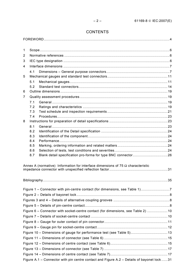
– 2 – 61169-8 © IEC:2007(E)
CONTENTS
FOREWORD.4
1 Scope.6
2 Normative references .6
3 IEC type designation .6
4 Interface dimensions .7
4.1 Dimensions – General purpose connectors.7
5 Mechanical gauges and standard test connectors.11
5.1 Mechanical gauges.11
5.2 Standard test connectors.14
6 Outline dimensions.19
7 Quality assessment procedures.19
7.1 General .19
7.2 Ratings and characteristics .19
7.3 Test schedule and inspection requirements .21
7.4 Procedures.23
8 Instructions for preparation of detail specifications .23
8.1 General .23
8.2 Identification of the Detail specification .24
8.3 Identification of the component.24
8.4 Performance.24
8.5 Marking, ordering information and related matters .24
8.6 Selection of tests, test conditions and severities.24
8.7 Blank detail specification pro-forma for type BNC connector.26
Annex A (normative) Information for interface dimensions of 75 Ω characteristic
impedance connector with unspecified reflection factor.31
Bibliography.35
Figure 1 – Connector with pin-centre contact (for dimensions, see Table 1).7
Figure 2 – Details of bayonet lock.8
Figures 3 and 4 – Details of alternative coupling grooves .8
Figure 5 – Details of pin-centre contact.8
Figure 6 – Connector with socket-centre contact (for dimensions, see Table 2) .10
Figure 7 – Details of socket-centre contact .10
Figure 8 – Gauge for outer contact of pin connector.11
Figure 9 – Gauge pin for socket-centre contact.12
Figure 10 – Dimensions of gauge for performance test (see Table 5).13
Figure 11 – Dimensions of connector (see Table 6) .15
Figure 12 – Dimensions of centre contact (see Table 6).15
Figure 13 – Dimensions of connector (see Table 7) .17
Figure 14 – Dimensions of centre contact (see Table 7).17
Figure A.1 – Connector with pin centre contact and Figure A.2 – Details of bayonet lock .31
61169-8 © IEC:2007(E) – 3 –
Figure A.3 – Details of alternative coupling grooves.31
Figure A.4 – Details of pin centre contact .31
Figure A.5 – Connector with socket centre contact.33
Figure A.6 – Position of coupling studs .33
Figure A.7 – Details of socket centre contact .33
Table 1 – Dimensions for connector with pin-centre contact.9
Table 2 – Dimensions for connector with socket-centre contact .11
Table 3 – Dimensions for gauges for outer contact of pin connector.12
Table 4 – Dimensions for gauge pin for socket-centre contact.12
Table 5 – Dimensions of gauge for performance test .14
Table 6 – Dimensions of centre contact .16
Table 7 – Dimensions for standard test connector.18
Table 8 – Preferred climatic categories (see IEC 60068-1):.19
Table 9 – Ratings and characteristics .20
Table 10 – Acceptance tests .21
Table 11 – Periodic tests .22
Table A.1 – Dimensions for pin connector .32
Table A.2 – Dimensions for socket connector .34
– 4 – 61169-8 © IEC:2007(E)
INTERNATIONAL ELECTROTECHNICAL COMMISSION
____________
RADIO-FREQUENCY CONNECTORS –
Part 8: Sectional specification – RF coaxial connectors with inner
diameter of outer conductor 6,5 mm (0,256 in) with bayonet lock –
Characteristic impedance 50 Ω (type BNC)
FOREWORD
1) The International Electrotechnical Commission (IEC) is a worldwide organization for standardization comprising
all national electrotechnical committees (IEC National Committees). The object of IEC is to promote
international co-operation on all questions concerning standardization in the electrical and electronic fields. To
this end and in addition to other activities, IEC publishes International Standards, Technical Specifications,
Technical Reports, Publicly Available Specifications (PAS) and Guides (hereafter referred to as “IEC
Publication(s)”). Their preparation is entrusted to technical committees; any IEC National Committee interested
in the subject dealt with may participate in this preparatory work. International, governmental and non-
governmental organizations liaising with the IEC also participate in this preparation. IEC collaborates closely
with the International Organization for Standardization (ISO) in accordance with conditions determined by
agreement between the two organizations.
2) The formal decisions or agreements of IEC on technical matters express, as nearly as possible, an international
consensus of opinion on the relevant subjects since each technical committee has representation from all
interested IEC National Committees.
3) IEC Publications have the form of recommendations for international use and are accepted by IEC National
Committees in that sense. While all reasonable efforts are made to ensure that the technical content of IEC
Publications is accurate, IEC cannot be held responsible for the way in which they are used or for any
misinterpretation by any end user.
4) In order to promote international uniformity, IEC National Committees undertake to apply IEC Publications
transparently to the maximum extent possible in their national and regional publications. Any divergence
between any IEC Publication and the corresponding national or regional publication shall be clearly indicated in
the latter.
5) IEC provides no marking procedure to indicate its approval and cannot be rendered responsible for any
equipment declared to be in conformity with an IEC Publication.
6) All users should ensure that they have the latest edition of this publication.
7) No liability shall attach to IEC or its directors, employees, servants or agents including individual experts and
members of its technical committees and IEC National Committees for any personal injury, property damage or
other damage of any nature whatsoever, whether direct or indirect, or for costs (including legal fees) and
expenses arising out of the publication, use of, or reliance upon, this IEC Publication or any other IEC
Publications.
8) Attention is drawn to the Normative references cited in this publication. Use of the referenced publications is
indispensable for the correct application of this publication.
9) Attention is drawn to the possibility that some of the elements of this IEC Publication may be the subject of
patent rights. IEC shall not be held responsible for identifying any or all such patent rights.
International Standard IEC 61169-8 has been prepared by subcommittee 46F: RF and
microwave passive components, of IEC technical committee 46: Cables, wires, waveguides,
RF connectors, RF and microwave passive components and accessories.
This first edition of IEC 61169-8 cancels and replaces IEC 60169-8 published in 1978 as well
as its Amendment 1 (1996) and Amendment 2 (1997). This edition constitutes a technical
revision.
This first edition of IEC 61169-8 differs from IEC 60169-8 primarily in that it contains a new
Clause 7: Quality assessment procedures and a new Clause 8: Instructions for preparation of
detail specifications. Futhermore this IEC 61169-8 refers to IEC 61169-1 whereas IEC 60169-
8 referred to IEC 60169-1.
The text of this standard is based on the following documents:
61169-8 © IEC:2007(E) – 5 –
FDIS Report on voting
46F/57/FDIS 46F/67/RVD
Full information on the voting for the approval of this standard can be found in the report on
voting indicated in the above table.
This publication has been drafted in accordance with the ISO/IEC Directives, Part 2.
A list of all parts of the IEC 61169 series, published under the general title Radio frequency
connectors, can be found on the IEC website.
The QC number that appears on the front cover of this publication is the specification number
in the IEC Quality Assessment System for Electronic Components (IECQ).
The committee has decided that the contents of this publication will remain unchanged until
the maintenance result date indicated on the IEC web site under "http://webstore.iec.ch" in
the data related to the specific publication. At this date, the publication will be
• reconfirmed,
• withdrawn,
• replaced by a revised edition, or
• amended.
A bilingual edition of this document may be issued at a later date.
– 6 – 61169-8 © IEC:2007(E)
RADIO-FREQUENCY CONNECTORS –
Part 8: Sectional specification – RF coaxial connectors with inner
diameter of outer conductor 6,5 mm (0,256 in) with bayonet lock –
Characteristic impedance 50 Ω (type BNC)
1 Scope
This part of IEC 61169, which is a sectional specification (SS), provides information and rules
for the preparation of detail specifications (DS) for RF coaxial connectors which may
preferably be used with RF cables 60096 IEC 50-3 of IEC 60096-2. These connector patterns
are for low power, quick connect/disconnect applications using a bayonet type coupling
mechanism and are commonly known as type "BNC".
It describes the interface dimensions for general purpose connectors, dimensional details for
standard test connectors together with gauging information and the mandatory tests selected
from IEC 61169-1, applicable to all DS relating to type BNC connectors.
This specification indicates the recommended performance characteristics to be considered
when writing a DS and covers test schedules and inspection requirements.
2 Normative references
The following referenced documents are indispensable for the application of this document.
For dated references, only the edition cited applies. For undated references, the latest edition
of the referenced document (including any amendments) applies.
IEC 60068-1:1988, Environmental testing – Part 1: General and guidance
Amendment 1 (1992)
IEC 60096-2, Radio-frequency cables – Part 2: Relevant cable specifications
IEC 61169-1:1992, Radio-frequency connectors – Part 1: Generic specification – General
requirements and measuring methods
3 IEC type designation
Connectors of this standard shall be designated by:
a) the reference to this standard, 61169-8 IEC;
b) a serial number (see Clause 6);
c) a letter corresponding to the climatic category (see 7.2).
Example:
61169-8-IEC-1A denotes a free pin connector belonging to climatic category 40/85/21 to be
used with an RF coaxial cable 60096 IEC 50-3-1/3/4.
NOTE The type designation used in this standard is provisional. A final type designation is under consideration.
61169-8 © IEC:2007(E) – 7 –
4 Interface dimensions
4.1 Dimensions – General purpose connectors
The original dimensions are in inches.
All undimensioned pictorial configurations are for reference purposes only.
4.1.1 Pin connector
Figure 1 – Connector with pin-centre contact (for dimensions, see Table 1)
– 8 – 61169-8 © IEC:2007(E)
IEC 113/07
Figure 2 – Details of bayonet lock
Figures 3 and 4 – Details of alternative coupling grooves
Figure 5 – Details of pin-centre contact
61169-8 © IEC:2007(E) – 9 –
Table 1 – Dimensions for connector with pin-centre contact
mm inch
Reference Note
Min. Max. Min. Max.
a 9,78 9,91 0,385 0,390 9/diam.
b – – – – 3/9/diam.
c 4,83 – 0,190 – 9/diam.
d 1,32 1,37 0,052 0,054 9/diam.
e 5,33 – 0,210 –
f 5,28 – 0,208 –
g 0,15 – 0,006 –
h 0,08 1,02 0,003 0,040
m 2,140 nom. 0,0842 nom. diam.
p 1,44 nom. 0,057 nom 10
u 5,38 – 0,212 –
v – 8,18 – 0,322 9/diam.
z 2,31 2,46 0,091 0,097 6
aa 11,76 – 0,463 – 6
ab 10,14 nom. 0,399 nom. 6
ac 1,14 – 0,045 – 6/rad.
ad 1,96 3,05 0,077 0,120
af – 0,64 – 0,025 diam.
t 4,47 4,67 0,180 0,184
w 3,15 – 0,124 –
x 0,46 0,56 0,018 0,022
y 2,31 2,46 0,091 0,097
NOTE 1 Mechanical and electrical reference plane.
NOTE 3 Slotted and flared to meet gauge test according to 5.1.1.
NOTE 6 It is permitted to use either Figure 3 or Figure 4.
NOTE 7 Sealing gasket to meet required electrical and environmental performance.
NOTE 9 Diameters shall be gauged to ensure that on mmC each feature is on or can take up a
common axis.
NOTE 10 This dimension shows the position when the bayonet sleeve is locked.
– 10 – 61169-8 © IEC:2007(E)
4.1.2 Socket connector
Figure 6 – Connector with socket-centre contact (for dimensions, see Table 2)
Figure 7 – Details of socket-centre contact
61169-8 © IEC:2007(E) – 11 –
Table 2 – Dimensions for connector with socket-centre contact
mm inch
Reference Note
Min. Max. Min. Max.
a 9,60 9,70 0,378 0,382 9/diam.
b 8,10 8,15 0.319 0,321 9/diam
c – 4,72 – 0,186 9/diam.
d - - - - 3/9/diam.
e 4,55 5,23 0,179 0,206
f - 5,28 - 0,208
g - 0,15 - 0,006
h 4,95 - 0,195 –
k – – – – 8
m 2,140 nom. 0,0842 nom. diam.
p 10,52 - 0,414 –
r – 6,50 – 0,256 4/diam.
s 8,79 9,04 0,346 0,356 diam.
t 5,18 5,28 0,204 0,208
u 8,31 8,51 0,327 0,335
v 8,31 8,46 0,327 0,333 9/diam.
ac 10,97 11,07 0,432 0,436 9
ag 1,91 2,05 0,075 0,081 diam.
NOTE 1 Mechanical and electrical reference plane.
NOTE 3 Slotted and closed to meet requirements of 5.1.2.
NOTE 4 Applies only when dielectric extends beyond reference plane.
NOTE 6 A concave depression between studs is permissible.
NOTE 8 Chamfer or radius.
NOTE 9 Diameters shall be gauged to ensure that on mmC each feature is on or can take up a
common axis.
5 Mechanical gauges and standard test connectors
5.1 Mechanical gauges
5.1.1 Connectors with pin centre contact
5.1.1.1 Gauge for outer contact of pin connector
Figure 8 – Gauge for outer contact of pin connector
– 12 – 61169-8 © IEC:2007(E)
Table 3 – Dimensions for gauges for outer contact of pin connector
Gauge B (for measurement of gauge retention
Gauge A (for sizing purposes) force for outer conductor)
Mass (weight) of gauge: 225 ± 5 g
mm inch mm inch
Reference
Min. Max. Min. Max. Min. Max. Min. Max.
a φ 9,63 9,68 0,379 0,381 9,63 9,68 0,379 0,381
b φ 8,08 8,10 0,318 0,319 8,15 8,18 0,321 0,322
u 8,41 8,46 0,331 0,333 8,36 8,41 0,329 0,331
v φ 8,31 8,36 0,327 0,329 8,41 8,46 0,331 0,333
8,79 nom. 0,346 nom. 8,79 nom. 0,346 nom.
s φ
am 4 nom. 0,157 nom. 4 nom. 0,157 nom.
Material: steel, polished; surface roughness: Ra = 0,4 μm (16 μin) maximum.
5.1.1.2 Test sequence
Gauge A shall be placed over the outer electrical contact of the connector once. This is a
sizing operation and should be carried out when the insulator is removed from the connector.
After this the gauge B shall be placed over the outer contact in a vertical position. The gauge
shall be retained.
This test can also be carried out on connectors when the insulator is not removed.
5.1.2 Connectors with socket-centre contact
5.1.2.1 Gauge pin for socket-centre contact
Figure 9 – Gauge pin for socket-centre contact
Table 4 – Dimensions for gauge pin for socket-centre contact
Gauge C (for sizing purposes) Gauge D (for measurement of gauge
retention force for inner conductor)
Mass (weight) of gauge: 57 ± 1 g
Reference mm inch mm inch
min. max. min. max. min. max. min. max.
1,372 1,377 0,0540 0,0542 1,308 1,321 0,0515 0,0520
dφ
Material: steel, polished: surface roughness: Ra = 0,4 µm (16 µin) max.
61169-8 © IEC:2007(E) – 13 –
5.1.2.2 Test sequence
A test pin gauge C shall be inserted into the centre contact a minimum distance of 3,17 mm
(0,125 in) once. This is a sizing operation and should be carried out when the insulator is
removed from the connector.
After this the gauge D shall be inserted in the vertical position. The gauge shall be retained.
This test can also be carried out on connectors when the insulator is not removed.
5.1.3 Gauge for outer contacts, coupling mechanism and mating face dimensions
A steel standard mating part shall be constructed as shown in Figure 10 for the connector and
shall have a 0,4 μm (16 μin) maximum finish. The longitudinal force required to engage or
disengage a pin connector shall not exceed 20 N.
The torque required to engage or disengage the bayonet lock of the pin connector shall not
exceed 0,25 Nm.
Figure 10 – Dimensions of gauge for performance test (see Table 5)
– 14 – 61169-8 © IEC:2007(E)
Table 5 – Dimensions of gauge for performance test
mm inch
Reference Note
Min. Max. Min. Max.
a 9,627 9,677 0,379 0,381 diam.
b 8,10 8,128 0,319 0,320 diam.
c 4,67 4,72 0,184 0,186 diam.
d 1,42 – 0,056 diam.
f 5,21 5,28 0,205 0,208
h 4,95 – 0,195 –
s 8,79 8,865 0,346 0,349 diam.
t 2,870 3,142 0,113 0,124
u 8,41 8,46 0,331 0,333
v 8,30 8,382 0,327 0,330 diam.
ac 11,024 11,074 0,434 0,436 diam.
ag 1,98 2,03 0,078 0,080
5.2 Standard test connectors
Standard test connectors are mainly used as part of the adaptor to the measuring equipment
to carry out reflection coefficient measurement according to 9.2.1 of IEC 61169-1.
61169-8 © IEC:2007(E) – 15 –
5.2.1 Standard test connector with pin contact
Figure 11 – Dimensions of connector (see Table 6)
Figure 12 – Dimensions of centre contact (see Table 6)
– 16 – 61169-8 © IEC:2007(E)
Table 6 – Dimensions of centre contact
mm Inch
Reference Note
Min. Max. Min. Max.
b 8,10 8,15 0,319 0,321 3/diam.
c 4,88 4,93 0,192 0,194 diam.
d 1,35 1,37 0,0530 0,0541 diam.
e 5,31 5,38 0,209 0,212
f 5,38 5,54 0,212 0,218
g 0,15 0,30 0,006 0,012
k 0,13 0,20 0,005 0,008 rad.
m 2,13 2,15 0,0837 0,0847 2/diam.
n 6,99 7,01 0,2752 0,2760 2/diam.
q 6,72 6,74 0,2645 0,2655 diam.
r 6,60 6,65 0,260 0,262 diam.
s 0,30 – 0,012 – plat/flat
t – 0,89 – 0,035 rad.
ad 3,66 3,98 0,144 0,157
ag 5,31 5,36 0,209 0,211
ah – 0,13 – 0,005 rad.
ak 5,16 nom. 0,203 nom.
Dimensions of bayonet lock system, see 4.1.1, Figures 2, 3 and 4
NOTE 1 Mechanical and electric reference plane. Right-angled to the axis 0,01 mm (0,0005 in).
NOTE 2 These diameters are for PTFE insulation with dielectric constant 2,02. Characteristic
impedance of transmission line determined by diameters “m” and “n” shall be 50 Ω ± 0,2 Ω.
NOTE 3 Dimensions before slotting:
six slots spaced 60 ± 1° apart,
0,36 mm - 0,41 mm (0,014 in - 0,016 in)wide,
5,84 mm - 6,10 mm (0,230 in - 0,240 in) deep,
After slotting and flaring the ID of the outer contact must be 6,718 mm to 6,744 mm
(0,2645 in to 0,2655 in) when the OD of the outer contact is inserted into a ring gauge with
an ID of 8,125 mm to 8,131 mm (0,3199 in to 0,3201 in).
NOTE 4 If concentric, radial air gap 0,05 mm (0,002 in) nom. When contact is inserted into a ring
gauge with an ID of 8,125 mm to 8,131 mm (0,3199 in to 0,3201 in).
NOTE 5 Zero air gap.
.
61169-8 © IEC:2007(E) – 17 –
5.2.2 Standard test connector with socket contact
Figure 13 – Dimensions of connector (see Table 7)
Figure 14 – Dimensions of centre contact (see Table 7)
– 18 – 61169-8 © IEC:2007(E)
Table 7 – Dimensions for standard test connector
mm inch
Reference Note
Min. Max. Min. Max.
a 9,60 9,68 0,378 0,381 diam.
b 8,10 8,15 0,319 0,321 diam.
c 4,67 4,72 0,184 0,186 diam.
d 1,356 1,361 0,0534 0,0536 3/diam.
e 5,21 5,28 0,205 0,208
f 5,08 5,23 0,200 0,206
g 0,0 0,15 0,00 0,006 8
h 5,21 – 0,205 –
...
IEC 61169-8 ®
Edition 1.0 2007-02
INTERNATIONAL
STANDARD
NORME
INTERNATIONALE
Radio-frequency connectors –
Part 8: Sectional specification – RF coaxial connectors with inner diameter of
outer conductor 6,5 mm (0,256 in) with bayonet lock – Characteristic impedance
50 Ω (type BNC)
Connecteurs pour fréquences radioélectriques –
Partie 8: Spécification intermédiaire – Connecteurs coaxiaux pour fréquences
radioélectriques avec diamètre intérieur du conducteur extérieur de 6,5 mm
(0,256 in) à verrouillage à baïonnette – Impédance caractéristique 50 Ω (type
BNC)
All rights reserved. Unless otherwise specified, no part of this publication may be reproduced or utilized in any form
or by any means, electronic or mechanical, including photocopying and microfilm, without permission in writing from
either IEC or IEC's member National Committee in the country of the requester. If you have any questions about IEC
copyright or have an enquiry about obtaining additional rights to this publication, please contact the address below or
your local IEC member National Committee for further information.
Droits de reproduction réservés. Sauf indication contraire, aucune partie de cette publication ne peut être reproduite
ni utilisée sous quelque forme que ce soit et par aucun procédé, électronique ou mécanique, y compris la photocopie
et les microfilms, sans l'accord écrit de l'IEC ou du Comité national de l'IEC du pays du demandeur. Si vous avez des
questions sur le copyright de l'IEC ou si vous désirez obtenir des droits supplémentaires sur cette publication, utilisez
les coordonnées ci-après ou contactez le Comité national de l'IEC de votre pays de résidence.
IEC Central Office Tel.: +41 22 919 02 11
3, rue de Varembé Fax: +41 22 919 03 00
CH-1211 Geneva 20 info@iec.ch
Switzerland www.iec.ch
About the IEC
The International Electrotechnical Commission (IEC) is the leading global organization that prepares and publishes
International Standards for all electrical, electronic and related technologies.
About IEC publications
The technical content of IEC publications is kept under constant review by the IEC. Please make sure that you have the
latest edition, a corrigenda or an amendment might have been published.
IEC Catalogue - webstore.iec.ch/catalogue Electropedia - www.electropedia.org
The stand-alone application for consulting the entire The world's leading online dictionary of electronic and
bibliographical information on IEC International Standards, electrical terms containing more than 30 000 terms and
Technical Specifications, Technical Reports and other definitions in English and French, with equivalent terms in 14
documents. Available for PC, Mac OS, Android Tablets and additional languages. Also known as the International
iPad. Electrotechnical Vocabulary (IEV) online.
IEC publications search - www.iec.ch/searchpub IEC Glossary - std.iec.ch/glossary
The advanced search enables to find IEC publications by a More than 55 000 electrotechnical terminology entries in
variety of criteria (reference number, text, technical English and French extracted from the Terms and Definitions
committee,…). It also gives information on projects, replaced clause of IEC publications issued since 2002. Some entries
and withdrawn publications. have been collected from earlier publications of IEC TC 37,
77, 86 and CISPR.
IEC Just Published - webstore.iec.ch/justpublished
Stay up to date on all new IEC publications. Just Published IEC Customer Service Centre - webstore.iec.ch/csc
details all new publications released. Available online and If you wish to give us your feedback on this publication or
also once a month by email. need further assistance, please contact the Customer Service
Centre: csc@iec.ch.
A propos de l'IEC
La Commission Electrotechnique Internationale (IEC) est la première organisation mondiale qui élabore et publie des
Normes internationales pour tout ce qui a trait à l'électricité, à l'électronique et aux technologies apparentées.
A propos des publications IEC
Le contenu technique des publications IEC est constamment revu. Veuillez vous assurer que vous possédez l’édition la
plus récente, un corrigendum ou amendement peut avoir été publié.
Catalogue IEC - webstore.iec.ch/catalogue Electropedia - www.electropedia.org
Application autonome pour consulter tous les renseignements
Le premier dictionnaire en ligne de termes électroniques et
bibliographiques sur les Normes internationales,
électriques. Il contient plus de 30 000 termes et définitions en
Spécifications techniques, Rapports techniques et autres
anglais et en français, ainsi que les termes équivalents dans
documents de l'IEC. Disponible pour PC, Mac OS, tablettes
14 langues additionnelles. Egalement appelé Vocabulaire
Android et iPad.
Electrotechnique International (IEV) en ligne.
Recherche de publications IEC - www.iec.ch/searchpub
Glossaire IEC - std.iec.ch/glossary
La recherche avancée permet de trouver des publications IEC Plus de 55 000 entrées terminologiques électrotechniques, en
en utilisant différents critères (numéro de référence, texte, anglais et en français, extraites des articles Termes et
comité d’études,…). Elle donne aussi des informations sur les Définitions des publications IEC parues depuis 2002. Plus
projets et les publications remplacées ou retirées. certaines entrées antérieures extraites des publications des
CE 37, 77, 86 et CISPR de l'IEC.
IEC Just Published - webstore.iec.ch/justpublished
Service Clients - webstore.iec.ch/csc
Restez informé sur les nouvelles publications IEC. Just
Published détaille les nouvelles publications parues. Si vous désirez nous donner des commentaires sur cette
Disponible en ligne et aussi une fois par mois par email. publication ou si vous avez des questions contactez-nous:
csc@iec.ch.
IEC 61169-8 ®
Edition 1.0 2007-02
INTERNATIONAL
STANDARD
NORME
INTERNATIONALE
Radio-frequency connectors –
Part 8: Sectional specification – RF coaxial connectors with inner diameter of
outer conductor 6,5 mm (0,256 in) with bayonet lock – Characteristic impedance
50 Ω (type BNC)
Connecteurs pour fréquences radioélectriques –
Partie 8: Spécification intermédiaire – Connecteurs coaxiaux pour fréquences
radioélectriques avec diamètre intérieur du conducteur extérieur de 6,5 mm
(0,256 in) à verrouillage à baïonnette – Impédance caractéristique 50 Ω (type
BNC)
INTERNATIONAL
ELECTROTECHNICAL
COMMISSION
COMMISSION
ELECTROTECHNIQUE
PRICE CODE
INTERNATIONALE
CODE PRIX V
ICS 29.120.20 ISBN 978-2-8322-1328-5
– 2 – 61169-8 IEC:2007
CONTENTS
FOREWORD . 4
1 Scope . 6
2 Normative references . 6
3 IEC type designation . 6
4 Interface dimensions . 7
4.1 Dimensions – General purpose connectors . 7
5 Mechanical gauges and standard test connectors . 11
5.1 Mechanical gauges. 11
5.2 Standard test connectors . 14
6 Outline dimensions . 19
7 Quality assessment procedures . 19
7.1 General . 19
7.2 Ratings and characteristics . 19
7.3 Test schedule and inspection requirements . 21
7.4 Procedures . 23
8 Instructions for preparation of detail specifications . 23
8.1 General . 23
8.2 Identification of the Detail specification . 24
8.3 Identification of the component . 24
8.4 Performance . 24
8.5 Marking, ordering information and related matters . 24
8.6 Selection of tests, test conditions and severities . 24
8.7 Blank detail specification pro-forma for type BNC connector . 26
Annex A (normative) Information for interface dimensions of 75 Ω characteristic
impedance connector with unspecified reflection factor . 31
Bibliography . 35
Figure 1 – Connector with pin-centre contact (for dimensions, see Table 1) . 7
Figure 2 – Details of bayonet lock . 8
Figures 3 and 4 – Details of alternative coupling grooves . 8
Figure 5 – Details of pin-centre contact . 8
Figure 6 – Connector with socket-centre contact (for dimensions, see Table 2) . 10
Figure 7 – Details of socket-centre contact . 10
Figure 8 – Gauge for outer contact of pin connector . 11
Figure 9 – Gauge pin for socket-centre contact . 12
Figure 10 – Dimensions of gauge for performance test (see Table 5) . 13
Figure 11 – Dimensions of connector (see Table 6) . 15
Figure 12 – Dimensions of centre contact (see Table 6) . 15
Figure 13 – Dimensions of connector (see Table 7) . 17
Figure 14 – Dimensions of centre contact (see Table 7) . 17
Figure A.1 – Connector with pin centre contact and Figure A.2 – Details of bayonet lock . 31
61169-8 IEC:2007 – 3 –
Figure A.3 – Details of alternative coupling grooves . 31
Figure A.4 – Details of pin centre contact . 31
Figure A.5 – Connector with socket centre contact . 33
Figure A.6 – Position of coupling studs . 33
Figure A.7 – Details of socket centre contact . 33
Table 1 – Dimensions for connector with pin-centre contact . 9
Table 2 – Dimensions for connector with socket-centre contact . 11
Table 3 – Dimensions for gauges for outer contact of pin connector . 12
Table 4 – Dimensions for gauge pin for socket-centre contact. 12
Table 5 – Dimensions of gauge for performance test . 14
Table 6 – Dimensions of centre contact . 16
Table 7 – Dimensions for standard test connector . 18
Table 8 – Preferred climatic categories (see IEC 60068-1):. 19
Table 9 – Ratings and characteristics . 20
Table 10 – Acceptance tests . 21
Table 11 – Periodic tests . 22
Table A.1 – Dimensions for pin connector . 32
Table A.2 – Dimensions for socket connector . 34
– 4 – 61169-8 IEC:2007
INTERNATIONAL ELECTROTECHNICAL COMMISSION
____________
RADIO-FREQUENCY CONNECTORS –
Part 8: Sectional specification – RF coaxial connectors with inner
diameter of outer conductor 6,5 mm (0,256 in) with bayonet lock –
Characteristic impedance 50 Ω (type BNC)
FOREWORD
1) The International Electrotechnical Commission (IEC) is a worldwide organization for standardization comprising
all national electrotechnical committees (IEC National Committees). The object of IEC is to promote
international co-operation on all questions concerning standardization in the electrical and electronic fields. To
this end and in addition to other activities, IEC publishes International Standards, Technical Specifications,
Technical Reports, Publicly Available Specifications (PAS) and Guides (hereafter referred to as “IEC
Publication(s)”). Their preparation is entrusted to technical committees; any IEC National Committee interested
in the subject dealt with may participate in this preparatory work. International, governmental and non-
governmental organizations liaising with the IEC also participate in this preparation. IEC collaborates closely
with the International Organization for Standardization (ISO) in accordance with conditions determined by
agreement between the two organizations.
2) The formal decisions or agreements of IEC on technical matters express, as nearly as possible, an international
consensus of opinion on the relevant subjects since each technical committee has representation from all
interested IEC National Committees.
3) IEC Publications have the form of recommendations for international use and are accepted by IEC National
Committees in that sense. While all reasonable efforts are made to ensure that the technical content of IEC
Publications is accurate, IEC cannot be held responsible for the way in which they are used or for any
misinterpretation by any end user.
4) In order to promote international uniformity, IEC National Committees undertake to apply IEC Publications
transparently to the maximum extent possible in their national and regional publications. Any divergence
between any IEC Publication and the corresponding national or regional publication shall be clearly indicated in
the latter.
5) IEC provides no marking procedure to indicate its approval and cannot be rendered responsible for any
equipment declared to be in conformity with an IEC Publication.
6) All users should ensure that they have the latest edition of this publication.
7) No liability shall attach to IEC or its directors, employees, servants or agents including individual experts and
members of its technical committees and IEC National Committees for any personal injury, property damage or
other damage of any nature whatsoever, whether direct or indirect, or for costs (including legal fees) and
expenses arising out of the publication, use of, or reliance upon, this IEC Publication or any other IEC
Publications.
8) Attention is drawn to the Normative references cited in this publication. Use of the referenced publications is
indispensable for the correct application of this publication.
9) Attention is drawn to the possibility that some of the elements of this IEC Publication may be the subject of
patent rights. IEC shall not be held responsible for identifying any or all such patent rights.
International Standard IEC 61169-8 has been prepared by subcommittee 46F: RF and
microwave passive components, of IEC technical committee 46: Cables, wires, waveguides,
RF connectors, RF and microwave passive components and accessories.
This first edition of IEC 61169-8 cancels and replaces IEC 60169-8 published in 1978 as well
as its Amendment 1 (1996) and Amendment 2 (1997). This edition constitutes a technical
revision.
This first edition of IEC 61169-8 differs from IEC 60169-8 primarily in that it contains a new
Clause 7: Quality assessment procedures and a new Clause 8: Instructions for preparation of
detail specifications. Futhermore this IEC 61169-8 refers to IEC 61169-1 whereas IEC 60169-
8 referred to IEC 60169-1.
61169-8 IEC:2007 – 5 –
This bilingual version (2014-01) corresponds to the monolingual English version, published in
2007-02.
The text of this standard is based on the following documents:
FDIS Report on voting
46F/57/FDIS 46F/67/RVD
Full information on the voting for the approval of this standard can be found in the report on
voting indicated in the above table.
The French version of this standard has not been voted upon.
This publication has been drafted in accordance with the ISO/IEC Directives, Part 2.
A list of all parts of the IEC 61169 series, published under the general title Radio frequency
connectors, can be found on the IEC website.
The QC number that appears on the front cover of this publication is the specification number
in the IEC Quality Assessment System for Electronic Components (IECQ).
The committee has decided that the contents of this publication will remain unchanged until
the maintenance result date indicated on the IEC web site under "http://webstore.iec.ch" in
the data related to the specific publication. At this date, the publication will be
• reconfirmed,
• withdrawn,
• replaced by a revised edition, or
• amended.
– 6 – 61169-8 IEC:2007
RADIO-FREQUENCY CONNECTORS –
Part 8: Sectional specification – RF coaxial connectors with inner
diameter of outer conductor 6,5 mm (0,256 in) with bayonet lock –
Characteristic impedance 50 Ω (type BNC)
1 Scope
This part of IEC 61169, which is a sectional specification (SS), provides information and rules
for the preparation of detail specifications (DS) for RF coaxial connectors which may
preferably be used with RF cables 60096 IEC 50-3 of IEC 60096-2. These connector patterns
are for low power, quick connect/disconnect applications using a bayonet type coupling
mechanism and are commonly known as type "BNC".
It describes the interface dimensions for general purpose connectors, dimensional details for
standard test connectors together with gauging information and the mandatory tests selected
from IEC 61169-1, applicable to all DS relating to type BNC connectors.
This specification indicates the recommended performance characteristics to be considered
when writing a DS and covers test schedules and inspection requirements.
2 Normative references
The following referenced documents are indispensable for the application of this document.
For dated references, only the edition cited applies. For undated references, the latest edition
of the referenced document (including any amendments) applies.
IEC 60068-1:1988, Environmental testing – Part 1: General and guidance
Amendment 1 (1992)
IEC 60096-2, Radio-frequency cables – Part 2: Relevant cable specifications
IEC 61169-1:1992, Radio-frequency connectors – Part 1: Generic specification – General
requirements and measuring methods
3 IEC type designation
Connectors of this standard shall be designated by:
a) the reference to this standard, 61169-8 IEC;
b) a serial number (see Clause 6);
c) a letter corresponding to the climatic category (see 7.2).
Example:
61169-8-IEC-1A denotes a free pin connector belonging to climatic category 40/85/21 to be
used with an RF coaxial cable 60096 IEC 50-3-1/3/4.
NOTE The type designation used in this standard is provisional. A final type designation is under consideration.
61169-8 IEC:2007 – 7 –
4 Interface dimensions
4.1 Dimensions – General purpose connectors
The original dimensions are in inches.
All undimensioned pictorial configurations are for reference purposes only.
4.1.1 Pin connector
Figure 1 – Connector with pin-centre contact (for dimensions, see Table 1)
– 8 – 61169-8 IEC:2007
IEC 113/07
Figure 2 – Details of bayonet lock
Figures 3 and 4 – Details of alternative coupling grooves
Figure 5 – Details of pin-centre contact
61169-8 IEC:2007 – 9 –
Table 1 – Dimensions for connector with pin-centre contact
mm inch
Reference Note
Min. Max. Min. Max.
a 9,78 9,91 0,385 0,390 9/diam.
b – – – – 3/9/diam.
c 4,83 – 0,190 – 9/diam.
d 1,32 1,37 0,052 0,054 9/diam.
e 5,33 – 0,210 –
f 5,28 – 0,208 –
g 0,15 – 0,006 –
h 0,08 1,02 0,003 0,040
m 2,140 nom. 0,0842 nom. diam.
p 1,44 nom. 0,057 nom 10
u 5,38 – 0,212 –
v – 8,18 – 0,322 9/diam.
z 2,31 2,46 0,091 0,097 6
aa 11,76 – 0,463 – 6
ab 10,14 nom. 0,399 nom. 6
ac 1,14 – 0,045 – 6/rad.
ad 1,96 3,05 0,077 0,120
af – 0,64 – 0,025 diam.
t 4,47 4,67 0,180 0,184
w 3,15 – 0,124 –
x 0,46 0,56 0,018 0,022
y 2,31 2,46 0,091 0,097
NOTE 1 Mechanical and electrical reference plane.
NOTE 3 Slotted and flared to meet gauge test according to 5.1.1.
NOTE 6 It is permitted to use either Figure 3 or Figure 4.
NOTE 7 Sealing gasket to meet required electrical and environmental performance.
NOTE 9 Diameters shall be gauged to ensure that on mmC each feature is on or can take up a
common axis.
NOTE 10 This dimension shows the position when the bayonet sleeve is locked.
– 10 – 61169-8 IEC:2007
4.1.2 Socket connector
Figure 6 – Connector with socket-centre contact (for dimensions, see Table 2)
Figure 7 – Details of socket-centre contact
61169-8 IEC:2007 – 11 –
Table 2 – Dimensions for connector with socket-centre contact
mm inch
Reference Note
Min. Max. Min. Max.
a 9,60 9,70 0,378 0,382 9/diam.
b 8,10 8,15 0.319 0,321 9/diam
c – 4,72 – 0,186 9/diam.
d - - - - 3/9/diam.
e 4,55 5,23 0,179 0,206
f - 5,28 - 0,208
g - 0,15 - 0,006
h 4,95 - 0,195 –
k – – – – 8
m 2,140 nom. 0,0842 nom. diam.
p 10,52 - 0,414 –
r – 6,50 – 0,256 4/diam.
s 8,79 9,04 0,346 0,356 diam.
t 5,18 5,28 0,204 0,208
u 8,31 8,51 0,327 0,335
v 8,31 8,46 0,327 0,333 9/diam.
ac 10,97 11,07 0,432 0,436 9
ag 1,91 2,05 0,075 0,081 diam.
NOTE 1 Mechanical and electrical reference plane.
NOTE 3 Slotted and closed to meet requirements of 5.1.2.
NOTE 4 Applies only when dielectric extends beyond reference plane.
NOTE 6 A concave depression between studs is permissible.
NOTE 8 Chamfer or radius.
NOTE 9 Diameters shall be gauged to ensure that on mmC each feature is on or can take up a
common axis.
5 Mechanical gauges and standard test connectors
5.1 Mechanical gauges
5.1.1 Connectors with pin centre contact
5.1.1.1 Gauge for outer contact of pin connector
Figure 8 – Gauge for outer contact of pin connector
– 12 – 61169-8 IEC:2007
Table 3 – Dimensions for gauges for outer contact of pin connector
Gauge B (for measurement of gauge retention
Gauge A (for sizing purposes) force for outer conductor)
Mass (weight) of gauge: 225 ± 5 g
mm inch mm inch
Reference
Min. Max. Min. Max. Min. Max. Min. Max.
a φ 9,63 9,68 0,379 0,381 9,63 9,68 0,379 0,381
b φ 8,08 8,10 0,318 0,319 8,15 8,18 0,321 0,322
u 8,41 8,46 0,331 0,333 8,36 8,41 0,329 0,331
v φ 8,31 8,36 0,327 0,329 8,41 8,46 0,331 0,333
s φ 8,79 nom. 0,346 nom. 8,79 nom. 0,346 nom.
am 4 nom. 0,157 nom. 4 nom. 0,157 nom.
Material: steel, polished; surface roughness: Ra = 0,4 µm (16 µin) maximum.
5.1.1.2 Test sequence
Gauge A shall be placed over the outer electrical contact of the connector once. This is a
sizing operation and should be carried out when the insulator is removed from the connector.
After this the gauge B shall be placed over the outer contact in a vertical position. The gauge
shall be retained.
This test can also be carried out on connectors when the insulator is not removed.
5.1.2 Connectors with socket-centre contact
5.1.2.1 Gauge pin for socket-centre contact
Figure 9 – Gauge pin for socket-centre contact
Table 4 – Dimensions for gauge pin for socket-centre contact
Gauge C (for sizing purposes) Gauge D (for measurement of gauge
retention force for inner conductor)
Mass (weight) of gauge: 57 ± 1 g
Reference mm inch mm inch
min. max. min. max. min. max. min. max.
dφ 1,372 1,377 0,0540 0,0542 1,308 1,321 0,0515 0,0520
Material: steel, polished: surface roughness: Ra = 0,4 µm (16 µin) max.
61169-8 IEC:2007 – 13 –
5.1.2.2 Test sequence
A test pin gauge C shall be inserted into the centre contact a minimum distance of 3,17 mm
(0,125 in) once. This is a sizing operation and should be carried out when the insulator is
removed from the connector.
After this the gauge D shall be inserted in the vertical position. The gauge shall be retained.
This test can also be carried out on connectors when the insulator is not removed.
5.1.3 Gauge for outer contacts, coupling mechanism and mating face dimensions
A steel standard mating part shall be constructed as shown in Figure 10 for the connector and
shall have a 0,4 µm (16 µin) maximum finish. The longitudinal force required to engage or
disengage a pin connector shall not exceed 20 N.
The torque required to engage or disengage the bayonet lock of the pin connector shall not
exceed 0,25 Nm.
Figure 10 – Dimensions of gauge for performance test (see Table 5)
– 14 – 61169-8 IEC:2007
Table 5 – Dimensions of gauge for performance test
mm inch
Reference Note
Min. Max. Min. Max.
a 9,627 9,677 0,379 0,381 diam.
b 8,10 8,128 0,319 0,320 diam.
c 4,67 4,72 0,184 0,186 diam.
d 1,42 – 0,056 diam.
f 5,21 5,28 0,205 0,208
h 4,95 – 0,195 –
s 8,79 8,865 0,346 0,349 diam.
t 2,870 3,142 0,113 0,124
u 8,41 8,46 0,331 0,333
v 8,30 8,382 0,327 0,330 diam.
ac 11,024 11,074 0,434 0,436 diam.
ag 1,98 2,03 0,078 0,080
5.2 Standard test connectors
Standard test connectors are mainly used as part of the adaptor to the measuring equipment
to carry out reflection coefficient measurement according to 9.2.1 of IEC 61169-1.
61169-8 IEC:2007 – 15 –
5.2.1 Standard test connector with pin contact
Figure 11 – Dimensions of connector (see Table 6)
Figure 12 – Dimensions of centre contact (see Table 6)
– 16 – 61169-8 IEC:2007
Table 6 – Dimensions of centre contact
mm Inch
Reference Note
Min. Max. Min. Max.
b 8,10 8,15 0,319 0,321 3/diam.
c 4,88 4,93 0,192 0,194 diam.
d 1,35 1,37 0,0530 0,0541 diam.
e 5,31 5,38 0,209 0,212
f 5,38 5,54 0,212 0,218
g 0,15 0,30 0,006 0,012
k 0,13 0,20 0,005 0,008 rad.
m 2,13 2,15 0,0837 0,0847 2/diam.
n 6,99 7,01 0,2752 0,2760 2/diam.
q 6,72 6,74 0,2645 0,2655 diam.
r 6,60 6,65 0,260 0,262 diam.
s 0,30 – 0,012 – plat/flat
t – 0,89 – 0,035 rad.
ad 3,66 3,98 0,144 0,157
ag 5,31 5,36 0,209 0,211
ah – 0,13 – 0,005 rad.
ak 5,16 nom. 0,203 nom.
Dimensions of bayonet lock system, see 4.1.1, Figures 2, 3 and 4
NOTE 1 Mechanical and electric reference plane. Right-angled to the axis 0,01 mm (0,0005 in).
NOTE 2 These diameters are for PTFE insulation with dielectric constant 2,02. Characteristic
impedance of transmission line determined by diameters “m” and “n” shall be 50 Ω ± 0,2 Ω.
NOTE 3 Dimensions before slotting:
six slots spaced 60 ± 1° apart,
0,36 mm - 0,41 mm (0,014 in - 0,016 in)wide,
5,84 mm - 6,10 mm (0,230 in - 0,240 in) deep,
After slotting and flaring the ID of the outer contact must be 6,718 mm to 6,744 mm
(0,2645 in to 0,2655 in) when the OD of the outer contact is inserted into a ring gauge with
an ID of 8,125 mm to 8,131 mm (0,3199 in to 0,3201 in).
NOTE 4 If concentric, radial air gap 0,05 mm (0,002 in) nom. When contact is inserted into a ring
gauge with an ID of 8,125 mm to 8,131 mm (0,3199 in to 0,3201 in).
NOTE 5 Zero air gap.
.
61169-8 IEC:2007 – 17 –
5.2.2 Standard test connector with socket contact
Figure 13 – Dimensions of connector (see Table 7)
Figure 14 – Dimensions of centre contact (see Table 7)
– 18 – 61169-8 IEC:2007
Table 7 – Dimensions for standard test connector
mm inch
Reference Note
Min. Max. Min. Max.
a 9,60 9,68 0,378 0,381 diam.
b 8,10 8,15 0,319 0,321 diam.
c 4,67 4,72 0,184 0,186 diam.
d 1,356 1,361 0,0534 0,0536 3/diam.
e 5,21 5,28 0,205 0,208
f 5,08 5,23 0,200 0,206
g 0,0 0,15 0,00 0,006 8
h 5,21 – 0,205 –
m 2,13 2,15 0,0837 0,0847 2/diam.
n 6,99 7,01 0,2752 0,2760 2/diam.
q 6,71 6,76 0,264 0,266 diam.
r 6,58 6,68 0,259 0,263 diam.
u 8,36 8,46 0,329 0,333
v 8,31 8,46 0,327 0,333 diam.
w 0,79 0,84 0,031 0,033
y 2,16 2,18 0,0852 0,0859 3/diam.
z 0,38 0,89 0,015 0,035
aa 0,05 0,2 0,002 0,008
ab 6,05 6,10 0,238 0,240
ad 4,62 4,88 0,182 0,192
ae – 0,1 – 0,004 rad.
af 1,52 1,63 0,060 0,064 diam.
am 0,51 1,02 0,020 0,040
For dimensions not given in this table, see 4.1.2
NOTE 1 Mechanical and electric reference plane.
NOTE 2 These diameters are for PTFE insulation with dielectric constant 2,02. Characteristic
impedance of transmission line determined by diameters “m” and “n” shall be
50 Ω ± 0,2 Ω.
NOTE 3 Four slots 0,18 mm - 0,23 mm (0,007in - 0,009 in) wide; between 90° 30’ and 80° 30’
apart; diameter “y” with 1,356 mm (0,0534 in) min.; 1,361 mm (0,0536 in) max.; pin
gauge inserted after slotting and closing.
NOTE 4 If concentric 0,02 mm (0,0008 in) radial air gap when mated with 1,359 mm (0,0535 in)
diameter pin.
NOTE 5 Zero air gap.
NOTE 8 Insulator shall be flush or protruding.
61169-8 IEC:2007 – 19 –
6 Outline dimensions
Under consideration.
7 Quality assessment procedures
7.1 General
The following subclauses provide recommended ratings, performance and test conditions to
be considered when writing a detail specification (DS). They also provide an appropriate
schedule of tests with minimum levels of conformance inspection.
7.2 Ratings and characteristics
This standard specified pin and socket connectors with bayonet lock with a nominal inner
diameter of the outer conductor of 6,5 mm (0,256 in). Cable mounting connectors will function
within specification requirements with 3 mm cables up to a frequency of at least 3 GHz, and
may be used at higher frequencies if a reflection coefficient greater than 0,1 can be tolerated
for straight connectors and 0,13 for right angle styles.
The connectors have a maximum working voltage of 500 V at sea level (125 V at 44 mbar/
20 000 m altitude). Connection to the cable may be made either by crimping or soldering,
depending upon design.
NOTE 1 Patterns for crimping are under consideration. Certain connectors have both barrier and panel seals.
NOTE 2 All voltages specified in this standard are r.m.s. values of a.c. voltages. All test voltages are a.c.
voltages of 50 Hz to 60 Hz.
NOTE 3 For details of symbols, abbreviations and procedures, see 7.3.2.
Table 8 – Preferred climatic categories (see IEC 60068-1)
Designation Temperature Damp heat,
Category
letter* range steady state
40/85/21 A – 40 °C to + 85 °C 21 days
40/155/21 B – 40 °C to + 155 °C 21 days
55/155/56 C – 55 °C to + 155 °C 56 days
* To be included in the IEC type designation (see Clause 3).
– 20 – 61169-8 IEC:2007
Table 9 – Ratings and characteristics
Remarks
IEC 61169-1
Ratings and characteristics Value including any deviations
subclause
from standard test methods
Electrical
Nominal impedance 50 Ω
Frequency range Up to 4 GHz
– Grade 2 connectors
Reflection factor 49.2.14.
a
– straight styles 7≤ 0,13 %
– right angle styles ≤ 0,15
– component mounting styles As specified in the
DS
– solder bucket and PCB mounting styles As specified in the
DS
Centre contact resistance 9.2.3
– initial
≤ 1,5 mΩ
– after conditioning
≤ 2,5 mΩ
a
Outer conductor continuity 9.2.3
– initial
≤ 1 mΩ
– after conditioning
≤ 2 mΩ
a
Insulation resistance .9.2.5
– initial
≥ 5 GΩ
– after conditioning
≥ 200 MΩ
b c
Proof voltage at sea level .9.2.6
– cables 60096 IEC 50-4 1500 V
– cables 60096 IEC 50-3 1000 V
– cables 60096 IEC 50-2 750 V
b c
Proof voltage at 4,4 kPa .9.2.6 4,4 kPa approximately equivalent
– cables 60096 IEC 50-4 180 V to 20 km
– cables 60096 IEC 50-3 180 V
– cables 60096 IEC 50-2 150 V
Screening effectiveness .9.2.8 55 dB to 3 GHz
Z ≤ 178 mΩ
t
(straight cabled connectors only)
Discharge test (Corona) .9.2.9 ≥ 500 V Extinction voltage
– at sea level
(cable 60096 IEC 50-3)
Mechanical
Centre contact captivation 9.3.5 Maximum displacement 0,25 mm
each direction
– axial force 15 N
– torque na
Engagement and separation force and
9.3.6
torque, bayonet coupling
– axial force
≤ 20 N
– torque
0 to 0,25 Nm.
Gauge retention force 9.3.4
(resilient contacts)
– centre 0,57 N
– outer 2,25 N
Mechanical tests on cable fixing 9.3.7
cable pulling, force minimum
– cables 60096 IEC 50-4 300 N
– cables 60096 IEC 50-3 180 N
– cables 60096 IEC 50-2 100 N
Cable torsion 9.3.10
– cables 60096 IEC 50-4 0,40 Nm
– cables 60096 IEC 50-3 0,30 Nm
– cables 60096 IEC 50-2 0,15 Nm
Tensile strength of coupling mechanism 9.3.11 445 N
Bending moment 9.3.12 1 Nm Relative to reference plane
(and sharing force)
61169-8 IEC:2007 – 21 –
Remarks
IEC 61169-1
Ratings and characteristics Value including any deviations
subclause
from standard test methods
Vibration 100 m/s
9.3.3 10 g acceleration
n
10 Hz – 2 000 Hz
Bump
9.3.13 –
Shock 9.3.14 500 m/s
50 g acceleration
n
½ sin 6 ms
Environmental
d
Climatic category 40/155/21
Sealing – non-hermetic 9.4.5.1 1 cm /h max.
100 kPa – 110 kPa
differential
Sealing – hermetic 9.4.5.2 1 Pa cm /s
-5 3
(10 bar cm /s)
100 kPa – 110 kPa
differential
Salt mist 9.4.6 Duration of spraying:
48 h
Endurance
Mechanical 0,19.57.10 500 operations
d
High temperature 0,9.69. 1 000 h at 155 °C
a
These values apply to basic connectors. They depend on the cable used. Relevant values are given in the DS.
b
Voltage values are r.m.s. values at 50-60 Hz, unless otherwise specified.
c
Cables used with these connectors may have values of lower performance than those given in this table.
d
For certain connectors the upper temperature limit is restricted by the cable characteristics. Reference should be
made to the relevant cable specification.
7.3 Test schedule and inspection requirements
7.3.1 Acceptance tests
Table 10 – Acceptance tests
Test Assessment level M (higher) Assessment level H (lower)
method
Test Test
IEC 61169-1
IL AQL % Period IL AQL % Period
Required Required
subclause
Group A1
Visual examination 9.1.2 a II 1,0 a S3 1,5
Group B1
Outline dimensions 9.1.3.1 a S4 0,4 a S3 4,0
Mechanical compatibility 9.1.3.3 a II 1,0 a S3 1,5
Engagement and separation 9.3.6 a S4 0,40 Lot a S3 1,5 Lot
Gauge retention (resilient 9.3.4 ia II 1,0 ia S3 1,5
contact)
Sealing, non-hermetic 9.4.5.1 ia II 0,65 by ia S3 1,0 by
Sealing, hermetic 9.4.5.2 ia II 0,015 ia S3 0,025
Voltage proof 9.2.6 a S4 0,40 lot a II 4,0 lot
Solderability piece parts 9.3.2.1.1 ia S4 0,40 ia S3 4,0
Insulation resistance 9.2.5 a S4 0,40 a S3 4,0
– 22 – 61169-8 IEC:2007
7.3.2 Periodic tests
There are no group C tests for levels H and M.
NOTE For details of symbols, abbreviations and procedures, see Table 11.
Table 11 – Periodic tests
Assessment level M (higher) Assessment level H (lower)
Test
Permitted Permitted
method
Number Number of
Test failures Test failures
IEC 61169-1
of speci- Period speci- Period
required per required per
subclause
mens mens
group# group#
Group D1 (d) 6 1 3 years 3 1 3 years
Solderability 9.3.2.1.1 ia ia
connector
assemblies
Resistance to 9.3.2.1.2 ia ia
soldering heat
Mechanical tests
on cable fixing
– cable rotation 9.3.7.2 ia ia
(nutation)
– cable pulling 9.3.8 ia ia
– cable bending 9.3.9 ia ia
– cable torsion 9.3.10 ia ia
Group D2 (d) 6 1 3 years 3 1 3 years
Contact 9.2.3 a a
resistance, outer
conductor and
screen continuity
centre conductor
continuity
Vibration 9.3.3 a
Damp heat, 9.4.3 a a
steady state
Group D3 (d) 1* 1 3 years 1* 1 3 years
Dimensions 9.1.3.2 a a
piece-parts and
materials
Group D4 (d) 6 1 3 years 3 1 3 years
Mechanical 9.5 a a
endurance
High 9.6 a a
temperature
endurance
Sulphur dioxide 9.4.8 na na
Group D5 (d) 6 1 3 years 3 1 3 years
Reflection factor 9.2.1 a a
Screening 9.2.8 a a
effectiveness
Water immersion 9.2.7 ia ia
61169-8 IEC:2007 – 23 –
Assessment level M (higher) Assessment level H (lower)
Test
Permitted Permitted
method
Number Number of
Test failures Test failures
IEC 61169-1
of speci- Period speci- Period
required per required per
subclause
mens mens
group# group#
Group D6 (d) 6 1 3 years 3 1 3 years
Contact 9.3.5 a a
captivation
Rapid change of 9.4.4 na na
temperature
Climatic 9.4.2 a a
sequence
Group D7 (d) 1§ 3 years 1§ 3 years
Resistance to 9.7 ia ia
solvents and
contaminating
fluids
Details of symbols, abbreviations and procedures:
a = suggested as applicable
ia = test suggested (if technically applicable)
na = not applicable
IL = Inspection Level
AQL = Acceptable Quality Level
* = one set of piece-parts each style and variant, unless using common piece parts
# = for Qualification Approval (QA) a total of two failures only permitted for level H and 1 failure only for level M from
groups D1 to D7
§ = Group D7 – number of pairs for each solvent
(d) = destructive tests – specimens shall not be returned to stock
7.4 Procedures
7.4.1 Quality conformance inspection
This shall consist of test groups A1 and B1 on a lot-by-lot basis.
7.4.2 Qualification approval and its maintenance
This shall consist of three consecutive lots passing test groups A1 and B1 followed by
selection of specimens from the lots as appropriate. These specimens shall successfully pass
the specified periodic D tests.
8 Instructions for preparation of detail specifications
8.1 General
Detail specifications (DS) writers shall use the appropriate BDS pro-forma. The following
pages comprise the pro-forma BDS dedicated for use with type BNC connectors. As such, it
will already have entered on it information relating to
a) the basic specification number applicable to all the detail specifications covering
connector styles of the type covered by the sectional specification;
b) the connector series designation.
The specification writer should enter the details relating to the connector style/variant(s) to be
covered as indicated. The numbers in brackets on the BDS pro-forma correspond to the
following indications which shall be given.
– 24 – 61169-8 IEC:2007
8.2 Identification of the Detail specification
(1) The name of the National Standards Organization (NSO) under whose authority the DS is
published and, if applicable, the organization from whom the DS is available.
(2) The relevant mark of conformity and the number allotted to the DS by the relevant national
or international organization authorizing the DS
(3) The number and issue number of the IEC/IECQ generic or sectional specification as
relevant; also national reference if different.
(4) If different from the IEC/IECQ number, any national number of the DS, date of issue and
any further information required by the national system, together with any amendment
numbers.
8.3 Identification of the component
(5) Enter the following details:
Style: The style designation of the connector including type of fixing and sealing,
if applicable.
Attachment: By deletion of the inapplicable options of cable/wire: given for centre and
outer conductors.
Special features and markings: As applicable.
(6) Enter details of assessment level and the climatic category.
(7) A reproduction of the outline drawing and details of the panel piercing, if applicable. It
shall provide the maximum envelope dimensions, also the position of the reference plane
and, in the case of a fixed connector, the position of the mounting plane(s) relative to the
front face of the connector.
Any maximum panel thickness limitations for fixed connectors shall be stated.
(8) Particulars of all variants covered by the DS. As appropriate, the information shall include:
• cable types (or sizes) applicable to each variant;
• alternative plated or protective finishes;
• details of alternative mounting flanges having either tapped or plain mounting holes;
• details of alternative solder spills or solder buckets including, when applicable, those
for use with Microwave Integrated Circuit (MIC) components.
8.4 Performance
(9) Performance data listing the most important characteristics of the connector taking into
account the recommended values of 7.2 in this specification. Deviations from the minimum
requirements shall be clearly indicated. Non-applicable parameters shall be marked ‘na’.
8.5 Marking, ordering information and related matters
(10) Insert marking and ordering information as appropriate, together with details of related
documents and any invoked structural similarity.
8.6 Selection of tests, test conditions and severities
(11) ‘na’ shall be used to indicate non-applicable tests. All tests marked ‘a’ by the detail
specification writer shall be mandatory.
When using the normal procedure with a dedicated BDS, the letter ‘a’ – for applicable –
shall be entered in the ‘Test required’ column against each of the tests indicated as
being mandatory in the test schedule as in 7.3 of this specification. Any
...