


ISO 18623-1
(Main)Air compressors and compressed air systems — Safety — Part 1: Air compressors
General Information
- Abstract
This part 1 of ISO 18623 is applicable to compressors and compressor units having an operating pressure greater than 0,5 bar and designed to compress air, nitrogen or inert gases. This standard deals with all significant hazards, hazardous situations and events relevant to the design, installation, operation, maintenance, dismantling and disposal of compressors and compressor units, when they are used as intended and under conditions of misuse which are reasonably foreseeable by the manufacturer (see Clause 4). This part of ISO 18623 includes under the general term compressor units those machines which comprise: - the compressor; - a drive system; - any component or device which is necessary for operation. This part covers compressors driven by any power media, including battery powered and which are fitted in or used with motor vehicles. The significant hazards dealt with in the standard are identified in Annex A. It does not cover requirements for compressors and compressor units used in potentially explosive atmospheres. It is not applicable to compressors and compressor units which are manufactured before the date of publication of this standard. It does not cover compressors and compressor units for processing petroleum, petrochemicals, or chemicals within the scope of ISO/TC 67.
- Status
- Not Published
- Technical Committee
- ISO/TC 118/SC 6 - Air compressors and compressed air systems
- Drafting Committee
- ISO/TC 118/SC 6 - Air compressors and compressed air systems
- Current Stage
- 6000 - International Standard under publication
- Start Date
- 01-Jul-2026
- Completion Date
- 11-Jul-2026
Buy Documents

ISO/FDIS 18623-1 - Air compressors and compressed air systems — Air compressors — Part 1: Safety requirements/29/2025


ISO/FDIS 18623-1 - Air compressors and compressed air systems — Safety — Part 1: Air compressors
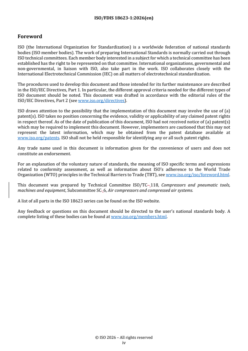
REDLINE ISO/FDIS 18623-1 - Air compressors and compressed air systems — Safety — Part 1: Air compressors

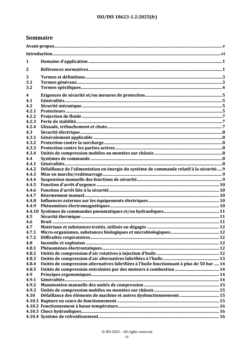
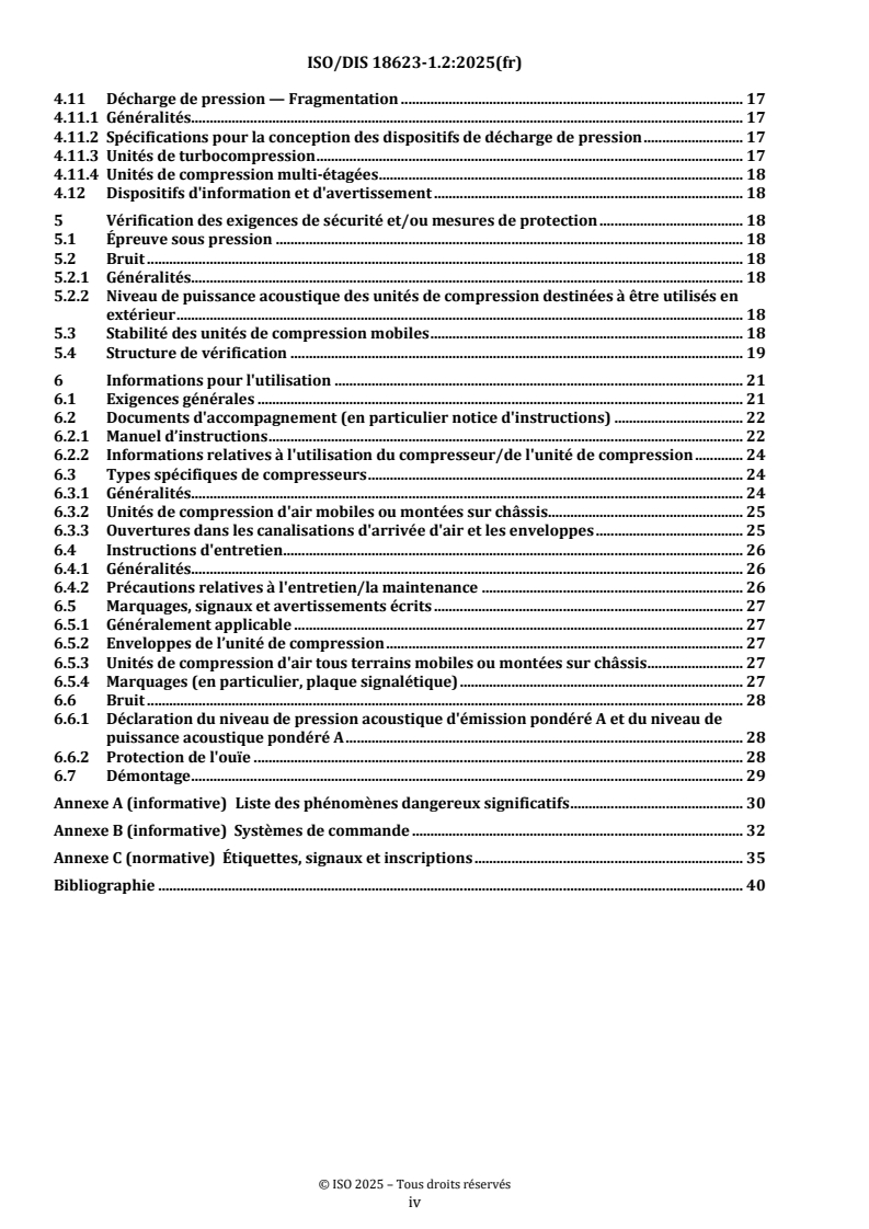
ISO/FDIS 18623-1 - Compresseurs à air et systèmes à air comprimé — Compresseurs à air — Partie 1: Exigences de sécurité des compresseurs à air/11/2025

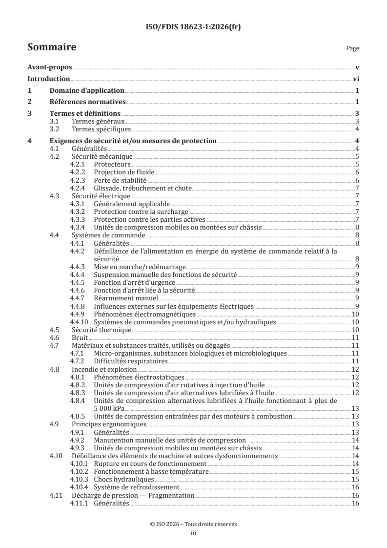
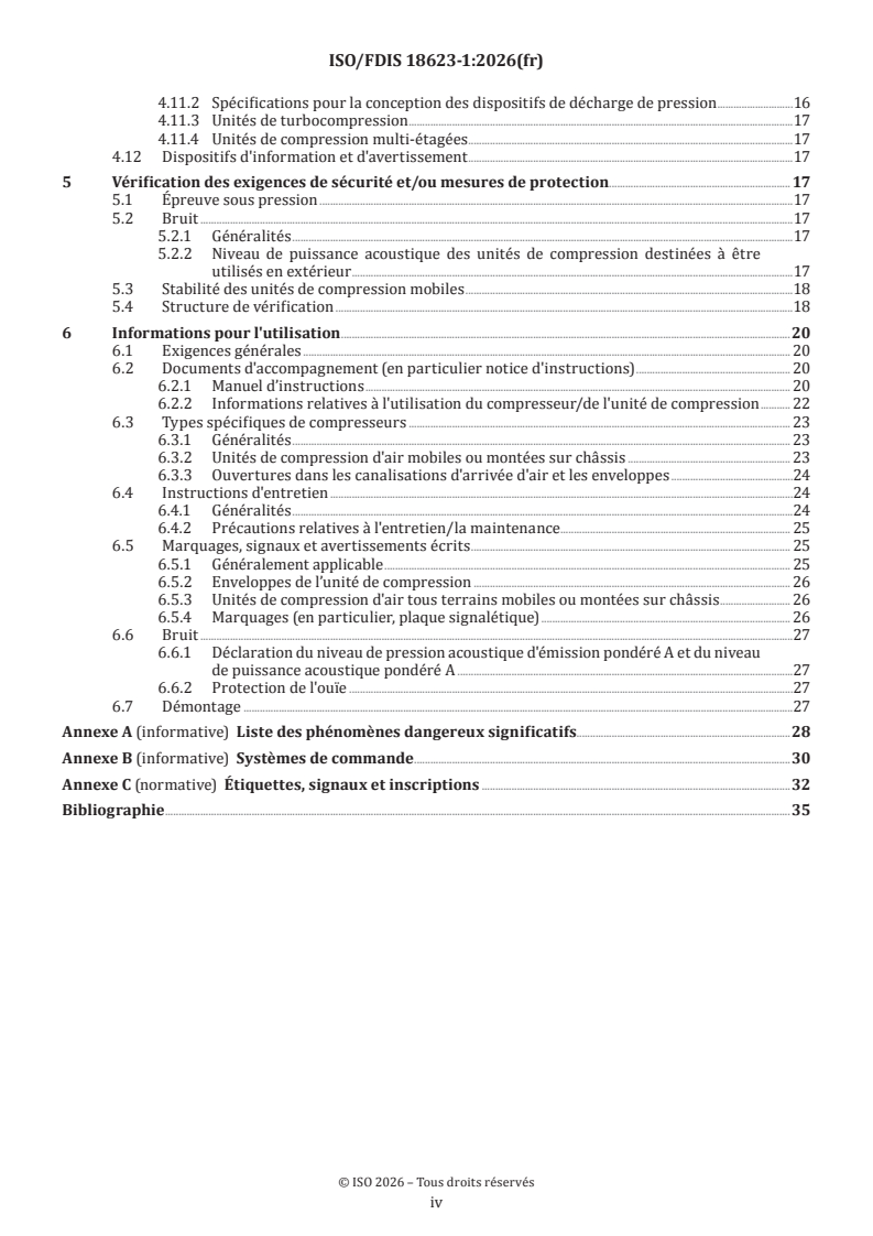
ISO/FDIS 18623-1 - Compresseurs à air et systèmes à air comprimé — Sécurité — Partie 1: Compresseurs à air
Overview
ISO 18623-1: Air Compressors and Compressed Air Systems - Safety - Part 1: Air Compressors is an international standard developed by the International Organization for Standardization (ISO). This standard sets out the safety requirements for compressors and compressor units designed to compress air, nitrogen, or inert gases at operating pressures above 0.5 bar. It covers compressors and compressor units, including associated drive systems and essential components, regardless of the power source, and includes both stationary and portable equipment, such as units fitted to motor vehicles.
This standard is vital for manufacturers, users, and service providers involved in the design, installation, operation, maintenance, and dismantling of air compressors. ISO 18623-1 does not address units for potentially explosive atmospheres or those used for processing petroleum or chemicals within the remit of ISO/TC 67, nor does it apply to compressors manufactured before its publication date.
Key Topics
Significant Hazards and Risk Management
- Identification and mitigation of hazards associated with compressors, as detailed in Annex A.
- Application of risk assessment methodologies in accordance with ISO 12100.
- Consideration of all phases: design, installation, operation, maintenance, and disposal.
Safety Requirements
- Mechanical safety: guarding of moving parts, prevention of fluid injection accidents, and minimizing risks of slips, trips, and falls.
- Electrical safety: compliance with IEC 60204-1 standards, protection from overload and live parts, and requirements for batteries and portable units.
- Control system safety: design of safety-related control systems using ISO 13849-1 or IEC 62061, ensuring safe shutdown, emergency stop functions, and control over electromagnetic interference.
- Thermal safety: guard or warn about hot/cold surfaces, prevent fire hazards.
- Noise reduction: incorporation of noise control measures at the source.
Operational and Maintenance Guidance
- Requirements for instructions handbooks, markings, and warning devices for users.
- Safe procedures for dismantling and disposal of compressor units.
- Special considerations for condensate drainage, ergonomic design, and installations.
Exclusions
- No requirements for performance levels of control systems.
- Excludes compressors for explosive atmospheres or chemical processing.
Applications
Industrial and Commercial Use
- Ensures safer operation of compressors in manufacturing plants, automotive workshops, and construction sites.
- Guidance for system integrators configuring compressed air systems.
Transportation and Mobile Applications
- Covers skid-mounted and portable compressors, including those used in conjunction with vehicles.
- Ensures stability and safety during transportation and usage in variable environments.
Facility Management and Maintenance
- Establishes best practices for maintenance teams to ensure ongoing compliance with safety requirements.
- Helps in the development of comprehensive training for personnel operating or servicing compressors.
Regulatory and Compliance
- Assists manufacturers in meeting international and local regulatory requirements.
- Supports occupational health and safety officers in hazard identification and risk reduction for compressed air systems.
Related Standards
Professionals applying ISO 18623-1 should also be aware of related standards, which provide deeper domain expertise or complementary requirements:
- ISO 12100 - Safety of machinery – General principles for risk assessment and risk reduction.
- ISO 4413 & ISO 4414 - Hydraulic and pneumatic safety requirements.
- ISO 13849-1 - Safety-related parts of control systems – General principles for design.
- IEC 60204-1 - Electrical equipment of machines – General requirements.
- ISO 8573 series - Compressed air – Contaminants and purity classes.
- ISO 14120, ISO 14122, ISO 13857 - Guarding, access, and safety distances for machinery.
- ISO 2151 - Noise test code for compressors.
By referencing ISO 18623-1 and the applicable related standards, organizations can ensure that air compressors and compressed air systems are designed, installed, and maintained with up-to-date safety and operational best practices, reducing risks and supporting regulatory compliance.
Relations
- Effective Date
- 12-Feb-2026
- Effective Date
- 08-Oct-2022
Buy Documents
ISO/FDIS 18623-1 - Air compressors and compressed air systems — Air compressors — Part 1: Safety requirements/29/2025
ISO/FDIS 18623-1 - Air compressors and compressed air systems — Safety — Part 1: Air compressors
REDLINE ISO/FDIS 18623-1 - Air compressors and compressed air systems — Safety — Part 1: Air compressors
ISO/FDIS 18623-1 - Compresseurs à air et systèmes à air comprimé — Compresseurs à air — Partie 1: Exigences de sécurité des compresseurs à air/11/2025
ISO/FDIS 18623-1 - Compresseurs à air et systèmes à air comprimé — Sécurité — Partie 1: Compresseurs à air
Get Certified
Connect with accredited certification bodies for this standard

Institut za varilstvo d.o.o. (Welding Institute)
Slovenia's leading welding institute since 1952. ISO 3834, EN 1090, pressure equipment certification, NDT personnel, welder qualification. Only IIW Au
Sponsored listings
Frequently Asked Questions
ISO 18623-1 is a draft published by the International Organization for Standardization (ISO). Its full title is "Air compressors and compressed air systems — Safety — Part 1: Air compressors". This standard covers: This part 1 of ISO 18623 is applicable to compressors and compressor units having an operating pressure greater than 0,5 bar and designed to compress air, nitrogen or inert gases. This standard deals with all significant hazards, hazardous situations and events relevant to the design, installation, operation, maintenance, dismantling and disposal of compressors and compressor units, when they are used as intended and under conditions of misuse which are reasonably foreseeable by the manufacturer (see Clause 4). This part of ISO 18623 includes under the general term compressor units those machines which comprise: - the compressor; - a drive system; - any component or device which is necessary for operation. This part covers compressors driven by any power media, including battery powered and which are fitted in or used with motor vehicles. The significant hazards dealt with in the standard are identified in Annex A. It does not cover requirements for compressors and compressor units used in potentially explosive atmospheres. It is not applicable to compressors and compressor units which are manufactured before the date of publication of this standard. It does not cover compressors and compressor units for processing petroleum, petrochemicals, or chemicals within the scope of ISO/TC 67.
This part 1 of ISO 18623 is applicable to compressors and compressor units having an operating pressure greater than 0,5 bar and designed to compress air, nitrogen or inert gases. This standard deals with all significant hazards, hazardous situations and events relevant to the design, installation, operation, maintenance, dismantling and disposal of compressors and compressor units, when they are used as intended and under conditions of misuse which are reasonably foreseeable by the manufacturer (see Clause 4). This part of ISO 18623 includes under the general term compressor units those machines which comprise: - the compressor; - a drive system; - any component or device which is necessary for operation. This part covers compressors driven by any power media, including battery powered and which are fitted in or used with motor vehicles. The significant hazards dealt with in the standard are identified in Annex A. It does not cover requirements for compressors and compressor units used in potentially explosive atmospheres. It is not applicable to compressors and compressor units which are manufactured before the date of publication of this standard. It does not cover compressors and compressor units for processing petroleum, petrochemicals, or chemicals within the scope of ISO/TC 67.
ISO 18623-1 is classified under the following ICS (International Classification for Standards) categories: 23.140 - Compressors and pneumatic machines. The ICS classification helps identify the subject area and facilitates finding related standards.
ISO 18623-1 has the following relationships with other standards: It is inter standard links to prEN ISO 18623-1, ISO 10448:2021. Understanding these relationships helps ensure you are using the most current and applicable version of the standard.
ISO 18623-1 is available in PDF format for immediate download after purchase. The document can be added to your cart and obtained through the secure checkout process. Digital delivery ensures instant access to the complete standard document.
Standards Content (Sample)
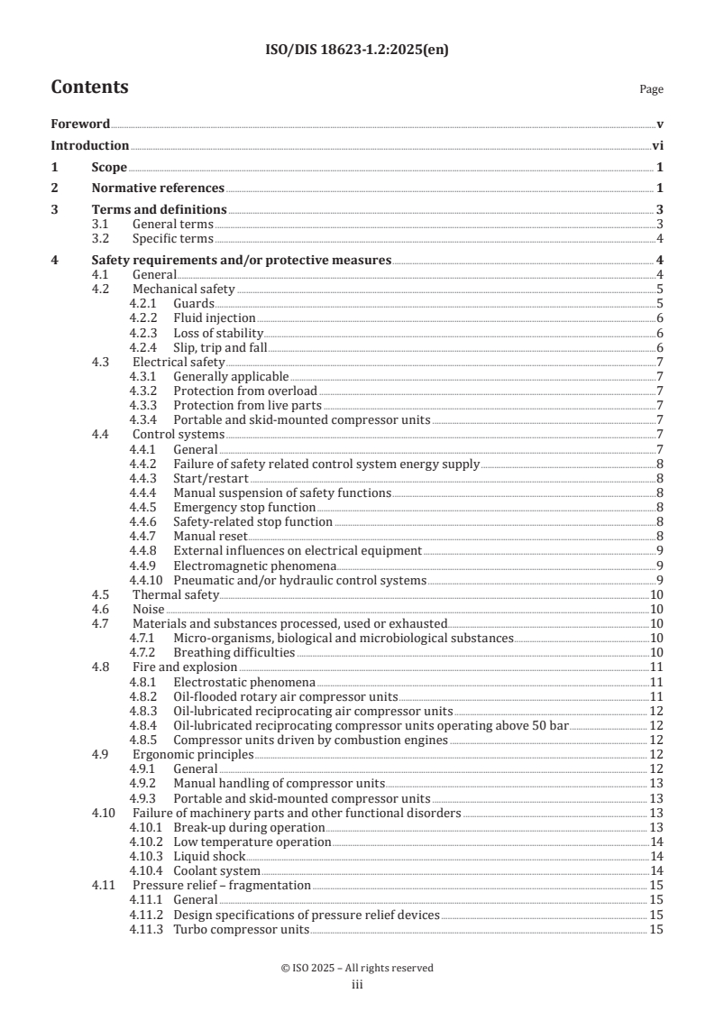
DRAFT
International
Standard
ISO/DIS 18623-1.2
ISO/TC 118/SC 6
Air compressors and compressed
Secretariat: SIS
air systems — Air compressors —
Voting begins on:
Part 1: 2025-08-12
Safety requirements
Voting terminates on:
2025-10-07
ICS: 23.140
THIS DOCUMENT IS A DRAFT CIRCULATED
FOR COMMENTS AND APPROVAL. IT
IS THEREFORE SUBJECT TO CHANGE
AND MAY NOT BE REFERRED TO AS AN
INTERNATIONAL STANDARD UNTIL
PUBLISHED AS SUCH.
IN ADDITION TO THEIR EVALUATION AS
BEING ACCEPTABLE FOR INDUSTRIAL,
TECHNOLOGICAL, COMMERCIAL AND
USER PURPOSES, DRAFT INTERNATIONAL
STANDARDS MAY ON OCCASION HAVE TO
This document has not been edited by the ISO Central Secretariat.
BE CONSIDERED IN THE LIGHT OF THEIR
POTENTIAL TO BECOME STANDARDS TO
WHICH REFERENCE MAY BE MADE IN
NATIONAL REGULATIONS.
RECIPIENTS OF THIS DRAFT ARE INVITED
TO SUBMIT, WITH THEIR COMMENTS,
NOTIFICATION OF ANY RELEVANT PATENT
RIGHTS OF WHICH THEY ARE AWARE AND TO
PROVIDE SUPPORTING DOCUMENTATION.
Reference number
ISO/DIS 18623-1.2:2025(en)
DRAFT
ISO/DIS 18623-1.2:2025(en)
International
Standard
ISO/DIS 18623-1.2
ISO/TC 118/SC 6
Air compressors and compressed
Secretariat: SIS
air systems — Air compressors —
Voting begins on:
Part 1:
Safety requirements
Voting terminates on:
ICS: 23.140
THIS DOCUMENT IS A DRAFT CIRCULATED
FOR COMMENTS AND APPROVAL. IT
IS THEREFORE SUBJECT TO CHANGE
AND MAY NOT BE REFERRED TO AS AN
INTERNATIONAL STANDARD UNTIL
PUBLISHED AS SUCH.
IN ADDITION TO THEIR EVALUATION AS
BEING ACCEPTABLE FOR INDUSTRIAL,
© ISO 2025
TECHNOLOGICAL, COMMERCIAL AND
USER PURPOSES, DRAFT INTERNATIONAL
All rights reserved. Unless otherwise specified, or required in the context of its implementation, no part of this publication may
STANDARDS MAY ON OCCASION HAVE TO
be reproduced or utilized otherwise in any form or by any means, electronic or mechanical, including photocopying, or posting on
This document has not been edited by the ISO Central Secretariat. BE CONSIDERED IN THE LIGHT OF THEIR
the internet or an intranet, without prior written permission. Permission can be requested from either ISO at the address below
POTENTIAL TO BECOME STANDARDS TO
WHICH REFERENCE MAY BE MADE IN
or ISO’s member body in the country of the requester.
NATIONAL REGULATIONS.
ISO copyright office
RECIPIENTS OF THIS DRAFT ARE INVITED
CP 401 • Ch. de Blandonnet 8
TO SUBMIT, WITH THEIR COMMENTS,
CH-1214 Vernier, Geneva
NOTIFICATION OF ANY RELEVANT PATENT
Phone: +41 22 749 01 11
RIGHTS OF WHICH THEY ARE AWARE AND TO
PROVIDE SUPPORTING DOCUMENTATION.
Email: copyright@iso.org
Website: www.iso.org
Published in Switzerland Reference number
ISO/DIS 18623-1.2:2025(en)
ii
ISO/DIS 18623-1.2:2025(en)
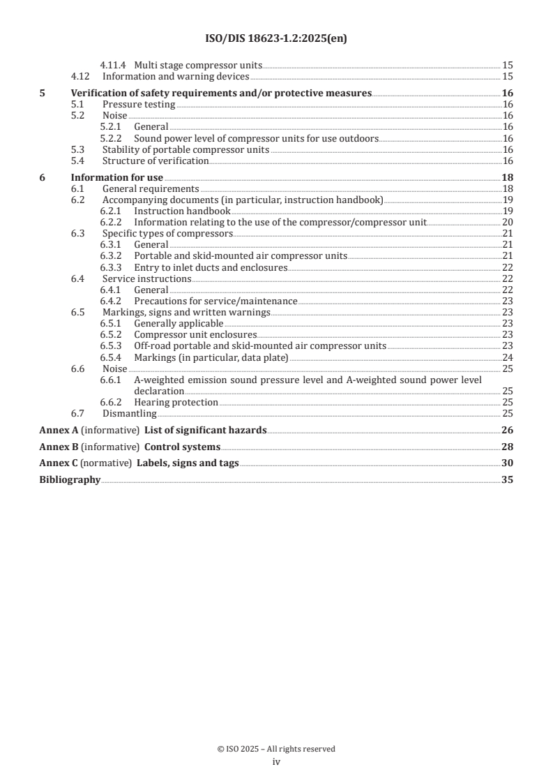
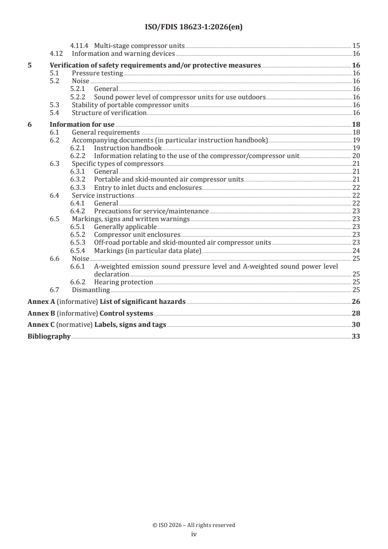
Contents Page
Foreword .v
Introduction .vi
1 Scope . 1
2 Normative references . 1
3 Terms and definitions . 3
3.1 General terms .3
3.2 Specific terms .4
4 Safety requirements and/or protective measures . 4
4.1 General .4
4.2 Mechanical safety .5
4.2.1 Guards .5
4.2.2 Fluid injection .6
4.2.3 Loss of stability .6
4.2.4 Slip, trip and fall .6
4.3 Electrical safety .7
4.3.1 Generally applicable .7
4.3.2 Protection from overload .7
4.3.3 Protection from live parts .7
4.3.4 Portable and skid-mounted compressor units .7
4.4 Control systems .7
4.4.1 General .7
4.4.2 Failure of safety related control system energy supply .8
4.4.3 Start/restart .8
4.4.4 Manual suspension of safety functions .8
4.4.5 Emergency stop function .8
4.4.6 Safety-related stop function .8
4.4.7 Manual reset .8
4.4.8 External influences on electrical equipment .9
4.4.9 Electromagnetic phenomena .9
4.4.10 Pneumatic and/or hydraulic control systems .9
4.5 Thermal safety.10
4.6 Noise .10
4.7 Materials and substances processed, used or exhausted.10
4.7.1 Micro-organisms, biological and microbiological substances .10
4.7.2 Breathing difficulties .10
4.8 Fire and explosion .11
4.8.1 Electrostatic phenomena .11
4.8.2 Oil-flooded rotary air compressor units .11
4.8.3 Oil-lubricated reciprocating air compressor units . 12
4.8.4 Oil-lubricated reciprocating compressor units operating above 50 bar . 12
4.8.5 Compressor units driven by combustion engines . 12
4.9 Ergonomic principles . 12
4.9.1 General . 12
4.9.2 Manual handling of compressor units . 13
4.9.3 Portable and skid-mounted compressor units . 13
4.10 Failure of machinery parts and other functional disorders . 13
4.10.1 Break-up during operation . 13
4.10.2 Low temperature operation .14
4.10.3 Liquid shock .14
4.10.4 Coolant system .14
4.11 Pressure relief – fragmentation . 15
4.11.1 General . 15
4.11.2 Design specifications of pressure relief devices . 15
4.11.3 Turbo compressor units . 15
iii
ISO/DIS 18623-1.2:2025(en)
4.11.4 Multi stage compressor units. 15
4.12 Information and warning devices . 15
5 Verification of safety requirements and/or protective measures .16
5.1 Pressure testing .16
5.2 Noise .16
5.2.1 General .16
5.2.2 Sound power level of compressor units for use outdoors.16
5.3 Stability of portable compressor units .16
5.4 Structure of verification.16
6 Information for use .18
6.1 General requirements .18
6.2 Accompanying documents (in particular, instruction handbook) .19
6.2.1 Instruction handbook .19
6.2.2 Information relating to the use of the compressor/compressor unit . 20
6.3 Specific types of compressors . .21
6.3.1 General .21
6.3.2 Portable and skid-mounted air compressor units .21
6.3.3 Entry to inlet ducts and enclosures . 22
6.4 Service instructions . 22
6.4.1 General . 22
6.4.2 Precautions for service/maintenance . 23
6.5 Markings, signs and written warnings . 23
6.5.1 Generally applicable . 23
6.5.2 Compressor unit enclosures . 23
6.5.3 Off-road portable and skid-mounted air compressor units . 23
6.5.4 Markings (in particular, data plate) .24
6.6 Noise . 25
6.6.1 A-weighted emission sound pressure level and A-weighted sound power level
declaration . 25
6.6.2 Hearing protection . 25
6.7 Dismantling . 25
Annex A (informative) List of significant hazards .26
Annex B (informative) Control systems .28
Annex C (normative) Labels, signs and tags .30
Bibliography .35
iv
ISO/DIS 18623-1.2:2025(en)
Foreword
ISO (the International Organization for Standardization) is a worldwide federation of national standards
bodies (ISO member bodies). The work of preparing International Standards is normally carried out through
ISO technical committees. Each member body interested in a subject for which a technical committee
has been established has the right to be represented on that committee. International organizations,
governmental and non-governmental, in liaison with ISO, also take part in the work. ISO collaborates closely
with the International Electrotechnical Commission (IEC) on all matters of electrotechnical standardization.
The procedures used to develop this document and those intended for its further maintenance are described
in the ISO/IEC Directives, Part 1. In particular, the different approval criteria needed for the different types
of ISO document should be noted. This document was drafted in accordance with the editorial rules of the
ISO/IEC Directives, Part 2 (see www.iso.org/directives).
ISO draws attention to the possibility that the implementation of this document may involve the use of (a)
patent(s). ISO takes no position concerning the evidence, validity or applicability of any claimed patent
rights in respect thereof. As of the date of publication of this document, ISO had not received notice of (a)
patent(s) which may be required to implement this document. However, implementers are cautioned that
this may not represent the latest information, which may be obtained from the patent database available at
www.iso.org/patents. ISO shall not be held responsible for identifying any or all such patent rights.
Any trade name used in this document is information given for the convenience of users and does not
constitute an endorsement.
For an explanation of the voluntary nature of standards, the meaning of ISO specific terms and expressions
related to conformity assessment, as well as information about ISO's adherence to the World Trade
Organization (WTO) principles in the Technical Barriers to Trade (TBT), see www.iso.org/iso/foreword.html.
This document was prepared by Technical Committee ISO/TC 118, Compressors and pneumatic tools,
machines and equipment, Subcommittee SC 6, Air compressors and compressed air systems.
A list of all parts in the ISO 18623 series can be found on the ISO website.
Any feedback or questions on this document should be directed to the user’s national standards body. A
complete listing of these bodies can be found at www.iso.org/members.html.
v
ISO/DIS 18623-1.2:2025(en)
Introduction
This document is a type-C standard as stated in ISO 12100.
This document is of relevance, in particular, for the following stakeholder groups representing the market
players with regard to machinery safety:
— machine manufacturers (small, medium and large enterprises);
— health and safety bodies (regulators, accident prevention organisations, market surveillance etc.)
Others can be affected by the level of machinery safety achieved with the means of the document by the
above-mentioned stakeholder groups:
— machine users/employers (small, medium and large enterprises);
— machine users/employees (e.g. trade unions, organizations for people with special needs);
— service providers, e. g. for maintenance (small, medium and large enterprises);
— consumers (in case of machinery intended for use by consumers).
The above-mentioned stakeholder groups have been given the possibility to participate at the drafting
process of this document.
The machinery concerned and the extent to which hazards, hazardous situations or hazardous events are
covered are indicated in the Scope of this document.
When requirements of this type-C standard are different from those which are stated in type-A or type-B
standards, the requirements of this type-C standard take precedence over the requirements of the other
standards for machines that have been designed and built according to the requirements of this type-C
standard.
vi
DRAFT International Standard ISO/DIS 18623-1.2:2025(en)
Air compressors and compressed air systems — Air
compressors —
Part 1:
Safety requirements
1 Scope
This document is applicable to compressors, partially completed compressor units and compressor units
having an operating pressure greater than 0,5 bar and designed to compress air, nitrogen or inert gases.
This document deals with all significant hazards, hazardous situations and events relevant to the design,
installation, operation, maintenance, dismantling and disposal of compressors and compressor units
when they are used as intended and under conditions of misuse which are reasonably foreseeable by the
manufacturer (see Clause 4 of this document).
This document includes under the general term compressor units those machines which comprise:
— the compressor;
— a drive system;
— any component or device which is necessary for operation.
This document covers compressors driven by any power media, including battery powered and which are
fitted in or used with motor vehicles.
The significant hazards dealt with in this document are identified in Annex A.
This document does not cover requirements for compressors and compressor units used in potentially
explosive atmospheres.
This document is not applicable to compressors and compressor units which are manufactured before the
date of publication of this document.
This document does not cover compressors and compressor units for processing petroleum, petrochemicals,
or chemicals within the scope of ISO/TC 67.
This document does not give performance levels or safety integrity levels for safety related parts of control
systems.
2 Normative references
The following documents are referred to in the text in such a way that some or all of their content constitutes
requirements of this document. For dated references, only the edition cited applies. For undated references,
the latest edition of the referenced document (including any amendments) applies.
ISO 2151, Acoustics — Noise test code for compressors and vacuum pumps — Engineering method (Grade 2)
ISO 3857-1, Compressors, pneumatic tools and machines — Vocabulary — Part 1: General
ISO 3857-2, Compressors, pneumatic tools and machines — Vocabulary — Part 2: Compressors
ISO 4126-1:2013, Safety devices for protection against excessive pressure — Part 1: Safety valves
ISO/DIS 18623-1.2:2025(en)
ISO 4126-1:2013/Amd 1:2016, Safety devices for protection against excessive pressure — Part 1: Safety valves
— Amendment 1
ISO 4413, Hydraulic fluid power — General rules and safety requirements for systems and their components
ISO 4414, Pneumatic fluid power — General rules and safety requirements for systems and their components
ISO 8573-1, Compressed air — Part 1: Contaminants and purity classes
ISO 8573-2, Compressed air — Contaminant measurement — Part 2: Oil aerosol content
ISO 8573-3, Compressed air — Part 3: Test methods for measurement of humidity
ISO 8573-4, Compressed air — Contaminant measurement — Part 4: Particle content
ISO 12100, Safety of machinery — General principles for design — Risk assessment and risk reduction
ISO 13766-1, Earth-moving and building construction machinery — Electromagnetic compatibility (EMC)
of machines with internal electrical power supply — Part 1: General EMC requirements under typical
electromagnetic environmental conditions
ISO 13766-2, Earth-moving and building construction machinery — Electromagnetic compatibility (EMC) of
machines with internal electrical power supply — Part 2: Additional EMC requirements for functional safety
ISO 13849-1, Safety of machinery — Safety-related parts of control systems — Part 1: General principles for design
ISO 13850, Safety of machinery — Emergency stop function — Principles for design
ISO 13857, Safety of machinery — Safety distances to prevent hazard zones being reached by upper and lower limbs
ISO 14120, Safety of machinery — Guards — General requirements for the design and construction of fixed and
movable guards
ISO 14122-1, Safety of machinery — Permanent means of access to machinery — Part 1: Choice of fixed means
and general requirements of access
ISO 14122-2, Safety of machinery — Permanent means of access to machinery — Part 2: Working platforms and
walkways
ISO 14122-3, Safety of machinery — Permanent means of access to machinery — Part 3: Stairs, stepladders and
guard-rails
ISO 14122-4, Safety of machinery — Permanent means of access to machinery — Part 4: Fixed ladders
ISO 14123-1, Safety of machinery — Reduction of risks to health resulting from hazardous substances emitted
by machinery — Part 1: Principles and specifications for machinery manufacturers
ISO 15534-1, Ergonomic design for the safety of machinery — Part 1: Principles for determining the dimensions
required for openings for whole-body access into machinery
IEC 60204-1, Safety of machinery - Electrical equipment of machines - Part 1: General requirements
IEC 60204-1:2016/AMD1:2021, Amendment 1 - Safety of machinery - Electrical equipment of machines - Part 1:
General requirements
IEC 60204-11, Safety of machinery - Electrical equipment of machines - Part 11: Requirements for equipment for
voltages above 1 000 V AC or 1 500 V DC and not exceeding 36 kV
IEC 60417-DB-12M:2002, Graphical Symbols For Use On Equipment - 12-Month Subscription To Online Database
Comprising All Graphical Symbols Published In IEC 60417
IEC 61000-6-2, Electromagnetic compatibility (EMC) - Part 6-2: Generic standards - Immunity standard for
industrial environments
ISO/DIS 18623-1.2:2025(en)
IEC 61000-6-4, Electromagnetic compatibility (EMC) - Part 6-4: Generic standards - Emission standard for
industrial environments
IEC 61310-2:2007, Safety of machinery - Indication, marking and actuation - Part 2: Requirements for marking
IEC 62061, Safety of machinery - Functional safety of safety-related control systems
3 Terms and definitions
For the purposes of this document, the terms and definitions given in ISO 12100, ISO 3857-1, ISO 3857-2 and
the following apply.
ISO and IEC maintain terminology databases for use in standardization at the following addresses:
— ISO Online browsing platform: available at https:// www .iso .org/ obp
— IEC Electropedia: available at https:// www .electropedia .org/
3.1 General terms
3.1.1
compressor
part of a compressor unit (3.1.3) that compresses a gas or vapour media to a pressure higher than that at the inlet
3.1.2
Partially completed compressor unit
unit that comprises the compressor (3.1.1), components and sub-assemblies that is almost a compressor unit
but cannot perform function on its own
3.1.3
compressor unit
unit that comprises the compressor (3.1.1), a drive system (3.1.4) and any component or device which is
necessary for operation
3.1.4
drive system
system that consists of a prime mover and coupling mechanism
Note 1 to entry: Prime mover may be an electric motor, steam engine (turbine), etc.
Note 2 to entry: Coupling mechanism may be a drive belt, shaft, gears, etc.
3.1.5
inert gas
chemically inactive gas which retains this characteristic even at elevated pressures
3.1.6
pressure
pressure relative to atmospheric pressure, i.e. gauge pressure
Note 1 to entry: In many cases, this is referred to as effective pressure.
Note 2 to entry: The unit bar for pressure is used. 1 bar = 100 kPa.
3.1.7
liquid shock
excessive force resulting from an attempt to compress incompressible media
ISO/DIS 18623-1.2:2025(en)
3.1.8
maximum allowable pressure
maximum pressure for which the compressor (3.1.1) or compressor unit (3.1.3) is designed, as specified by
the manufacturer
Note 1 to entry: This is also identified as maximum allowable working pressure.
3.1.9
normal operating conditions
conditions considered to be when the compressor (3.1.1) is properly maintained and operated within
admissible limits, in particular; ambient temperature, as specified by the manufacturer when compressing
the specified media
3.2 Specific terms
3.2.1
air compressor
compressor (3.1.1) intended for compression of air, nitrogen or inert gases (3.1.5)
3.2.2
portable and skid mounted compressor
3.2.2.1
portable compressor unit
compressor unit (3.1.3) which is wheel-mounted and can be towed on- and off-site
3.2.2.2
skid-mounted compressor unit
compressor unit (3.1.3) which is mounted on skids and which can be towed short distances on-site or
transported
3.2.2.3
gross mass
maximum specified mass of a skid-mounted or portable compressor unit (3.2.2.1) (including tools, equipment
and fuel)
Note 1 to entry: Tools and equipment includes for example concrete breakers, picks and hoses likely to be carried for a
typical working application.
3.2.3
water-injected compressor
compressor (3.1.1) design in which the compressed media and the water are mixed
4 Safety requirements and/or protective measures
4.1 General
The machine shall comply with the following safety requirements and/or protective measures and be
verified in accordance with Clause 5. In addition, the machine shall be designed according to the principles
of ISO 12100 for relevant, but not necessarily significant hazards, which are not dealt with by this document.
When choices are necessary for the application of type B standards referred to in this document, i.e. listed in
Clause 2, the manufacturer shall carry out an appropriate risk assessment for making these choices.
The measures adopted to conform with the requirements of this clause shall take account of the state-of-
the-art when more effective technical means become available.
ISO/DIS 18623-1.2:2025(en)
4.2 Mechanical safety
4.2.1 Guards
4.2.1.1 General
When fixed guards have to be removed for periodic maintenance or repair, their fixing systems shall remain
attached to the guard or machinery when the guards are removed.
4.2.1.2 Cutting and severing, friction and abrasion
All moving parts shall be enclosed within the permanent compressor casing or compressor unit cover,
enclosure or canopy. When this is not possible, separate guards shall be provided to prevent contact with
all rotating and reciprocating parts to minimize the risk of cutting and severing, friction and abrasion to
personnel in accordance with ISO 14120 and ISO 13857 for safety distances.
4.2.1.3 Bodily contact
4.2.1.4 Deflections shall not result in contact with moving parts or permanent deformation of the
guard. The provisions for rigidity of guards shall be in accordance with ISO 14120.Ejection of parts
Moving parts shall be designed and mounted in such a way that in all foreseeable modes of operation the
risk of ejection of parts is minimised. Where the risk assessment identifies a remaining risk of ejection, e.g. a
drive belt from a belt driven compressor, then the impact resistance for guarding shall be in accordance with
ISO 14120.
4.2.1.5 Entry to inlet ducts and enclosures
Atmospheric inlets and inspection openings in inlets shall be provided with protective devices, so that
persons cannot be drawn in or danger zones reached when the compressor is running. For this purpose, any
openings shall comply with ISO 13857 for upper and lower limbs, when applicable.
Openings giving access to moving parts creating a risk of trapping or shearing shall be prevented by either:
— total enclosure with an interlocked means of access, e.g. door, cover, etc. such that the compressor is shut
down when the access is opened and cannot be started until the access is closed; or
— total enclosure without interlock when access to moving parts, e.g. fan belts, barring gear, timing marks,
etc., shall be prevented by local guarding; or
— without total enclosure when access to moving parts, e.g. fan belts, barring gear, timing marks, etc., shall
be prevented by local guarding.
Where service, maintenance or inspection activities require access within the enclosure doors whilst
the compressor is still operational, consideration shall be given to the additional hazards created and the
measures taken shall be in accordance with ISO 12100. The provisions of 6.3.3 shall also be applied.
Where whole body access is required to inlet ducts and enclosures for service, maintenance or inspection
the provisions of ISO 15534-1 shall be followed when determining the minimum dimensions of openings for
such whole-body access.
Where whole body access is required to inlet ducts for service, maintenance or inspection, a guard shall be
fitted to prevent unauthorised access. The guard shall be:
— interlocked such that when the guard is opened the compressor is shut-down and cannot be restarted
until the guard is closed; and
— unintentional closure of the guard is prevented by the use of a trapped key interlock or a padlock where
the only key for the trapped key or the padlock can be retained by the person entering the inlet duct.
ISO/DIS 18623-1.2:2025(en)
Where it is foreseeable that the compressor will remain operational during whole body access to the inlet
duct for service, maintenance or inspection, the design of the inlet duct shall be such that the air flow at the
entrance to the inlet duct shall be ≤2,5 m/s and in addition a protective grid shall be installed inside the duct
to prevent personnel being drawn into the compressor.
A safe system of work shall also be identified in accordance with 6.4.1.
4.2.2 Fluid injection
The risk of fluid (gas or liquid) injection into the human body shall be minimized by:
— designing and supporting integral pipework, hoses and auxiliaries to withstand vibration, thermal
expansion and their own mass, foreseeable external forces, influence of contaminants and external
chemical substances;
— ensuring that all piping which is in a position likely to be damaged is protected, robust and sufficiently
supported, but shall be free to move with changing temperature;
— ensuring that the design of oil/coolant filler plugs does not allow the dangerous release of fluid, e.g. by
means of preventing the removal of the filler plug under pressure or an effective warning system;
— the design and location of pressure vents and drains, shall take account of the velocity of air, gas, vapour
or liquid likely to be discharged.
4.2.3 Loss of stability
4.2.3.1 Generally applicable
Compressor units shall be in accordance with ISO 12100.
4.2.3.2 Portable and skid-mounted compressor units
The centre of gravity, mainly associated with the engine/compressor combination shall be low enough to
ensure that the compressor unit remains stable, without tipping or slipping, when used within intended limits.
The provisions of 6.3.2 shall be applied to indicate the intended limits.
Tyres of a portable compressor unit shall be rated to carry the maximum gross mass of the portable
compressor unit at the highest towing speed the compressor unit is intended for. All tyres shall be of the
same construction.
The support leg or jockey wheel shall be capable of supporting the gross nose weight of the portable
compressor unit as defined in the instruction handbook. It shall be possible to securely lock it in the support
and towing positions by, for example, a clamping system or removable pin in locating holes.
The jockey wheel device shall be positively retained in the draw bar in the event of the operator leaving it
unlocked.
NOTE Portable compressor units used on-road are also subject to regulations related to motor vehicles and their
trailers.
4.2.4 Slip, trip and fall
If access to elevated areas around a compressor unit is necessary and is an integral part of a compressor unit
then these access areas shall be in accordance with ISO 12100. Where such access is provided, permanent
means of access to working platforms, walkways, fixed ladders and stairways shall be in accordance with
ISO 14122-1, ISO 14122-2, ISO 14122-3 and ISO 14122-4.
If access to elevated areas is required and is not an integral part of the compressor unit, appropriate
installation instructions shall be given in the instruction handbook.
ISO/DIS 18623-1.2:2025(en)
4.3 Electrical safety
4.3.1 Generally applicable
The electrical equipment of a compressor unit shall be in accordance with IEC 60204-1 and/or IEC 60204-11
as appropriate.
4.3.2 Protection from overload
Where the compressor unit is not fitted with an over-current protection of the power circuit due to it being
installed outside the compressor enclosure on site, the provisions of 6.2.1.3.1 shall be followed.
4.3.3 Protection from live parts
Where the compressor unit is not fitted with an electrical disconnecting device, the provisions of 6.2.1.3.2
shall be followed.
Electrical and instrument cabling shall:
— be adequately secured and protected;
— not be in contact with hot surfaces;
— have adequate electrical insulation.
Electrical and instrument cabling shall be in accordance with IEC 60204-1.
4.3.4 Portable and skid-mounted compressor units
4.3.4.1 General
A suitable over-current protection device, e.g. fuse, shall be provided in the electrical installation to protect
the wiring harness and the electric equipment. This excludes the pre-heat, starting and charging circuits.
Where fuses are provided as over-current protection devices, a type readily available in the country of use
shall be selected, or arrangements made for the supply of spare parts.
4.3.4.2 Batteries
Batteries shall be of the type with lifting handles or with lifting points. They shall be mounted and firmly
secured so there is no risk of electrolyte splashing on personnel and surrounding equipment.
4.4 Control systems
4.4.1 General
Effective control system design shall be in accordance with ISO 12100, IEC 60204-1. Where software or
a programmable device is used to provide control and safety functions in all its operating modes, it shall
comply with this section and shall be verified and documented, including updates and revisions. Safety
related parts of control systems can be part of, but not limited to, start, stop, emergency stop, interlocking,
high air temperature, and over-pressure control functions.
Safety systems shall be designed and evaluated using the methods of functional safety as defined in one of
the following standards: ISO 13849-1 or IEC 62061. An introduction to the methods of functional safety is
given in Annex B.
The safety related controlled shutdown system and the emergency shutdown system can be initiated by
different safety functions which may require different performance levels (PL) in accordance to ISO 13849-1
or safety integrity levels (SIL) in accordance with IEC 62061.
ISO/DIS 18623-1.2:2025(en)
The safety related controlled shutdown system shall comply with the highest required performance level
(PL) or safety integrity level (SIL) of all the safety functions initiating the safety related controlled shutdown.
The emergency shutdown system shall comply with the highest required performance level (PL) or safety
integrity level (SIL) of all the safety functions initiating the emergency shutdown.
The identification of the required PL and/or SIL is the responsibility of the manufacturer and is outside the
scope of this standard.
The safety related controlled shutdown system and the emergency shutdown system may be combined in
one system.
4.4.2 Failure of safety related control system energy supply
The system design shall be such that failure of the control system energy supply shall not result in a
hazardous situation during the time of the failure or when the control system energy supply is reinstated. In
case of failure of the energy supply of the safety related control system or a part of the safety related control
system the maximum safety performance of the safety related control system shall be carried out.
NOTE Possible energy sources are e.g. electrical energy, hydraulic energy, compressed air, steam, gas.
4.4.3 Start/restart
A protective device to prevent unintended start/restart shall be provided.
The requirements for a start and restart shall be in accordance with ISO 13849-1 and, if required, with
ISO 12100.
Compressor units that are fitted with automatic or remote start controls shall follow the provisions of 6.2.2
d) and e).
Where maintenance/service requires the suspension of safet
...
FINAL DRAFT
International
Standard
ISO/FDIS 18623-1
ISO/TC 118/SC 6
Air compressors and compressed
Secretariat: SIS
air systems — Safety —
Voting begins on:
2026-05-05
Part 1:
Air compressors
Voting terminates on:
2026-06-30
Compresseurs à air et systèmes à air comprimé — Sécurité —
Partie 1: Compresseurs à air
RECIPIENTS OF THIS DRAFT ARE INVITED TO SUBMIT,
WITH THEIR COMMENTS, NOTIFICATION OF ANY
RELEVANT PATENT RIGHTS OF WHICH THEY ARE AWARE
AND TO PROVIDE SUPPOR TING DOCUMENTATION.
IN ADDITION TO THEIR EVALUATION AS
BEING ACCEPTABLE FOR INDUSTRIAL, TECHNO-
LOGICAL, COMMERCIAL AND USER PURPOSES, DRAFT
INTERNATIONAL STANDARDS MAY ON OCCASION HAVE
TO BE CONSIDERED IN THE LIGHT OF THEIR POTENTIAL
TO BECOME STAN DARDS TO WHICH REFERENCE MAY BE
MADE IN NATIONAL REGULATIONS.
Reference number
ISO/FDIS 18623-1:2026(en) © ISO 2026
FINAL DRAFT
ISO/FDIS 18623-1:2026(en)
International
Standard
ISO/FDIS 18623-1
ISO/TC 118/SC 6
Air compressors and compressed
Secretariat: SIS
air systems — Safety —
Voting begins on:
Part 1:
Air compressors
Voting terminates on:
Compresseurs à air et systèmes à air comprimé — Sécurité —
Partie 1: Compresseurs à air
RECIPIENTS OF THIS DRAFT ARE INVITED TO SUBMIT,
WITH THEIR COMMENTS, NOTIFICATION OF ANY
RELEVANT PATENT RIGHTS OF WHICH THEY ARE AWARE
AND TO PROVIDE SUPPOR TING DOCUMENTATION.
© ISO 2026
IN ADDITION TO THEIR EVALUATION AS
All rights reserved. Unless otherwise specified, or required in the context of its implementation, no part of this publication may
BEING ACCEPTABLE FOR INDUSTRIAL, TECHNO-
LOGICAL, COMMERCIAL AND USER PURPOSES, DRAFT
be reproduced or utilized otherwise in any form or by any means, electronic or mechanical, including photocopying, or posting on
INTERNATIONAL STANDARDS MAY ON OCCASION HAVE
the internet or an intranet, without prior written permission. Permission can be requested from either ISO at the address below
TO BE CONSIDERED IN THE LIGHT OF THEIR POTENTIAL
or ISO’s member body in the country of the requester.
TO BECOME STAN DARDS TO WHICH REFERENCE MAY BE
MADE IN NATIONAL REGULATIONS.
ISO copyright office
CP 401 • Ch. de Blandonnet 8
CH-1214 Vernier, Geneva
Phone: +41 22 749 01 11
Email: copyright@iso.org
Website: www.iso.org
Published in Switzerland Reference number
ISO/FDIS 18623-1:2026(en) © ISO 2026
ii
ISO/FDIS 18623-1:2026(en)
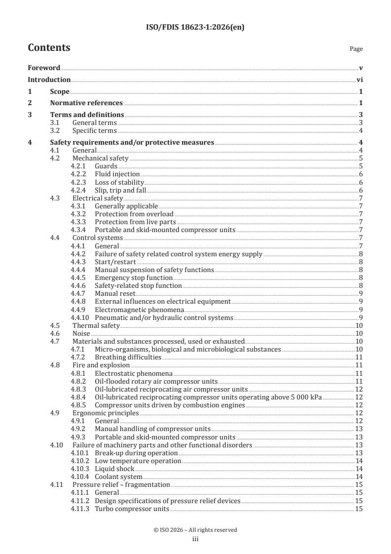
Contents Page
Foreword .v
Introduction .vi
1 Scope . 1
2 Normative references . 1
3 Terms and definitions . 3
3.1 General terms .3
3.2 Specific terms .4
4 Safety requirements and/or protective measures . 4
4.1 General .4
4.2 Mechanical safety .5
4.2.1 Guards .5
4.2.2 Fluid injection .6
4.2.3 Loss of stability .6
4.2.4 Slip, trip and fall .6
4.3 Electrical safety .7
4.3.1 Generally applicable .7
4.3.2 Protection from overload .7
4.3.3 Protection from live parts .7
4.3.4 Portable and skid-mounted compressor units .7
4.4 Control systems .7
4.4.1 General .7
4.4.2 Failure of safety related control system energy supply .8
4.4.3 Start/restart .8
4.4.4 Manual suspension of safety functions .8
4.4.5 Emergency stop function .8
4.4.6 Safety-related stop function .8
4.4.7 Manual reset .9
4.4.8 External influences on electrical equipment .9
4.4.9 Electromagnetic phenomena .9
4.4.10 Pneumatic and/or hydraulic control systems .9
4.5 Thermal safety.10
4.6 Noise .10
4.7 Materials and substances processed, used or exhausted.10
4.7.1 Micro-organisms, biological and microbiological substances .10
4.7.2 Breathing difficulties .11
4.8 Fire and explosion .11
4.8.1 Electrostatic phenomena .11
4.8.2 Oil-flooded rotary air compressor units .11
4.8.3 Oil-lubricated reciprocating air compressor units . 12
4.8.4 Oil-lubricated reciprocating compressor units operating above 5 000 kPa . 12
4.8.5 Compressor units driven by combustion engines . 12
4.9 Ergonomic principles . 12
4.9.1 General . 12
4.9.2 Manual handling of compressor units . 13
4.9.3 Portable and skid-mounted compressor units . 13
4.10 Failure of machinery parts and other functional disorders . 13
4.10.1 Break-up during operation . 13
4.10.2 Low temperature operation .14
4.10.3 Liquid shock .14
4.10.4 Coolant system .14
4.11 Pressure relief – fragmentation . 15
4.11.1 General . 15
4.11.2 Design specifications of pressure relief devices . 15
4.11.3 Turbo compressor units . 15
iii
ISO/FDIS 18623-1:2026(en)
4.11.4 Multi-stage compressor units . 15
4.12 Information and warning devices .16
5 Verification of safety requirements and/or protective measures .16
5.1 Pressure testing .16
5.2 Noise .16
5.2.1 General .16
5.2.2 Sound power level of compressor units for use outdoors.16
5.3 Stability of portable compressor units .16
5.4 Structure of verification.16
6 Information for use .18
6.1 General requirements .18
6.2 Accompanying documents (in particular instruction handbook) .19
6.2.1 Instruction handbook .19
6.2.2 Information relating to the use of the compressor/compressor unit . 20
6.3 Specific types of compressors . .21
6.3.1 General .21
6.3.2 Portable and skid-mounted air compressor units .21
6.3.3 Entry to inlet ducts and enclosures . 22
6.4 Service instructions . 22
6.4.1 General . 22
6.4.2 Precautions for service/maintenance . 23
6.5 Markings, signs and written warnings . 23
6.5.1 Generally applicable . 23
6.5.2 Compressor unit enclosures . 23
6.5.3 Off-road portable and skid-mounted air compressor units . 23
6.5.4 Markings (in particular data plate) .24
6.6 Noise . 25
6.6.1 A-weighted emission sound pressure level and A-weighted sound power level
declaration . 25
6.6.2 Hearing protection . 25
6.7 Dismantling . 25
Annex A (informative) List of significant hazards .26
Annex B (informative) Control systems .28
Annex C (normative) Labels, signs and tags .30
Bibliography .33
iv
ISO/FDIS 18623-1:2026(en)
Foreword
ISO (the International Organization for Standardization) is a worldwide federation of national standards
bodies (ISO member bodies). The work of preparing International Standards is normally carried out through
ISO technical committees. Each member body interested in a subject for which a technical committee
has been established has the right to be represented on that committee. International organizations,
governmental and non-governmental, in liaison with ISO, also take part in the work. ISO collaborates closely
with the International Electrotechnical Commission (IEC) on all matters of electrotechnical standardization.
The procedures used to develop this document and those intended for its further maintenance are described
in the ISO/IEC Directives, Part 1. In particular, the different approval criteria needed for the different types
of ISO document should be noted. This document was drafted in accordance with the editorial rules of the
ISO/IEC Directives, Part 2 (see www.iso.org/directives).
ISO draws attention to the possibility that the implementation of this document may involve the use of (a)
patent(s). ISO takes no position concerning the evidence, validity or applicability of any claimed patent
rights in respect thereof. As of the date of publication of this document, ISO had not received notice of (a)
patent(s) which may be required to implement this document. However, implementers are cautioned that
this may not represent the latest information, which may be obtained from the patent database available at
www.iso.org/patents. ISO shall not be held responsible for identifying any or all such patent rights.
Any trade name used in this document is information given for the convenience of users and does not
constitute an endorsement.
For an explanation of the voluntary nature of standards, the meaning of ISO specific terms and expressions
related to conformity assessment, as well as information about ISO's adherence to the World Trade
Organization (WTO) principles in the Technical Barriers to Trade (TBT), see www.iso.org/iso/foreword.html.
This document was prepared by Technical Committee ISO/TC 118, Compressors and pneumatic tools,
machines and equipment, Subcommittee SC 6, Air compressors and compressed air systems.
A list of all parts in the ISO 18623 series can be found on the ISO website.
Any feedback or questions on this document should be directed to the user’s national standards body. A
complete listing of these bodies can be found at www.iso.org/members.html.
v
ISO/FDIS 18623-1:2026(en)
Introduction
This document is a type-C standard as stated in ISO 12100.
This document is of relevance, in particular, for the following stakeholder groups representing the market
players with regard to machinery safety:
— machine manufacturers (small, medium and large enterprises);
— health and safety bodies (regulators, accident prevention organisations, market surveillance, etc.)
Others can be affected by the level of machinery safety achieved with the means of the document by the
above-mentioned stakeholder groups:
— machine users/employers (e.g. small, medium and large enterprises);
— machine users/employees (e.g. trade unions, organizations for people with special needs);
— service providers, e.g. for maintenance (small, medium and large enterprises);
— consumers (in case of machinery intended for use by consumers).
The above-mentioned stakeholder groups have been given the possibility to participate at the drafting
process of this document.
The machinery concerned and the extent to which hazards, hazardous situations or hazardous events are
covered are indicated in the Scope of this document.
When requirements of this type-C standard are different from those which are stated in type-A or type-B
standards, the requirements of this type-C standard take precedence over the requirements of the other
standards for machines that have been designed and built according to the requirements of this type-C
standard.
vi
FINAL DRAFT International Standard ISO/FDIS 18623-1:2026(en)
Air compressors and compressed air systems — Safety —
Part 1:
Air compressors
1 Scope
This document is applicable to compressors, partially completed compressor units and compressor units
having an operating pressure greater than 50 kPa and designed to compress air, nitrogen or inert gases.
This document deals with all significant hazards, hazardous situations and events relevant to the design,
installation, operation, maintenance, dismantling and disposal of compressors and compressor units
when they are used as intended and under conditions of misuse which are reasonably foreseeable by the
manufacturer (see Clause 4).
This document includes under the general term compressor units those machines which comprise
— the compressor,
— a drive system, and
— any component or device which is necessary for operation.
This document covers compressors driven by any power media, including battery powered and which are
fitted in or used with motor vehicles.
The significant hazards dealt with in this document are identified in Annex A.
This document does not cover requirements for compressors and compressor units used in potentially
explosive atmospheres.
This document is not applicable to compressors and compressor units which are manufactured before the
date of publication of this document.
This document does not cover compressors and compressor units for processing petroleum, petrochemicals,
or chemicals within the scope of ISO/TC 67.
This document does not give performance levels or safety integrity levels for safety related parts of control
systems.
2 Normative references
The following documents are referred to in the text in such a way that some or all of their content constitutes
requirements of this document. For dated references, only the edition cited applies. For undated references,
the latest edition of the referenced document (including any amendments) applies.
ISO 2151, Acoustics — Noise test code for compressors and vacuum pumps — Engineering method (Grade 2)
ISO 3857-1, Compressors, pneumatic tools and machines — Vocabulary — Part 1: General
ISO 3857-2, Compressors, pneumatic tools and machines — Vocabulary — Part 2: Compressors
ISO 4126-1, Safety devices for protection against excessive pressure — Part 1: Safety valves
ISO 4413, Hydraulic fluid power — General rules and safety requirements for systems and their components
ISO/FDIS 18623-1:2026(en)
ISO 4414, Pneumatic fluid power — General rules and safety requirements for systems and their components
ISO 8573-1, Compressed air — Part 1: Contaminants and purity classes
ISO 8573-2, Compressed air — Contaminant measurement — Part 2: Oil aerosol content
ISO 8573-3, Compressed air — Part 3: Test methods for measurement of humidity
ISO 8573-4, Compressed air — Contaminant measurement — Part 4: Particle content
ISO 12100, Safety of machinery — General principles for design — Risk assessment and risk reduction
ISO 13766-1, Earth-moving and building construction machinery — Electromagnetic compatibility (EMC)
of machines with internal electrical power supply — Part 1: General EMC requirements under typical
electromagnetic environmental conditions
ISO 13766-2, Earth-moving and building construction machinery — Electromagnetic compatibility (EMC) of
machines with internal electrical power supply — Part 2: Additional EMC requirements for functional safety
ISO 13849-1, Safety of machinery — Safety-related parts of control systems — Part 1: General principles for
design
ISO 13850, Safety of machinery — Emergency stop function — Principles for design
ISO 13857, Safety of machinery — Safety distances to prevent hazard zones being reached by upper and lower
limbs
ISO 14120, Safety of machinery — Guards — General requirements for the design and construction of fixed and
movable guards
ISO 14122-1, Safety of machinery — Permanent means of access to machinery — Part 1: Choice of fixed means
and general requirements of access
ISO 14122-2, Safety of machinery — Permanent means of access to machinery — Part 2: Working platforms and
walkways
ISO 14122-3, Safety of machinery — Permanent means of access to machinery — Part 3: Stairs, stepladders and
guard-rails
ISO 14122-4, Safety of machinery — Permanent means of access to machinery — Part 4: Fixed ladders
ISO 14123-1, Safety of machinery — Reduction of risks to health resulting from hazardous substances emitted
by machinery — Part 1: Principles and specifications for machinery manufacturers
ISO 15534-1, Ergonomic design for the safety of machinery — Part 1: Principles for determining the dimensions
required for openings for whole-body access into machinery
IEC 60204-1, Safety of machinery — Electrical equipment of machines — Part 1: General requirements
IEC 60204-11, Safety of machinery — Electrical equipment of machines — Part 11: Requirements for equipment
for voltages above 1 000 V AC or 1 500 V DC and not exceeding 36 kV
IEC 60417-DB-12M, Graphical Symbols For Use On Equipment — 12-Month Subscription To Online Database
Comprising All Graphical Symbols Published In IEC 60417
IEC 61000-6-1, Electromagnetic compatibility (EMC) — Part 6-1: Generic standards — Immunity standard for
equipment in residential environments
IEC 61000-6-2, Electromagnetic compatibility (EMC) — Part 6-2: Generic standards — Immunity standard for
industrial environments
IEC 61000-6-3, Electromagnetic compatibility (EMC) — Part 6-3: Generic standards — Emission standard for
equipment in residential environments
ISO/FDIS 18623-1:2026(en)
IEC 61000-6-4, Electromagnetic compatibility (EMC) — Part 6-4: Generic standards — Emission standard for
industrial environments
IEC 61310-2, Safety of machinery — Indication, marking and actuation — Part 2: Requirements for marking
IEC 61310-3, Safety of machinery — Indication, marking and actuation — Part 3: Requirements for the location
and operation of actuators
IEC 62061, Safety of machinery — Functional safety of safety-related control systems
3 Terms and definitions
For the purposes of this document, the terms and definitions given in ISO 12100, ISO 3857-1, ISO 3857-2 and
the following apply.
ISO and IEC maintain terminology databases for use in standardization at the following addresses:
— ISO Online browsing platform: available at https:// www .iso .org/ obp
— IEC Electropedia: available at https:// www .electropedia .org/
3.1 General terms
3.1.1
compressor
part of a compressor unit (3.1.3) that compresses a gas or vapour media to a pressure higher than that at the
inlet
3.1.2
partially completed compressor unit
unit that comprises the compressor (3.1.1), components and sub-assemblies that is almost a compressor unit
but cannot perform function on its own
3.1.3
compressor unit
unit that comprises the compressor (3.1.1), a drive system (3.1.4) and any component or device which is
necessary for operation
3.1.4
drive system
system that consists of a prime mover and coupling mechanism
Note 1 to entry: Prime mover may be an electric motor, steam engine (turbine), etc.
Note 2 to entry: Coupling mechanism may be a drive belt, shaft, gears, etc.
3.1.5
inert gas
chemically inactive gas which retains this characteristic even at elevated pressures
3.1.6
pressure
pressure relative to atmospheric pressure, i.e. gauge pressure
Note 1 to entry: In many cases, this is referred to as effective pressure.
Note 2 to entry: The unit kPa for pressure is used 100 kPa = 1 bar.
3.1.7
liquid shock
excessive force resulting from an attempt to compress incompressible media
ISO/FDIS 18623-1:2026(en)
3.1.8
maximum allowable pressure
maximum pressure for which the compressor (3.1.1) or compressor unit (3.1.3) is designed, as specified by
the manufacturer
Note 1 to entry: This is also identified as maximum allowable working pressure.
3.1.9
normal operating conditions
conditions considered to be when the compressor (3.1.1) is properly maintained and operated within
admissible limits, in particular; ambient temperature, as specified by the manufacturer when compressing
the specified media
3.2 Specific terms
3.2.1
air compressor
compressor (3.1.1) intended for compression of air, nitrogen or inert gases (3.1.5)
3.2.2
portable compressor unit
compressor unit (3.1.3) which is wheel-mounted and can be towed on- and off-site
3.2.3
skid-mounted compressor unit
compressor unit (3.1.3) which is mounted on skids and which can be towed short distances on-site or
transported
3.2.4
gross mass
maximum specified mass of a skid-mounted (3.2.3) or portable compressor unit (3.2.2) (including tools,
equipment and fuel)
Note 1 to entry: Tools and equipment include for example concrete breakers, picks and hoses likely to be carried for a
typical working application.
3.2.5
water-injected compressor
compressor (3.1.1) design in which the compressed media and the water are mixed
4 Safety requirements and/or protective measures
4.1 General
The machine shall comply with the following safety requirements and/or protective measures and be
verified in accordance with Clause 5. In addition, the machine shall be designed according to the principles
of ISO 12100 for relevant, but not necessarily significant hazards, which are not dealt with by this document.
When choices are necessary for the application of type B standards referred to in this document, i.e. listed in
Clause 2, the manufacturer shall carry out an appropriate risk assessment for making these choices.
The measures adopted to conform with the requirements of this clause shall take account of the state-of-
the-art when more effective technical means become available.
ISO/FDIS 18623-1:2026(en)
4.2 Mechanical safety
4.2.1 Guards
4.2.1.1 General
When fixed guards have to be removed for periodic maintenance or repair, their fixing systems shall remain
attached to the guard or machinery when the guards are removed.
4.2.1.2 Cutting and severing, friction and abrasion
All moving parts shall be enclosed within the permanent compressor casing or compressor unit cover,
enclosure or canopy. When this is not possible, separate guards shall be provided to prevent contact with
all rotating and reciprocating parts to minimize the risk of cutting and severing, friction and abrasion to
personnel in accordance with ISO 14120 and ISO 13857 for safety distances.
4.2.1.3 Bodily contact
Deflections shall not result in contact with moving parts or permanent deformation of the guard. The
provisions for rigidity of guards shall be in accordance with ISO 14120.
4.2.1.4 Ejection of parts
Moving parts shall be designed and mounted in such a way that in all foreseeable modes of operation the
risk of ejection of parts is minimised. Where the risk assessment identifies a remaining risk of ejection, e.g. a
drive belt from a belt driven compressor, then the impact resistance for guarding shall be in accordance with
ISO 14120.
4.2.1.5 Entry to inlet ducts and enclosures
Atmospheric inlets and inspection openings in inlets shall be provided with protective devices, so that
persons cannot be drawn in or danger zones reached when the compressor is running. For this purpose, any
openings shall comply with ISO 13857 for upper and lower limbs, when applicable.
Openings giving access to moving parts creating a risk of trapping or shearing shall be prevented by either
— total enclosure with an interlocked means of access, e.g. door, cover, etc. such that the compressor is shut
down when the access is opened and cannot be started until the access is closed, or
— total enclosure without interlock when access to moving parts, e.g. fan belts, barring gear, timing marks,
shall be prevented by local guarding, or
— without total enclosure when access to moving parts, e.g. fan belts, barring gear, timing marks, etc., shall
be prevented by local guarding.
Where service, maintenance or inspection activities require access within the enclosure doors whilst
the compressor is still operational, consideration shall be given to the additional hazards created and the
measures taken shall be in accordance with ISO 12100. The provisions of 6.3.3 shall also be applied.
Where whole body access is required to inlet ducts and enclosures for service, maintenance or inspection
the provisions of ISO 15534-1 shall be followed when determining the minimum dimensions of openings for
such whole-body access.
Where whole body access is required to inlet ducts for service, maintenance or inspection, a guard shall be
fitted to prevent unauthorised access. The guard shall be
— interlocked such that when the guard is opened the compressor is shut-down and cannot be restarted
until the guard is closed, and
ISO/FDIS 18623-1:2026(en)
— unintentional closure of the guard is prevented by the use of a trapped key interlock or a padlock where
the only key for the trapped key or the padlock can be retained by the person entering the inlet duct.
Where it is foreseeable that the compressor remains operational during whole body access to the inlet duct
for service, maintenance or inspection, the design of the inlet duct shall be such that the air flow at the
entrance to the inlet duct shall be ≤2,5 m/s and in addition a protective grid shall be installed inside the duct
to prevent personnel being drawn into the compressor.
A safe system of work shall also be identified in accordance with 6.4.1.
4.2.2 Fluid injection
The risk of fluid (gas or liquid) injection into the human body shall be minimized by
— designing and supporting integral pipework, hoses and auxiliaries to withstand vibration, thermal
expansion and their own mass, foreseeable external forces, influence of contaminants and external
chemical substances,
— ensuring that all piping which is in a position likely to be damaged is protected, robust and sufficiently
supported, but shall be free to move with changing temperature,
— ensuring that the design of oil/coolant filler plugs does not allow the dangerous release of fluid, e.g. by
means of preventing the removal of the filler plug under pressure or an effective warning system, and
— the design and location of pressure vents and drains, shall take account of the velocity of air, gas, vapour
or liquid likely to be discharged.
4.2.3 Loss of stability
4.2.3.1 Generally applicable
Compressor units shall be in accordance with ISO 12100.
4.2.3.2 Portable and skid-mounted compressor units
The centre of gravity, mainly associated with the engine/compressor combination shall be low enough to
ensure that the compressor unit remains stable, without tipping or slipping, when used within intended
limits.
The provisions of 6.3.2 shall be applied to indicate the intended limits.
Tyres of a portable compressor unit shall be rated to carry the maximum gross mass of the portable
compressor unit at the highest towing speed the compressor unit is intended for. All tyres shall be of the
same construction.
The support leg or jockey wheel shall be capable of supporting the gross nose mass of the portable
compressor unit as defined in the instruction handbook. It shall be possible to securely lock it in the support
and towing positions by, for example, a clamping system or removable pin in locating holes.
The jockey wheel device shall be positively retained in the draw bar in the event of the operator leaving it
unlocked.
NOTE Portable compressor units used on-road are also subject to regulations related to motor vehicles and their
trailers.
4.2.4 Slip, trip and fall
If access to elevated areas around a compressor unit is necessary and is an integral part of a compressor unit
then these access areas shall be in accordance with ISO 12100. Where such access is provided, permanent
means of access to working platforms, walkways, fixed ladders and stairways shall be in accordance with
ISO 14122-1, ISO 14122-2, ISO 14122-3 and ISO 14122-4.
ISO/FDIS 18623-1:2026(en)
If access to elevated areas is required and is not an integral part of the compressor unit, appropriate
installation instructions shall be given in the instruction handbook.
4.3 Electrical safety
4.3.1 Generally applicable
The electrical equipment of a compressor unit shall be in accordance with IEC 60204-1 or IEC 60204-11, or
both, as appropriate.
4.3.2 Protection from overload
Where the compressor unit is not fitted with an over-current protection of the power circuit due to it being
installed outside the compressor enclosure on site, the provisions of 6.2.1.3.1 shall be followed.
4.3.3 Protection from live parts
Where the compressor unit is not fitted with an electrical disconnecting device, the provisions of 6.2.1.3.2
shall be followed.
Electrical and instrument cabling shall
— be adequately secured and protected,
— not be in contact with hot surfaces, and
— have adequate electrical insulation.
Electrical and instrument cabling shall be in accordance with IEC 60204-1.
4.3.4 Portable and skid-mounted compressor units
4.3.4.1 General
A suitable over-current protection device, e.g. fuse, shall be provided in the electrical installation to protect
the wiring harness and the electric equipment. This excludes the pre-heat, starting and charging circuits.
Where fuses are provided as over-current protection devices, a type readily available in the country of use
shall be selected, or arrangements made for the supply of spare parts.
4.3.4.2 Batteries
Batteries shall be of the type with lifting handles or with lifting points. They shall be mounted and firmly
secured so there is no risk of electrolyte splashing on personnel and surrounding equipment.
4.4 Control systems
4.4.1 General
Effective control system design shall be in accordance with ISO 12100 and IEC 60204-1. Where software
or a programmable device is used to provide control and safety functions in all its operating modes, it shall
comply with this clause and shall be verified and documented, including updates and revisions. Safety
related parts of control systems can be part of, but not limited to, start, stop, emergency stop, interlocking,
high air temperature, and over-pressure control functions.
Safety systems shall be designed and evaluated using the methods of functional safety as defined in one of
the following standards: ISO 13849-1 or IEC 62061. An introduction to the methods of functional safety is
given in Annex B.
ISO/FDIS 18623-1:2026(en)
The safety related controlled shutdown system and the emergency shutdown system can be initiated by
different safety functions which may require different performance levels (PL) in accordance to ISO 13849-1
or safety integrity levels (SIL) in accordance with IEC 62061.
The safety related controlled shutdown system shall comply with the highest required performance level
(PL) or safety integrity level (SIL) of all the safety functions initiating the safety related controlled shutdown.
The emergency shutdown system shall comply with the highest required performance level (PL) or safety
integrity level (SIL) of all the safety functions initiating the emergency shutdown.
The identification of the required PL and/or SIL is the responsibility of the manufacturer and is outside the
scope of this standard.
The safety related controlled shutdown system and the emergency shutdown system may be combined in
one system.
4.4.2 Failure of safety related control system energy supply
The system design shall be such that failure of the control system energy supply shall not result in a
hazardous situation during the time of the failure or when the control system energy supply is reinstated. In
case of failure of the energy supply of the safety related control system or a part of the safety related control
system the maximum safety performance of the safety related control system shall be carried out.
NOTE Possible energy sources are e.g. electrical energy, hydraulic energy, compressed air, steam, gas.
4.4.3 Start/restart
A protective device to prevent unintended start/restart shall be provided.
The requirements for a start and restart shall be in accordance with ISO 13849-1 and, if required, with
ISO 12100.
Compressor units that are fitted with automatic or remote start controls shall follow the provisions of 6.2.2
d) and e).
Where maintenance/service requires the suspension of safety functions and/or protective measures then
the provisions of IEC 60204-1 dealing with the suspension of safety functions and protective measures shall
be followed.
4.4.4 Manual suspension of safety functions
It is not permitted to run the compressor with any automatic shutdown functio
...
ISO/FDIS 18623-1:2026(en)
ISO /TC 118/SC 6
Secretariat: SIS
Date: 2026-02-10xx
Air compressors and compressed air systems — Safety —
Part 1:
Air compressors — Part 1: Safety requirements
Compresseurs à air et systèmes à air comprimé — Sécurité —
Partie 1: Compresseurs à air
FDIS stage
ISO/FDIS 18623-1:2026(en)
All rights reserved. Unless otherwise specified, or required in the context of its implementation, no part of this publication
may be reproduced or utilized otherwise in any form or by any means, electronic or mechanical, including photocopying,
or posting on the internet or an intranet, without prior written permission. Permission can be requested from either ISO
at the address below or ISO’s member body in the country of the requester.
ISO copyright office
CP 401 • Ch. de Blandonnet 8
CH-1214 Vernier, Geneva
Phone: + 41 22 749 01 11
EmailE-mail: copyright@iso.org
Website: www.iso.org
Published in Switzerland
ii
ISO/FDIS 18623-1:2026(en)
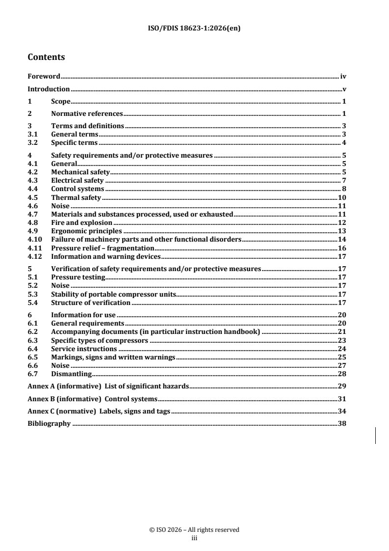
Contents
Foreword . iv
Introduction . v
1 Scope . 1
2 Normative references . 1
3 Terms and definitions . 3
3.1 General terms . 3
3.2 Specific terms . 4
4 Safety requirements and/or protective measures . 5
4.1 General . 5
4.2 Mechanical safety . 5
4.3 Electrical safety . 7
4.4 Control systems . 8
4.5 Thermal safety . 10
4.6 Noise . 11
4.7 Materials and substances processed, used or exhausted . 11
4.8 Fire and explosion . 12
4.9 Ergonomic principles . 13
4.10 Failure of machinery parts and other functional disorders . 14
4.11 Pressure relief – fragmentation . 16
4.12 Information and warning devices . 17
5 Verification of safety requirements and/or protective measures . 17
5.1 Pressure testing . 17
5.2 Noise . 17
5.3 Stability of portable compressor units. 17
5.4 Structure of verification . 17
6 Information for use . 20
6.1 General requirements . 20
6.2 Accompanying documents (in particular instruction handbook) . 21
6.3 Specific types of compressors . 23
6.4 Service instructions . 24
6.5 Markings, signs and written warnings . 25
6.6 Noise . 27
6.7 Dismantling . 28
Annex A (informative) List of significant hazards . 29
Annex B (informative) Control systems . 31
Annex C (normative) Labels, signs and tags . 34
Bibliography . 38
iii
ISO/FDIS 18623-1:2026(en)
Foreword
ISO (the International Organization for Standardization) is a worldwide federation of national standards
bodies (ISO member bodies). The work of preparing International Standards is normally carried out through
ISO technical committees. Each member body interested in a subject for which a technical committee has been
established has the right to be represented on that committee. International organizations, governmental and
non-governmental, in liaison with ISO, also take part in the work. ISO collaborates closely with the
International Electrotechnical Commission (IEC) on all matters of electrotechnical standardization.
The procedures used to develop this document and those intended for its further maintenance are described
in the ISO/IEC Directives, Part 1. In particular, the different approval criteria needed for the different types of
ISO document should be noted. This document was drafted in accordance with the editorial rules of the
ISO/IEC Directives, Part 2 (see www.iso.org/directives).
ISO draws attention to the possibility that the implementation of this document may involve the use of (a)
patent(s). ISO takes no position concerning the evidence, validity or applicability of any claimed patent rights
in respect thereof. As of the date of publication of this document, ISO had not received notice of (a) patent(s)
which may be required to implement this document. However, implementers are cautioned that this may not
represent the latest information, which may be obtained from the patent database available at
www.iso.org/patents. ISO shall not be held responsible for identifying any or all such patent rights.
Any trade name used in this document is information given for the convenience of users and does not
constitute an endorsement.
For an explanation of the voluntary nature of standards, the meaning of ISO specific terms and expressions
related to conformity assessment, as well as information about ISO's adherence to the World Trade
Organization (WTO) principles in the Technical Barriers to Trade (TBT), see www.iso.org/iso/foreword.html.
This document was prepared by Technical Committee ISO/TC 118, Compressors and pneumatic tools,
machines and equipment, Subcommittee SC 6, Air compressors and compressed air systems.
A list of all parts in the ISO 18623 series can be found on the ISO website.
Any feedback or questions on this document should be directed to the user’s national standards body. A
complete listing of these bodies can be found at www.iso.org/members.html.
iv
ISO/FDIS 18623-1:2026(en)
Introduction
This document is a type-C standard as stated in ISO 12100.
This document is of relevance, in particular, for the following stakeholder groups representing the market
players with regard to machinery safety:
— — machine manufacturers (small, medium and large enterprises);
— — health and safety bodies (regulators, accident prevention organisations, market surveillance, etc.)
Others can be affected by the level of machinery safety achieved with the means of the document by the above-
mentioned stakeholder groups:
— — machine users/employers (e.g. small, medium and large enterprises);
— — machine users/employees (e.g. trade unions, organizations for people with special needs);
— — service providers, e. g. for maintenance (small, medium and large enterprises);
— — consumers (in case of machinery intended for use by consumers).
The above-mentioned stakeholder groups have been given the possibility to participate at the drafting process
of this document.
The machinery concerned and the extent to which hazards, hazardous situations or hazardous events are
covered are indicated in the Scope of this document.
When requirements of this type-C standard are different from those which are stated in type-A or type-B
standards, the requirements of this type-C standard take precedence over the requirements of the other
standards for machines that have been designed and built according to the requirements of this type-C
standard.
v
ISO/FDIS 18623-1:2026(en)
Air compressors and compressed air systems — Air compressors —
Part 1: — Safety requirements —
Part 1:
Air compressors
1 Scope
This document is applicable to compressors, partially completed compressor units and compressor units
having an operating pressure greater than 50 kPa and designed to compress air, nitrogen or inert gases. This
document deals with all significant hazards, hazardous situations and events relevant to the design,
installation, operation, maintenance, dismantling and disposal of compressors and compressor units when
they are used as intended and under conditions of misuse which are reasonably foreseeable by the
manufacturer (see Clause 4Clause 4).).
This document includes under the general term compressor units those machines which comprise
— — the compressor,
— — a drive system, and
— — any component or device which is necessary for operation.
This document covers compressors driven by any power media, including battery powered and which are
fitted in or used with motor vehicles.
The significant hazards dealt with in this document are identified in Annex AAnnex A.
This document does not cover requirements for compressors and compressor units used in potentially
explosive atmospheres.
This document is not applicable to compressors and compressor units which are manufactured before the
date of publication of this document.
This document does not cover compressors and compressor units for processing petroleum, petrochemicals,
or chemicals within the scope of ISO/TC 67.
This document does not give performance levels or safety integrity levels for safety related parts of control
systems.
2 Normative references
The following documents are referred to in the text in such a way that some or all of their content constitutes
requirements of this document. For dated references, only the edition cited applies. For undated references,
the latest edition of the referenced document (including any amendments) applies.
ISO 2151, Acoustics — Noise test code for compressors and vacuum pumps — Engineering method (Grade 2)
ISO 3857--1, Compressors, pneumatic tools and machines — Vocabulary — Part 1: General
ISO 3857--2, Compressors, pneumatic tools and machines — Vocabulary — Part 2: Compressors
ISO 4126--1, Safety devices for protection against excessive pressure — Part 1: Safety valves
ISO/FDIS 18623-1:2026(en)
ISO 4413, Hydraulic fluid power — General rules and safety requirements for systems and their components
ISO 4414, Pneumatic fluid power — General rules and safety requirements for systems and their components
ISO 8573--1, Compressed air — Part 1: Contaminants and purity classes
ISO 8573--2, Compressed air — Contaminant measurement — Part 2: Oil aerosol content
ISO 8573--3, Compressed air — Part 3: Test methods for measurement of humidity
ISO 8573--4, Compressed air — Contaminant measurement — Part 4: Particle content
ISO 12100, Safety of machinery — General principles for design — Risk assessment and risk reduction
ISO 13766--1, Earth-moving and building construction machinery — Electromagnetic compatibility (EMC) of
machines with internal electrical power supply — Part 1: General EMC requirements under typical
electromagnetic environmental conditions
ISO 13766--2, Earth-moving and building construction machinery — Electromagnetic compatibility (EMC) of
machines with internal electrical power supply — Part 2: Additional EMC requirements for functional safety
ISO 13849--1, Safety of machinery — Safety-related parts of control systems — Part 1: General principles for
design
ISO 13850, Safety of machinery — Emergency stop function — Principles for design
ISO 13857, Safety of machinery — Safety distances to prevent hazard zones being reached by upper and lower
limbs
ISO 14120, Safety of machinery — Guards — General requirements for the design and construction of fixed and
movable guards
ISO 14122--1, Safety of machinery — Permanent means of access to machinery — Part 1: Choice of fixed means
and general requirements of access
ISO 14122--2, Safety of machinery — Permanent means of access to machinery — Part 2: Working platforms
and walkways
ISO 14122--3, Safety of machinery — Permanent means of access to machinery — Part 3: Stairs, stepladders and
guard-rails
ISO 14122--4, Safety of machinery — Permanent means of access to machinery — Part 4: Fixed ladders
ISO 14123--1, Safety of machinery — Reduction of risks to health resulting from hazardous substances emitted
by machinery — Part 1: Principles and specifications for machinery manufacturers
ISO 15534--1, Ergonomic design for the safety of machinery — Part 1: Principles for determining the dimensions
required for openings for whole-body access into machinery
IEC 60204--1, Safety of machinery -— Electrical equipment of machines -— Part 1: General requirements
IEC 60204--11, Safety of machinery -— Electrical equipment of machines -— Part 11: Requirements for
equipment for voltages above 1 000 V AC or 1 500 V DC and not exceeding 36 kV
IEC 60417-DB--12M, Graphical Symbols For Use On Equipment -— 12-Month Subscription To Online Database
Comprising All Graphical Symbols Published In IEC 60417
ISO/FDIS 18623-1:2026(en)
IEC 61000--6-1, Electromagnetic compatibility (EMC) -— Part 6-1: Generic standards -— Immunity standard
for equipment in residential environments
IEC 61000--6-2, Electromagnetic compatibility (EMC) -— Part 6-2: Generic standards -— Immunity standard
for industrial environments
IEC 61000--6-3, Electromagnetic compatibility (EMC) -— Part 6-3: Generic standards -— Emission standard for
equipment in residential environments
IEC 61000--6-4, Electromagnetic compatibility (EMC) -— Part 6-4: Generic standards -— Emission standard for
industrial environments
IEC 61310--2, Safety of machinery -— Indication, marking and actuation -— Part 2: Requirements for marking
IEC 61310--3, Safety of machinery -— Indication, marking and actuation -— Part 3: Requirements for the
location and operation of actuators
IEC 62061, Safety of machinery -— Functional safety of safety-related control systems
3 Terms and definitions
For the purposes of this document, the terms and definitions given in ISO 12100, ISO 3857-1, ISO 3857--2 and
the following apply.
ISO and IEC maintain terminology databases for use in standardization at the following addresses:
— — ISO Online browsing platform: available at https://www.iso.org/obp
— — IEC Electropedia: available at https://www.electropedia.org/
3.1 General terms
3.1.1 3.1.1
compressor
part of a compressor unit (3.1.3(3.1.3)) that compresses a gas or vapour media to a pressure higher than that
at the inlet
3.1.2 3.1.2
partially completed compressor unit
unit that comprises the compressor (3.1.1(3.1.1),), components and sub-assemblies that is almost a
compressor unit but cannot perform function on its own
3.1.3 3.1.3
compressor unit
unit that comprises the compressor (3.1.1(3.1.1),), a drive system (3.1.4(3.1.4)) and any component or device
which is necessary for operation
3.1.4 3.1.4
drive system
system that consists of a prime mover and coupling mechanism
Note 1 to entry: Prime mover may be an electric motor, steam engine (turbine), etc.
Note 2 to entry: Coupling mechanism may be a drive belt, shaft, gears, etc.
ISO/FDIS 18623-1:2026(en)
3.1.5 3.1.5
inert gas
chemically inactive gas which retains this characteristic even at elevated pressures
3.1.6 3.1.6
pressure
pressure relative to atmospheric pressure, i.e. gauge pressure
Note 1 to entry: In many cases, this is referred to as effective pressure.
Note 2 to entry: The unit kPa for pressure is used 100 kPa = 1 bar.
3.1.7 3.1.7
liquid shock
excessive force resulting from an attempt to compress incompressible media
3.1.8 3.1.8
maximum allowable pressure
maximum pressure for which the compressor (3.1.1(3.1.1)) or compressor unit (3.1.3(3.1.3)) is designed, as
specified by the manufacturer
Note 1 to entry: This is also identified as maximum allowable working pressure.
3.1.9 3.1.9
normal operating conditions
conditions considered to be when the compressor (3.1.1(3.1.1)) is properly maintained and operated within
admissible limits, in particular; ambient temperature, as specified by the manufacturer when compressing the
specified media
3.2 Specific terms
3.2.1 3.2.1
air compressor
compressor (3.1.1(3.1.1)) intended for compression of air, nitrogen or inert gases (3.1.5(3.1.5))
3.2.2 3.2.2
portable compressor unit
compressor unit (3.1.3(3.1.3)) which is wheel-mounted and can be towed on- and off-site
3.2.3 3.2.3
skid-mounted compressor unit
compressor unit (3.1.3(3.1.3)) which is mounted on skids and which can be towed short distances on-site or
transported
3.2.4 3.2.4
gross mass
maximum specified mass of a skid-mounted (3.2.3(3.2.3)) or portable compressor unit (3.2.2(3.2.2)) (including
tools, equipment and fuel)
Note 1 to entry: Tools and equipment include for example concrete breakers, picks and hoses likely to be carried for a
typical working application.
3.2.5 3.2.5
water-injected compressor
compressor (3.1.1(3.1.1)) design in which the compressed media and the water are mixed
ISO/FDIS 18623-1:2026(en)
4 Safety requirements and/or protective measures
4.1 General
The machine shall comply with the following safety requirements and/or protective measures and be verified
in accordance with Clause 5Clause 5. In addition, the machine shall be designed according to the principles of
ISO 12100 for relevant, but not necessarily significant hazards, which are not dealt with by this document.
When choices are necessary for the application of type B standards referred to in this document, i.e. listed in
Clause 2Clause 2,, the manufacturer shall carry out an appropriate risk assessment for making these choices.
The measures adopted to conform with the requirements of this clause shall take account of the state-of-the-
art when more effective technical means become available.
4.2 Mechanical safety
4.2.1 Guards
4.2.1.1 General
When fixed guards have to be removed for periodic maintenance or repair, their fixing systems shall remain
attached to the guard or machinery when the guards are removed.
4.2.1.2 Cutting and severing, friction and abrasion
All moving parts shall be enclosed within the permanent compressor casing or compressor unit cover,
enclosure or canopy. When this is not possible, separate guards shall be provided to prevent contact with all
rotating and reciprocating parts to minimize the risk of cutting and severing, friction and abrasion to
personnel in accordance with ISO 14120 and ISO 13857 for safety distances.
4.2.1.3 Bodily contact
Deflections shall not result in contact with moving parts or permanent deformation of the guard. The
provisions for rigidity of guards shall be in accordance with ISO 14120.
4.2.1.4 Ejection of parts
Moving parts shall be designed and mounted in such a way that in all foreseeable modes of operation the risk
of ejection of parts is minimised. Where the risk assessment identifies a remaining risk of ejection, e.g. a drive
belt from a belt driven compressor, then the impact resistance for guarding shall be in accordance with ISO
14120.
4.2.1.5 Entry to inlet ducts and enclosures
Atmospheric inlets and inspection openings in inlets shall be provided with protective devices, so that persons
cannot be drawn in or danger zones reached when the compressor is running. For this purpose, any openings
shall comply with ISO 13857 for upper and lower limbs, when applicable.
Openings giving access to moving parts creating a risk of trapping or shearing shall be prevented by either
— — total enclosure with an interlocked means of access, e.g. door, cover, etc. such that the compressor is
shut down when the access is opened and cannot be started until the access is closed, or
— — total enclosure without interlock when access to moving parts, e.g. fan belts, barring gear, timing
marks, shall be prevented by local guarding, or
ISO/FDIS 18623-1:2026(en)
— — without total enclosure when access to moving parts, e.g. fan belts, barring gear, timing marks, etc.,
shall be prevented by local guarding.
Where service, maintenance or inspection activities require access within the enclosure doors whilst the
compressor is still operational, consideration shall be given to the additional hazards created and the
measures taken shall be in accordance with ISO 12100. The provisions of 6.3.36.3.3 shall also be applied.
Where whole body access is required to inlet ducts and enclosures for service, maintenance or inspection the
provisions of ISO 15534-1 shall be followed when determining the minimum dimensions of openings for such
whole-body access.
Where whole body access is required to inlet ducts for service, maintenance or inspection, a guard shall be
fitted to prevent unauthorised access. The guard shall be
— — interlocked such that when the guard is opened the compressor is shut-down and cannot be restarted
until the guard is closed, and
— — unintentional closure of the guard is prevented by the use of a trapped key interlock or a padlock
where the only key for the trapped key or the padlock can be retained by the person entering the inlet
duct.
Where it is foreseeable that the compressor remains operational during whole body access to the inlet duct
for service, maintenance or inspection, the design of the inlet duct shall be such that the air flow at the entrance
to the inlet duct shall be ≤2,5 m/s and in addition a protective grid shall be installed inside the duct to prevent
personnel being drawn into the compressor.
A safe system of work shall also be identified in accordance with 6.4.16.4.1.
4.2.2 Fluid injection
The risk of fluid (gas or liquid) injection into the human body shall be minimized by
— — designing and supporting integral pipework, hoses and auxiliaries to withstand vibration, thermal
expansion and their own mass, foreseeable external forces, influence of contaminants and external
chemical substances,
— — ensuring that all piping which is in a position likely to be damaged is protected, robust and sufficiently
supported, but shall be free to move with changing temperature,
— — ensuring that the design of oil/coolant filler plugs does not allow the dangerous release of fluid, e.g. by
means of preventing the removal of the filler plug under pressure or an effective warning system, and
— — the design and location of pressure vents and drains, shall take account of the velocity of air, gas,
vapour or liquid likely to be discharged.
4.2.3 Loss of stability
4.2.3.1 Generally applicable
Compressor units shall be in accordance with ISO 12100.
4.2.3.2 Portable and skid-mounted compressor units
The centre of gravity, mainly associated with the engine/compressor combination shall be low enough to
ensure that the compressor unit remains stable, without tipping or slipping, when used within intended limits.
ISO/FDIS 18623-1:2026(en)
The provisions of 6.3.26.3.2 shall be applied to indicate the intended limits.
Tyres of a portable compressor unit shall be rated to carry the maximum gross mass of the portable
compressor unit at the highest towing speed the compressor unit is intended for. All tyres shall be of the same
construction.
The support leg or jockey wheel shall be capable of supporting the gross nose weightmass of the portable
compressor unit as defined in the instruction handbook. It shall be possible to securely lock it in the support
and towing positions by, for example, a clamping system or removable pin in locating holes.
The jockey wheel device shall be positively retained in the draw bar in the event of the operator leaving it
unlocked.
NOTE Portable compressor units used on-road are also subject to regulations related to motor vehicles and their
trailers.
4.2.4 Slip, trip and fall
If access to elevated areas around a compressor unit is necessary and is an integral part of a compressor unit
then these access areas shall be in accordance with ISO 12100. Where such access is provided, permanent
means of access to working platforms, walkways, fixed ladders and stairways shall be in accordance with ISO
14122-1, ISO 14122-2, ISO 14122-3 and ISO 14122-4.
If access to elevated areas is required and is not an integral part of the compressor unit, appropriate
installation instructions shall be given in the instruction handbook.
4.3 Electrical safety
4.3.1 Generally applicable
The electrical equipment of a compressor unit shall be in accordance with IEC 60204-1 and/ or IEC 60204-
11, or both, as appropriate.
4.3.2 Protection from overload
Where the compressor unit is not fitted with an over-current protection of the power circuit due to it being
installed outside the compressor enclosure on site, the provisions of 6.2.1.3.16.2.1.3.1 shall be followed.
4.3.3 Protection from live parts
Where the compressor unit is not fitted with an electrical disconnecting device, the provisions of
6.2.1.3.26.2.1.3.2 shall be followed.
Electrical and instrument cabling shall
— — be adequately secured and protected,
— — not be in contact with hot surfaces, and
— — have adequate electrical insulation.
Electrical and instrument cabling shall be in accordance with IEC 60204-1.
ISO/FDIS 18623-1:2026(en)
4.3.4 Portable and skid-mounted compressor units
4.3.4.1 General
A suitable over-current protection device, e.g. fuse, shall be provided in the electrical installation to protect
the wiring harness and the electric equipment. This excludes the pre-heat, starting and charging circuits.
Where fuses are provided as over-current protection devices, a type readily available in the country of use
shall be selected, or arrangements made for the supply of spare parts.
4.3.4.2 Batteries
Batteries shall be of the type with lifting handles or with lifting points. They shall be mounted and firmly
secured so there is no risk of electrolyte splashing on personnel and surrounding equipment.
4.4 Control systems
4.4.1 General
Effective control system design shall be in accordance with ISO 12100 and IEC 60204-1. Where software or a
programmable device is used to provide control and safety functions in all its operating modes, it shall comply
with this sectionclause and shall be verified and documented, including updates and revisions. Safety related
parts of control systems can be part of, but not limited to, start, stop, emergency stop, interlocking, high air
temperature, and over-pressure control functions.
Safety systems shall be designed and evaluated using the methods of functional safety as defined in one of the
following standards: ISO 13849-1 or IEC 62061. An introduction to the methods of functional safety is given
in Annex BAnnex B.
The safety related controlled shutdown system and the emergency shutdown system can be initiated by
different safety functions which may require different performance levels (PL) in accordance to ISO 13849-1
or safety integrity levels (SIL) in accordance with IEC 62061.
The safety related controlled shutdown system shall comply with the highest required performance level (PL)
or safety integrity level (SIL) of all the safety functions initiating the safety related controlled shutdown.
The emergency shutdown system shall comply with the highest required performance level (PL) or safety
integrity level (SIL) of all the safety functions initiating the emergency shutdown.
The identification of the required PL and/or SIL is the responsibility of the manufacturer and is outside the
scope of this standard.
The safety related controlled shutdown system and the emergency shutdown system may be combined in one
system.
4.4.2 Failure of safety related control system energy supply
The system design shall be such that failure of the control system energy supply shall not result in a hazardous
situation during the time of the failure or when the control system energy supply is reinstated. In case of failure
of the energy supply of the safety related control system or a part of the safety related control system the
maximum safety performance of the safety related control system shall be carried out.
NOTE Possible energy sources are e.g. electrical energy, hydraulic energy, compressed air, steam, gas.
4.4.3 Start/restart
A protective device to prevent unintended start/restart shall be provided.
ISO/FDIS 18623-1:2026(en)
The requirements for a start and restart shall be in accordance with ISO 13849-1 and, if required, with ISO
12100.
Compressor units that are fitted with automatic or remote start controls shall follow the provisions of
6.2.26.2.2 d) and e).
Where maintenance/service requires the suspension of safety functions and/or protective measures then the
provisions of IEC 60204-1 dealing with the suspension of safety functions and protective measures shall be
followed.
4.4.4 Manual suspension of safety functions
It is not permitted to run the compressor with any automatic shutdown function suspended. If required for
maintenance, the suspension of safety functions shall be in accordance with IEC 60204-1.
4.4.5 Emergency stop function
Where an emergency stop is identified as a requirement in accordance with ISO 12100, the stop category and
colour shall be in accordance with ISO 13850.
Performance level shall also be determined for the emergency stop functions in accordance with ISO 13849-
1.
4.4.6 Safety-related stop function
Compressor units fitted with safety related stop function(s) shall follow the requirements of ISO 13849-1.
Examples of such functions are an interlock fitted to an access door to a packaged compressor unit or a high
air temperature sensor fitted to an oil-injected rotary compressor unit. Emergency stop functions of all types
are covered by 4.4.54.4.5.
4.4.7 Manual reset
A manual reset prior to restart shall be required following a manual emergency stop or an automatic
shutdown.
The requirements for a manual reset after a stop command has been initiated shall be in accordance with ISO
13849-1 and IEC 60204-1.
4.4.8 External influences on electrical equipment
The safety system and other electrical equipment shall be so designed and constructed that they cannot give
rise to a hazardous situation in case of disturbances such as
— — short circuiting,
— — external impacts, e.g. mechanical damage from an external source,
— — interruptions or variations in the supply voltage, and
— — earthing faults.
Failure of the power supply to the control system shall employ an "oriented failure mode system" in
accordance with ISO 12100 having a known failure mode, e.g. bring the machine to a stop.
ISO/FDIS 18623-1:2026(en)
4.4.9 Electromagnetic phenomena
Where applicable, the electrical and electronic equipment of the compressor unit shall comply to the immunity
and emissions provisions of stationary compressors for
— — industrial environments: IEC 61000-6-2 and IEC 61000-6-4,
— — residential, commercial and light industrial environments: IEC 61000-6-1 and IEC 61000-6-3, and
— — skid-mounted and mobile compressor units: ISO 13766-1 and ISO 13766-2,
where such phenomena are identified by risk assessment to be a hazard.
The manufacturer of the compressor unit(s) shall install and wire the equipment and sub-assemblies taking
into account the instructions of the suppliers of these sub-assemblies.
4.4.10 Pneumatic and/or hydraulic control systems
4.4.10.1 General
Where pneumatic and hydraulic equipment forms part of a control system of a compressor unit this shall be
in accordance with ISO 12100 and the following shall apply.
4.4.10.2 Conditioning
Compressed air for measuring, control and safety systems shall be conditioned for the purpose and shall be in
accordance with ISO 4414. Hydraulic systems for measuring, control and safety shall be provided with a filter
system and shall be in accordance with ISO 4413.
Where the level of contamination is critical in pneumatic control systems then those levels shall be identified
by air purity classification system in accordance with ISO 8573-1. Confirmation of the level of aerosol oil
contaminants shall be in accordance with ISO 8573-2, for humidity ISO 8573-3 and for particles ISO 8573-4.
4.4.10.3 Pressure or fluid level drops
A shut down device shall be fitted to stop the compressor unit in case of the hydraulic fluid level or hydraulic
or pneumatic pressure falling below the levels necessary to maintain safe operation. The shutdown device
shall be in accordance with ISO 4414 for pneumatic systems and ISO 4413 for hydraulic systems.
4.5 Thermal safety
External surfaces, subject to extremes of temperature, exposed to personnel during normal operation of the
machine and which may be accidentally touched shall be guarded, e.g. by insulation, where those temperatures
cannot be controlled by design.
For surface temperatures exceeding +70 °C, see ISO 13732-1; for surface temperatures below -−10 °C, see ISO
13732-3.
When guarding is not possible there shall be an adequate warning or a symbol as identified by
C.5ISO 7010:2019-W017 (hot surface) or C.6ISO 7010:2019-W010 (cold surface).
To avoid the risk of hot surfaces due to overheating as a result of a lack of injected oil in the case of starting of
oil injected air compressor units at ambient temperatures below 0 °C, appropriate measures are required to
decrease the oil viscosity before start-up to ensure safe operation. The provisions of 4.10.24.10.2 shall be
applied.
ISO/FDIS 18623-1:2026(en)
In order to avoid 'hot spots' the immersion heaters used for heating the lubricant shall have power dissipation
not greater than 25 kW/m . The heaters used shall be totally immersed in the oil at all times.
To avoid the risk of fire hot piping shall not be in contact with wood or flammable material.
4.6 Noise
Design considerations shall be given to noise reduction, in particular at the source; see ISO/TR 11688-1, ISO
14163, and ISO 15667. Design shall be such that continuous full load operation is possible at the maximum
specified ambient temperature, with all noise attenuating devices and measures in place including all doors
and access covers closed.
NOTE ISO/TR 11688-2 gives useful information on noise generation mechanisms in machinery.
4.7 Materials and substances processed, used or exhausted
4.7.1 Micro-organisms, biological and microbiological substances
4.7.1.1 Condensate
Drainage facilities shall be provided to minimize the accumulation of stagnant liquid, which may promote the
growth of micro-organisms. The drainage systems may be either manual or automatic types and shall allow
for removal of accumulated liquid from piping and accessories such as water jackets, coolers, pulsation
dampers and air receivers. The provisions of 6.2.26.2.2 k), l) and m) shall be applied.
The compressor unit shall be equipped with, for example, drain traps to allow containment of condensate
fluids and subsequent safe draining and disposal.
4.7.1.2 Water-injected compressor units
The choice of materials in the compressor unit should be designed to prevent the growth of bacteria in the
water.
4.7.2 Breathing difficulties
4.7.2.1 Compressor units driven by internal combustion engines
The relationship between the location of the exhaust outlet and the compressor inlet shall be such that in
normal operation the exposure of the compressor inlet to exhaust fumes shall be avoided. In addition to this
requirement the provisions of 6.2.26.2.2 j) and 6.3.26.3.2 e) and f) shall also apply.
4.7.2.2 Nitrogen and inert gases
Where nitrogen or inert gases are processed by a compressor unit leakage can lead to displacement of
breathing air. In all areas accessible to personnel within the compressor unit, the concentration of gases that
can displace breathing air shall be such that the oxygen level is maintained within the limits identified in
national codes or standards. Examples to reduce the build-up of nitrogen or inert gases are:
— — the provision of ventilation in the compressor enclosures;
— — installation of a venting line, to discharge the leakage to a safe area.
Where compressor units of this type are in operation the provisions of 6.2.26.2.2 j) shall be applied.
ISO/FDIS 18623-1:2026(en)
4.8 Fire and explosion
4.8.1 Electrostatic phenomena
In oil flooded rotary compressor units, the air/oil separator and all isolated parts in contact with the
compressed air shall be electrically bonded to the containing vessel.
4.8.2 Oil-flooded rotary air compressor units
To reduce the risk of over-heating and the consequent potential for fire or explosion due to a lack of lubrication
the compressor's lubrication system shall be so designed that a sufficient quantity of lubricant is injected
under all operating conditions, i.e. under normal use as well as under abnormal conditions and operating
modes not covered by safety devices, e.g. faulty starting, emergency stop.
To ensure a sufficient oil supply at least one of the following techniques shall be employed:
— — oil filters in the main circuit shall have a bypass, which is opened by the differential pressure created
across the filter as the filter becomes blocked; the opening pressure to the bypass shall be determined by
the volume of oil required to maintain safe operation;
— — the provision of an alarm and/or shut down device sensing the differential pressure across the oil
filters in the main circuit; the operating pressure to the alarm and/or shut down device shall be
determined by the volume of oil required to maintain safe operation;
— — the provision of an alarm and/or shut down device sensing the oil pressure before entering the
compressor; the alarm and/or shut down shall be activated once the oil pressure falls below the level
required to maintain safe operation.
The design of oil-flooded rotary air compressor units shall be such that the maximum temperature of the
lubricant at any point under normal operating conditions does not exceed the temperature limits of the
compressor lubricant.
The temperature measurement sensor shall be located in the discharge air stream, such that the correct oil/air
mixture temperature measurement is assured.
Oil-flooded rotary air compressor units shall have an automatic shut-down device to switch the compressor
off if the temperature of the compressor oil exceeds the safe limit. The shut-down device shall be actuated at
a temperature not exceeding 120 °C unless lubricants capable of operating at elevated temperatures are used.
When such lubricants are used, the shutdown device shall actuate at a temperature not exceeding 10 °C above
the normal operating design temperature of the compressor but not to exceed the maximum temperature of
the lubricant.
The shutdown system shall meet the requirements of the safety related stop function, see 4.4.64.4.6,, typical
examples are:
— — temperature sensing device acting via an electronic/electrical control or;,
— — temperature indicator/gauge switch.
4.8.3 Oil-lubricated reciprocating air compressor units
The design shall be such that the formation of oil-coke in the outlet of each compression stage is reduced to a
minimum, and provision shall be made for inspecting and cleaning the air cooler. Provisions for inspection
and cleaning may include removable covers or plugs.
ISO/FDIS 18623-1:2026(en)
The following outlet temperatures shall not be exceeded under normal operating conditions when oils rated
for these temperatures are used:
— — 220 °C for single-stage compressors, with a maximum allowable pressure up to 1 000 kPa;
— — 200 °C for single-stage compressors, with a maximum allowable pressure greater than 1 000 kPa,
— — 180 °C for multi-stage compressors with maximum allowable pressure up to 1 000 kPa,
— — 160 °C for multi-stage compressors with maximum allowable pressure greater than 1 000 kPa.
Temperatures higher than those specified above may be permissible when oils rated for higher temperature
applications are used and/or special precautions have been taken to minimize the formation of oil-coke.
Minimizing the formation of coke is achieved by such measures as reducing the oil carry-over into the top of
the cylinder using accurately designed a
...
PROJET
Norme
internationale
ISO/DIS 18623-1.2
ISO/TC 118/SC 6
Compresseurs à air et systèmes à
Secrétariat: SIS
air comprimé — Compresseurs à
Début de vote:
air —
2025-08-12
Partie 1:
Vote clos le:
2025-10-07
Exigences de sécurité des
compresseurs à air
Air compressors and compressed air systems — Air
compressors —
Part 1: Safety requirements
ICS: 23.140
CE DOCUMENT EST UN PROJET DIFFUSÉ
POUR OBSERVATIONS ET APPROBATION. IL
EST DONC SUSCEPTIBLE DE MODIFICATION
ET NE PEUT ÊTRE CITÉ COMME NORME
INTERNATIONALE AVANT SA PUBLICATION EN
TANT QUE TELLE.
OUTRE LE FAIT D’ÊTRE EXAMINÉS POUR
ÉTABLIR S’ILS SONT ACCEPTABLES À DES
FINS INDUSTRIELLES, TECHNOLOGIQUES ET
COMMERCIALES, AINSI QUE DU POINT DE VUE
DES UTILISATEURS, LES PROJETS DE NORMES
INTERNATIONALES DOIVENT PARFOIS ÊTRE
CONSIDÉRÉS DU POINT DE VUE DE LEUR
Ce document n’a pas été rédigé par le Secrétariat central de l’ISO.
POSSIBILITÉ DE DEVENIR DES NORMES
POUVANT SERVIR DE RÉFÉRENCE DANS LA
RÉGLEMENTATION NATIONALE.
LES DESTINATAIRES DU PRÉSENT PROJET
SONT INVITÉS À PRÉSENTER, AVEC LEURS
OBSERVATIONS, NOTIFICATION DES DROITS
DE PROPRIÉTÉ DONT ILS AURAIENT
ÉVENTUELLEMENT CONNAISSANCE
ET À FOURNIR UNE DOCUMENTATION
EXPLICATIVE.
Numéro de référence
ISO/DIS 18623-1.2:2025(fr)
ISO/DIS 18623-1:2025(fr)
ISO TC 118/SC 6/GT 2
ISO/DIS 18623-1.2:2025(fr)
Secrétariat: SIS
Date: 2025-07-29
Compresseurs à air et systèmes à air comprimé — Compresseurs à air — Partie 1: Exigences de
sécurité des compresseurs à air
Air compressors and compressed air systems — Air compressors — Part 1: Air compressor safety
requirements
DOCUMENT PROTÉGÉ PAR COPYRIGHT
© ISO 2025
Tous droits réservés. Sauf prescription différente ou nécessité dans le contexte de sa mise en œuvre, aucune partie de cette
publication ne peut être reproduite ni utilisée sous quelque forme que ce soit et par aucun procédé, électronique ou mécanique,
y compris la photocopie, ou la diffusion sur l’internet ou sur un intranet, sans autorisation écrite préalable. Une autorisation peut
être demandée à l’ISO à l’adresse ci-après ou au comité membre de l’ISO dans le pays du demandeur.
ISO copyright office
Case postale 401 • Ch. de Blandonnet 8
CH-1214 Vernier, Genève
Tél.: +41 22 749 01 11
E-mail: copyright@iso.org
Web: www.iso.org
Publié en Suisse
ii
ISO/DIS 18623-1.2:2025(fr)
Sommaire
Avant-propos . v
Introduction . vi
1 Domaine d'application . 1
2 Références normatives . 1
3 Termes et définitions . 3
3.1 Termes généraux . 3
3.2 Termes spécifiques . 4
4 Exigences de sécurité et/ou mesures de protection . 5
4.1 Généralités . 5
4.2 Sécurité mécanique . 5
4.2.1 Protecteurs . 5
4.2.2 Projection de fluide . 7
4.2.3 Perte de stabilité . 7
4.2.4 Glissade, trébuchement et chute . 7
4.3 Sécurité électrique . 8
4.3.1 Généralement applicable . 8
4.3.2 Protection contre la surcharge . 8
4.3.3 Protection contre les parties actives . 8
4.3.4 Unités de compression mobiles ou montées sur châssis . 8
4.4 Systèmes de commande . 8
4.4.1 Généralités . 8
4.4.2 Défaillance de l'alimentation en énergie du système de commande relatif à la sécurité . 9
4.4.3 Mise en marche/redémarrage . 9
4.4.4 Suspension manuelle des fonctions de sécurité . 9
4.4.5 Fonction d'arrêt d'urgence . 10
4.4.6 Fonction d'arrêt liée à la sécurité . 10
4.4.7 Réarmement manuel . 10
4.4.8 Influences externes sur les équipements électriques . 10
4.4.9 Phénomènes électromagnétiques . 10
4.4.10 Systèmes de commandes pneumatiques et/ou hydrauliques. 11
4.5 Sécurité thermique . 11
4.6 Bruit . 11
4.7 Matériaux et substances traités, utilisés ou dégagés . 12
4.7.1 Micro-organismes, substances biologiques et microbiologiques . 12
4.7.2 Difficultés respiratoires . 12
4.8 Incendie et explosion . 12
4.8.1 Phénomènes électrostatiques. 12
4.8.2 Unités de compression d'air rotatives à injection d'huile . 12
4.8.3 Unités de compression d'air alternatives lubrifiées à l'huile . 13
4.8.4 Unités de compression alternatives lubrifiées à l'huile fonctionnant à plus de 50 bar . 14
4.8.5 Unités de compression entraînées par des moteurs à combustion . 14
4.9 Principes ergonomiques . 14
4.9.1 Généralités . 14
4.9.2 Manutention manuelle des unités de compression . 15
4.9.3 Unités de compression mobiles ou montées sur châssis . 15
4.10 Défaillance des éléments de machine et autres dysfonctionnements . 15
4.10.1 Rupture en cours de fonctionnement . 15
4.10.2 Fonctionnement à basse température . 16
4.10.3 Chocs hydrauliques . 16
4.10.4 Système de refroidissement . 16
iii
ISO/DIS 18623-1.2:2025(fr)
4.11 Décharge de pression — Fragmentation . 17
4.11.1 Généralités. 17
4.11.2 Spécifications pour la conception des dispositifs de décharge de pression . 17
4.11.3 Unités de turbocompression . 17
4.11.4 Unités de compression multi-étagées . 18
4.12 Dispositifs d'information et d'avertissement . 18
5 Vérification des exigences de sécurité et/ou mesures de protection . 18
5.1 Épreuve sous pression . 18
5.2 Bruit . 18
5.2.1 Généralités. 18
5.2.2 Niveau de puissance acoustique des unités de compression destinées à être utilisés en
extérieur . 18
5.3 Stabilité des unités de compression mobiles . 18
5.4 Structure de vérification . 19
6 Informations pour l'utilisation . 21
6.1 Exigences générales . 21
6.2 Documents d'accompagnement (en particulier notice d'instructions) . 22
6.2.1 Manuel d’instructions . 22
6.2.2 Informations relatives à l'utilisation du compresseur/de l'unité de compression . 24
6.3 Types spécifiques de compresseurs . 24
6.3.1 Généralités. 24
6.3.2 Unités de compression d'air mobiles ou montées sur châssis . 25
6.3.3 Ouvertures dans les canalisations d'arrivée d'air et les enveloppes . 25
6.4 Instructions d'entretien . 26
6.4.1 Généralités. 26
6.4.2 Précautions relatives à l'entretien/la maintenance . 26
6.5 Marquages, signaux et avertissements écrits . 27
6.5.1 Généralement applicable . 27
6.5.2 Enveloppes de l’unité de compression . 27
6.5.3 Unités de compression d'air tous terrains mobiles ou montées sur châssis . 27
6.5.4 Marquages (en particulier, plaque signalétique) . 27
6.6 Bruit . 28
6.6.1 Déclaration du niveau de pression acoustique d'émission pondéré A et du niveau de
puissance acoustique pondéré A . 28
6.6.2 Protection de l'ouïe . 28
6.7 Démontage . 29
Annexe A (informative) Liste des phénomènes dangereux significatifs . 30
Annexe B (informative) Systèmes de commande . 32
Annexe C (normative) Étiquettes, signaux et inscriptions . 35
Bibliographie . 40
iv
ISO/DIS 18623-1.2:2025(fr)
Avant-propos
L'ISO (Organisation internationale de normalisation) est une fédération mondiale d'organismes nationaux
de normalisation (comités membres de l'ISO). L'élaboration des Normes internationales est en général
confiée aux comités techniques de l'ISO. Chaque comité membre intéressé par une étude a le droit de faire
partie du comité technique créé à cet effet. Les organisations internationales, gouvernementales et non
gouvernementales, en liaison avec l'ISO participent également aux travaux. L'ISO collabore étroitement
avec la Commission électrotechnique internationale (IEC) en ce qui concerne la normalisation
électrotechnique.
Les procédures utilisées pour élaborer le présent document et celles destinées à sa mise à jour sont décrites
dans les Directives ISO/IEC, Partie 1. Il convient, en particulier de prendre note des différents critères
d'approbation requis pour les différents types de documents ISO. Le présent document a été rédigé
conformément aux règles de rédaction données dans les Directives ISO/IEC, Partie 2
(voir www.iso.org/directives).
L’ISO attire l’attention sur le fait que la mise en application du présent document peut entraîner l’utilisation
d’un ou de plusieurs brevets. L’ISO ne prend pas position quant à la preuve, à la validité et à l’applicabilité
de tout droit de propriété revendiqué à cet égard. À la date de publication du présent document, l’ISO
n'avait pas reçu notification qu’un ou plusieurs brevets pouvaient être nécessaires à sa mise en application.
Toutefois, il y a lieu d’avertir les responsables de la mise en application du présent document que des
informations plus récentes sont susceptibles de figurer dans la base de données de brevets, disponible à
l'adresse www.iso.org/brevets. L’ISO ne saurait être tenue pour responsable de ne pas avoir identifié tout
ou partie de tels droits de propriété.
Les appellations commerciales éventuellement mentionnées dans le présent document sont données pour
information, par souci de commodité, à l’intention des utilisateurs et ne sauraient constituer un
engagement.
Pour une explication de la nature volontaire des normes, la signification des termes et expressions
spécifiques de l'ISO liés à l'évaluation de la conformité, ou pour toute information au sujet de l'adhésion de
l'ISO aux principes de l’Organisation mondiale du commerce (OMC) concernant les obstacles techniques
au commerce (OTC), voir le lien suivant: www.iso.org/iso/fr/avant-propos.html.
Le présent document a été élaboré par le comité technique ISO/TC 118, Compresseurs, machines portatives
pneumatiques, machines et équipements pneumatiques, sous-comité SC 6, Compresseurs à air et systèmes à
air comprimé.
Une liste de toutes les parties de la série ISO 18623 se trouve sur le site de l’ISO.
Il convient que tout retour d’information ou questions sur le présent document soit adressé à l'organisme
national de normalisation de l'utilisateur. Une liste exhaustive desdits organismes se trouve à l’adresse
www.iso.org/members.html.
v
ISO/DIS 18623-1.2:2025(fr)
Introduction
Le présent document est une norme de type C telle que définie dans I’ISO 12100.
Le présent document concerne, en particulier, les groupes de parties prenantes suivants représentant les
acteurs du marché dans le domaine de la sécurité des machines:
— fabricants de machines (petites, moyennes et grandes entreprises);
— organismes de santé et de sécurité (autorités réglementaires, organismes de prévention des risques
professionnels, surveillance du marché, etc.).
D’autres partenaires peuvent être concernés par le niveau de sécurité des machines atteint à l’aide du
document par les groupes de parties prenantes mentionnées ci‐dessus:
— utilisateurs de machines/employeurs (petites, moyennes et grandes entreprises);
— utilisateurs de machines/salariés (par exemple syndicats de salariés, organisations représentant des
personnes ayant des besoins particuliers);
— prestataires de services, par exemple sociétés de maintenance (petites, moyennes et grandes
entreprises).
— consommateurs (dans le cas de machines destinées à être utilisées par des consommateurs).
Les groupes de parties prenantes mentionnés ci‐dessus ont eu la possibilité de participer à l'élaboration
du présent document.
Les machines concernées et l’étendue des phénomènes dangereux, situations dangereuses ou événements
dangereux couverts sont indiqués dans le domaine d’application du présent document.
Lorsque des prescriptions de la présente norme de type C sont différentes de celles énoncées dans des
normes de type A ou de type B, les prescriptions de la présente norme de type C prévalent sur celles des
autres normes, pour les machines ayant été conçues et fabriquées suivant les prescriptions de la présente
norme de type C.
vi
Projet de norme internationale ISO/DIS 18623-1.2:2025(fr)
Compresseurs à air et systèmes à air comprimé —Partie 1:
Exigences de sécurité des compresseurs à air
1 Domaine d'application
Le présent document est applicable aux compresseurs, aux unités de compression incomplètes et aux
unités de compression ayant une pression de service supérieure à 0,5 bar et conçus pour comprimer de
l'air, de l'azote ou des gaz inertes. Le présent document traite tous les phénomènes dangereux, situations
et événements dangereux significatifs pertinents pour la conception, l’installation, le fonctionnement, la
maintenance, le démontage et la mise au rebut des compresseurs et unités de compression, lorsqu’ils sont
utilisés normalement et dans les conditions de mauvais usage raisonnablement prévisibles par le fabricant
(voir Article 4 du présent document).
Le présent document inclue sous le terme général « unités de compression » les machines qui
comprennent:
— le compresseur;
— un système d'entraînement;
— tout composant ou dispositif nécessaire au fonctionnement.
Le présent document couvre les compresseurs entraînés par tout moyen de transmission de puissance, y
compris les compresseurs alimentés par batterie, qui sont intégrés ou utilisés avec des véhicules à moteur.
Les phénomènes dangereux significatifs traités dans le présent document sont identifiés à l’Annexe A.
Le présent document ne couvre pas les exigences relatives aux compresseurs et unités de compression
utilisés dans des atmosphères explosibles.
Le présent document n’est pas applicable aux compresseurs et aux unités de compression fabriqués avant
la date de publication du présent document.
Le présent document ne couvre pas les compresseurs et les unités de compression pour le traitement du
pétrole, des produits pétrochimiques ou des produits chimiques dans le domaine d'application de
l’ISO/TC 67.
Le présent document ne spécifie pas de niveaux de performance ou d’intégrité de sécurité pour les parties
de systèmes de commande relatives à la sécurité.
2 Références normatives
Les documents suivants sont cités dans le texte de sorte qu’ils constituent, pour tout ou partie de leur
contenu, des exigences du présent document. Pour les références datées, seule l'édition citée s'applique.
Pour les références non datées, la dernière édition du document de référence s'applique (y compris les
éventuels amendements).
ISO 2151, Acoustique — Code d'essai acoustique pour les compresseurs et les pompes à vide — Méthode
d'expertise (classe de précision 2)
ISO 3857-1, Compresseurs, outils et machines pneumatiques — Vocabulaire — Partie 1: Généralités
ISO/DIS 18623-1.2:2025(fr)
ISO 3857-2, Compresseurs, outils et machines pneumatiques — Vocabulaire — Partie 2: Compresseurs
ISO 4126-1:2013, Dispositifs de sécurité pour protection contre les pressions excessives — Partie 1: Soupapes
de sûreté
ISO 4126-1:2013/Amd 1:2016, Dispositifs de sécurité pour protection contre les pressions excessives —
Partie 1: Soupapes de sûreté — Amendement 1
ISO 4413, Transmissions hydrauliques — Règles générales et exigences de sécurité relatives aux systèmes et
leurs composants
ISO 4414, Transmissions pneumatiques — Règles générales et exigences de sécurité pour les systèmes et leurs
composants
ISO 8573-1, Air comprimé — Partie 1: Polluants et classes de pureté
ISO 8573-2, Air comprimé — Mesurage de contaminants — Partie 2: Teneur en aérosols d'huile
ISO 8573-3, Air comprimé — Partie 3: Méthodes d'essai pour mesurer le taux d'humidité
ISO 8573-4, Air comprimé — Mesurage des polluants — Partie 4: teneur en particules
ISO 12100, Sécurité des machines — Principes généraux de conception — Appréciation du risque et réduction
du risque
ISO 13766-1, Engins de terrassement et machines pour la construction des bâtiments — Compatibilité
électromagnétique (CEM) des machines équipées de réseaux électriques de distribution interne — Partie 1:
Exigences CEM générales dans des conditions électromagnétiques environnementales typiques
ISO 13766-2, Engins de terrassement et machines pour la construction des bâtiments — Compatibilité
électromagnétique (CEM) des machines équipées de réseaux électriques de distribution interne — Partie 2:
Exigences CEM supplémentaires pour les fonctions de sécurité
ISO 13849-1, Sécurité des machines — Parties des systèmes de commande relatives à la sécurité — Partie 1:
Principes généraux de conception
ISO 13850, Sécurité des machines — Fonction d'arrêt d'urgence — Principes de conception
ISO 13857, Sécurité des machines — Distances de sécurité empêchant les membres supérieurs et inférieurs
d'atteindre les zones dangereuses
ISO 14120, Sécurité des machines — Protecteurs — Prescriptions générales pour la conception et la
construction des protecteurs fixes et mobiles
ISO 14122-1, Sécurité des machines — Moyens d'accès permanents aux machines — Partie 1: Choix d'un
moyen d'accès et des exigences générales d'accès
ISO 14122-2, Sécurité des machines — Moyens d'accès permanents aux machines — Partie 2: Plates-formes
de travail et passerelles
ISO 14122-3, Sécurité des machines — Moyens d'accès permanents aux machines — Partie 3: Escaliers,
échelles à marches et garde-corps
ISO 14122-4, Sécurité des machines — Moyens d'accès permanents aux machines — Partie 4: Échelles fixes
ISO/DIS 18623-1.2:2025(fr)
ISO 14123-1, Sécurité des machines — Réduction des risques pour la santé résultant de substances
dangereuses émises par des machines — Partie 1: Principes et spécifications à l'intention des constructeurs
de machines
ISO 15534-1, Conception ergonomique pour la sécurité des machines — Partie 1: Principes de détermination
des dimensions requises pour les ouvertures destinées au passage de l'ensemble du corps dans les machines
IEC 60204-1, Sécurité des machines — Équipement électrique des machines — Partie 1: Exigences générales
IEC 60204-1:2016/AMD1:2021, Amendement 1 — Sécurité des machines — Équipement électrique des
machines — Partie 1: Exigences générales
IEC 60204-11, Sécurité des machines — Équipement électrique des machines — Partie 11: Exigences pour les
équipements fonctionnant à des tensions supérieures à 1 000 V en courant alternatif ou 1 500 V en courant
continu et ne dépassant pas 36 kV
IEC 60417-DB-12M:2002, Symboles graphiques utilisables sur le matériel — Abonnement de 12 mois à la
base de données en ligne mise à jour régulièrement et comprenant tous les symboles graphiques publiés dans
l'IEC 60417
IEC 61000-6-2, Compatibilité électromagnétique (CEM) — Partie 6-2: Normes génériques — Immunité pour
les environnements industriels
IEC 61000-6-4, Compatibilité électromagnétique (CEM) — Partie 6-4: Normes génériques — Norme sur
l'émission pour les environnements industriels
IEC 61310-2:2007, Sécurité des machines — Indication, marquage et manœuvre — Partie 2: Exigences pour
le marquage
IEC 62061, Sécurité des machines — Sécurité fonctionnelle des systèmes de commande relatifs à la sécurité
3 Termes et définitions
Pour les besoins du présent document, les termes et définitions donnés dans l’ISO 12100, l’ISO 3857-1,
l’ISO 3857-2 ainsi que les suivants s'appliquent.
L’ISO et l’IEC tiennent à jour des bases de données terminologiques destinées à être utilisées en
normalisation, consultables aux adresses suivantes:
— ISO Online browsing platform: disponible à l’adresse https://www.iso.org/obp
— IEC Electropedia: disponible à l’adresse https://www.electropedia.org/
3.1 Termes généraux
3.1.1
compresseur
partie d'une unité de compression (3.1.3) qui comprime un gaz ou la vapeur à une pression supérieure à la
pression d'aspiration
3.1.2
unité de compression incomplète
unité qui comprend le compresseur (3.1.1), des composants et des sous-ensembles, qui est presque une
unité de compression, mais qui ne peut pas fonctionner seule
ISO/DIS 18623-1.2:2025(fr)
3.1.3
unité de compression
unité qui comprend le compresseur (3.1.1), un système d'entraînement (3.1.4) et tout composant ou
dispositif nécessaire au fonctionnement
3.1.4
système d'entraînement
système qui consiste en une machine motrice et un mécanisme d'accouplement
Note 1 à l'article: La machine motrice peut être un moteur électrique, un moteur à vapeur (turbine), etc.
Note 2 à l'article: Le mécanisme d'accouplement peut être une courroie d'entraînement, un arbre, des engrenages,
etc.
3.1.5
gaz inerte
gaz inactif chimiquement qui conserve cette caractéristique même à des pressions élevées
3.1.6
pression
pression par rapport à la pression atmosphérique, c'est-à-dire pression manométrique
Note 1 à l'article: Dans bien des cas, elle est appelée pression effective.
Note 2 à l'article: L'unité utilisée pour la pression est le bar. 1 bar = 100 kPa.
3.1.7
choc hydraulique
force excessive résultant d'une tentative de compression de fluides incompressibles
3.1.8
pression maximale admissible
pression maximale pour laquelle le compresseur (3.1.1) ou l’unité de compression (3.1.3) est conçu(e), telle
que spécifiée par le fabricant
Note 1 à l'article: Elle est également identifiée en tant que pression de service maximale admissible.
3.1.9
conditions normales de fonctionnement
conditions auxquelles le compresseur (3.1.1) est correctement entretenu et exploité dans les limites
admissibles, notamment de température ambiante, telles que spécifiées par le fabricant pour comprimer
les fluides spécifiés
3.2 Termes spécifiques
3.2.1
compresseur d'air
compresseur (3.1.1) conçu pour comprimer de l'air, de l'azote ou des gaz inertes (3.1.5)
3.2.2
compresseurs mobiles ou montés sur châssis
3.2.2.1
unité de compression mobile
unité de compression (3.1.3) montée sur roues et pouvant être remorquée sur le site et en dehors du site
ISO/DIS 18623-1.2:2025(fr)
3.2.2.2
unité de compression montée sur châssis
unité de compression (3.1.3) qui est montée sur châssis et qui peut être remorquée sur de courtes distances
sur le site ou transportée
3.2.2.3
masse brute
masse maximale spécifiée de l’unité de compression montée sur châssis ou mobile (3.2.2.1) (incluant les
outils, les équipements et le carburant)
Note 1 à l'article: Les outils et les équipements comprennent, par exemple, les brises-béton, les marteaux-piqueurs et
les tuyaux devant être transportés pour une application de travail type.
3.2.3
compresseur à injection d'eau
compresseur (3.1.1) conçu de telle sorte que le fluide comprimé et l'eau se mélangent
4 Exigences de sécurité et/ou mesures de protection
4.1 Généralités
La machine doit être conforme aux exigences de sécurité et/ou mesures de protection suivantes et être
contrôlée conformément à l'Article 5. De plus, les machines doivent être conçues selon les principes de
l’ISO 12100 pour les phénomènes dangereux pertinents, mais pas nécessairement significatifs, qui ne sont
pas traités dans le présent document.
Lorsque des choix sont nécessaires pour l’application des normes de type B mentionnées dans le présent
document, c’est-à-dire listées à l’Article 2, le fabricant doit réaliser une évaluation des risques appropriée
pour faire ces choix.
Les mesures adoptées pour se conformer aux exigences du présent article doivent tenir compte de l'état
de la technique lorsque des moyens techniques plus efficaces deviennent disponibles.
4.2 Sécurité mécanique
4.2.1 Protecteurs
4.2.1.1 Généralités
Lorsque des protecteurs fixes doivent être déposés en vue de la maintenance périodique ou d'une
réparation, leurs systèmes de fixation doivent rester solidaires du protecteur ou de la machine lorsque les
protecteurs sont retirés.
4.2.1.2 Coupure et sectionnement, frottement et abrasion
Toutes les pièces mobiles doivent être enfermées à l'intérieur du carter permanent du compresseur ou du
couvercle, de l'enveloppe ou de l'abri permanent de l’unité de compression. En cas d’impossibilité, des
protecteurs distincts doivent être prévus pour empêcher un contact avec toutes les pièces tournantes et à
mouvement alternatif, afin de réduire au minimum les risques de coupure, de sectionnement, de
frottement et d’abrasion pour le personnel conformément à l’ISO 14120 et l’ISO 13857 pour les distances
de sécurité.
ISO/DIS 18623-1.2:2025(fr)
4.2.1.3 Contact corporel
Les flexions ne doivent pas aboutir à un contact avec des pièces mobiles, ni entraîner une déformation
permanente du protecteur. Les dispositions relatives à la rigidité des protecteurs doivent être conformes
à l’ISO 14120.
4.2.1.4 Éjection de pièces
Les pièces mobiles doivent être conçues et montées de manière à réduire au minimum le risque d'éjection
de pièces pour tous les modes de fonctionnement prévisibles. Lorsque l’évaluation des risques identifie un
risque résiduel d’éjection, par exemple d’une courroie d’entraînement d’un compresseur entraîné par
courroie, alors la résistance au choc des protecteurs doit être conforme à l’ISO 14120.
4.2.1.5 Ouvertures dans les canalisations d'arrivée d'air et les enveloppes
Les entrées d'air et ouvertures d'inspection sur l'aspiration doivent être équipées de dispositifs de
protection afin que les personnes ne puissent pas y être aspirées ou que les zones dangereuses ne puissent
pas être atteintes lorsque le compresseur fonctionne. À cette fin, toute ouverture doit être conforme à
l’ISO 13857 pour les membres supérieurs et inférieurs, le cas échéant.
Les ouvertures donnant accès aux pièces mobiles présentant un risque d’emprisonnement ou de
cisaillement doivent être protégées par:
— une enveloppe intégrale avec un moyen d'accès muni d'un dispositif de verrouillage, par exemple une
porte, un couvercle, etc., tel que le compresseur soit arrêté lorsque l’accès est ouvert et qu’il ne puisse
pas démarrer tant que l'accès n'est pas fermé; ou
— une enveloppe intégrale sans dispositif de verrouillage lorsque l’accès aux pièces mobiles, par exemple
courroies de ventilateur, vireur, repères de calage, etc., doit être empêché par un dispositif local de
protection; ou
— sans enveloppe intégrale lorsque l'accès aux pièces mobiles, par exemple courroies de ventilateur,
vireur, repères de calage, etc., doit être empêché par un dispositif local de protection.
Lorsque les activités d’entretien, de maintenance ou d’inspection requièrent de franchir les portes de
l’enveloppe alors que le compresseur fonctionne encore, les phénomènes dangereux supplémentaires
engendrés doivent être pris en compte et les mesures prises doivent être conformes à l’ISO 12100. Les
dispositions du 6.3.3 s'appliquent également.
Lorsqu’il est requis de faire passer l'ensemble du corps dans des canalisations d’arrivée d’air et des
enveloppes pour l’entretien, la maintenance ou l’inspection, les dispositions de l’ISO 15534-1 doivent être
respectées lors de la détermination des dimensions minimales des ouvertures destinées au passage de
l’ensemble du corps.
Lorsqu’il est requis de faire passer l'ensemble du corps dans des canalisations d'arrivée d'air pour
l'entretien, la maintenance ou l'inspection, un protecteur doit être installé pour empêcher tout accès non
autorisé. Le protecteur doit être:
— verrouillé de telle sorte que, lorsque le protecteur est ouvert, le compresseur soit arrêté et ne puisse
pas redémarrer tant que le protecteur n'est pas fermé; et
— toute fermeture accidentelle du protecteur soit empêchée par l’utilisation d’un dispositif de
verrouillage avec serrure à pêne ou d’un cadenas, la seule clé adaptée à la serrure à pêne ou au cadenas
peut être conservée par la personne pénétrant dans la canalisation.
Lorsqu’il est prévisible que le compresseur continue de fonctionner pendant le passage de l’ensemble du
corps dans la canalisation d’arrivée d’air à des fins d’entretien, de maintenance ou d’inspection, la
conception de la canalisation d’arrivée d’air doit être telle que le débit d’air à l’entrée de la canalisation
ISO/DIS 18623-1.2:2025(fr)
d’arrivée d’air soit ≤ 2,5 m/s et, de plus, une grille de protection doit être installée à l'intérieur de la
canalisation pour empêcher le personnel d'être entraîné dans le compresseur.
Un système de travail sûr doit également être identifié conformément au 6.4.1.
4.2.2 Projection de fluide
Le risque de projection de fluide (gaz ou liquide) sur le corps humain doit être réduit à un minimum en
respectant les points suivants:
— concevoir et soutenir les tuyauteries, flexibles et auxiliaires solidaires de telle sorte qu'elles puissent
résister aux vibrations, à la dilatation thermique et à leur propre masse, aux forces extérieures
prévisibles, à l'influence de polluants et de substances chimiques externes;
— s'assurer que toute la tuyauterie, qui est dans une position susceptible d'être exposée à des
détériorations, est protégée, robuste et suffisamment soutenue, tout en pouvant bouger librement
sous l'effet d'un changement de température;
— s'assurer que, par conception, les bouchons de remplissage d'huile/de fluide de refroidissement ne
permettent pas la libération dangereuse de fluide, par exemple en empêchant le retrait du bouchon de
remplissage sous pression ou au moyen d'un système d'avertissement efficace;
— la conception et l'emplacement des dispositifs de décharge de pression et des dispositifs de drainage
doivent tenir compte de la vitesse de l'air, du gaz, de la vapeur ou du liquide susceptible d'être expulsés.
4.2.3 Perte de stabilité
4.2.3.1 Généralement applicable
Les unités de compression doivent être conformes à l'ISO 12100.
4.2.3.2 Unités de compression mobiles ou montées sur châssis
Le centre de gravité, généralement associé à la combinaison moteur/compresseur, doit être suffisamment
bas pour garantir que l'unité de compression, utilisé dans les limites prévues, reste stable sans basculer, ni
glisser.
Les dispositions du 6.3.2 doivent être appliquées pour indiquer les limites prévues.
Les pneus d’une unité de compression mobile doivent être calculés de façon à pouvoir supporter la masse
brute maximale de l’unité de compression mobile à la vitesse maximale de remorquage pour laquelle
l'unité de compression est prévue. Tous les pneus doivent être de même conception.
Le pied de support ou la roue jockey doit être en mesure de supporter le poids brut du nez de l’unité de
compression mobile, tel que défini dans la notice d'instructions. Il doit être possible de le (la) verrouiller
dans les positions d'appui et de remorquage, par exemple au moyen d'un système de serrage ou d'une
broche amovible insérée dans des trous de positionnement.
Le système avec roue jockey doit être retenu positivement dans la barre de remorquage, au cas où
l'opérateur le laisserait déverrouillé.
NOTE Les unités de compression mobiles utilisées sur route sont également soumises aux réglementations
relatives aux véhicules à moteur et à leurs remorques.
4.2.4 Glissade, trébuchement et chute
Si l’accès aux zones surélevées en périphérie d’une unité de compression est nécessaire et fait partie
intégrante de l’unité de compression, alors ces zones d’accès doivent être conformes à l’ISO 12100.
Lorsqu’un tel accès est prévu, les moyens d’accès permanents aux plates-formes de travail, passerelles,
ISO/DIS 18623-1.2:2025(fr)
échelles fixes et escaliers doivent être conformes à l’ISO 14122-1, l’ISO 14122-2,
l’ISO 14122-3 et l’ISO 14122-4.
Si l’accès aux zones surélevées est requis et ne fait pas partie intégrante de l’unité de compression, des
instructions d'installation appropriées doivent être données dans la notice d'instructions.
4.3 Sécurité électrique
4.3.1 Généralement applicable
L’équipement électrique d’une unité de compression doit être conforme à l’IEC 60204-1 et/ou l’IEC 60204-
11, selon le cas.
4.3.2 Protection contre la surcharge
Lorsque l’unité de compression n’est pas équipée d’une protection contre les surintensités du circuit de
puissance du fait que ce circuit est installé à l’extérieur de l’enveloppe du compresseur sur le site, les
dispositions du 6.2.1.3.1 doivent être respectées.
4.3.3 Protection contre les parties actives
Lorsque l’unité de compression n’est pas équipée d’un dispositif de sectionnement de l’alimentation
électrique, les dispositions du 6.2.1.3.2 doivent être respectées.
Le câblage électrique et le câblage des instruments:
— doivent être correctement fixés et protégés;
— ne doivent pas être au contact de surfaces chaudes;
— doivent posséder une isolation électrique adéquate.
Le câblage électrique et le câblage des instruments doivent être conformes à l’IEC 60204-1.
4.3.4 Unités de compression mobiles ou montées sur châssis
4.3.4.1 Généralités
Un dispositif de protection approprié contre les surintensités, par exemple un fusible, doit être fourni dans
l’installation électrique pour protéger le faisceau de fils et l’équipement électrique. Cela exclut les circuits
de préchauffage, du démarreur et de charge des batteries. Lorsque des fusibles sont fournis comme
dispositifs de protection contre les surintensités, il faut choisir un type de fusible facilement disponible
dans le pays d'utilisation ou il faut prendre des dispositions pour l'approvisionnement en pièces de
rechange.
4.3.4.2 Batteries
Les batteries doivent être munies de poignées ou de points de levage. Elles doivent être montées et
solidement fixées de façon à ne faire courir aux personnes et aux équipements situés à proximité aucun
risque d'être éclaboussés par de l'électrolyte.
4.4 Systèmes de commande
4.4.1 Généralités
Une conception efficace des systèmes de commande doit être conforme à l’ISO 12100
et l’IEC 60204-1. Lorsqu’un logiciel ou un dispositif programmable est utilisé pour assurer des fonctions
de commande et de sécurité dans tous ses modes de fonctionnement, il doit être conforme à la présente
ISO/DIS 18623-1.2:2025(fr)
section et doit être vérifié et documenté, y compris les mises à jour et les révisions. Les parties des systèmes
de commande relatives à la sécurité peuvent faire partie, sans toutefois s’y limiter, des fonctions de mise
en marche, d'arrêt, d'arrêt d'urgence, de verrouillage, de contrôle de la température élevée de l'air et de la
surpression.
Les systèmes de sécurité doivent être conçus et évalués à l’aide des méthodes de sécurité fonctionnelle
telles que définies dans l’une des normes suivantes: ISO 13849-1 ou IEC 62061. Une introduction aux
méthodes de sécurité fonctionnelle est donnée dans l’Annexe B.
Le système d'arrêt commandé relatif à la sécurité et le système d'arrêt d'urgence peuvent être déclenchés
par différentes fonctions de sécurité, qui peuvent nécessiter différents niveaux de performance (PL)
conformément à l'ISO 13849-1 ou différents niveaux d'intégrité de sécurité (SIL) conformément à
l'IEC 62061.
Le système d'arrêt commandé relatif à la sécurité doit être conforme au plus haut niveau de performance
(PL) ou niveau d'intégrité de sécurité (SIL) requis de toutes les fonctions de sécurité qui déclenchent l'arrêt
commandé relatif à la sécurité.
Le système d'arrêt d'urgence doit être conforme au plus haut niveau de performance (PL) ou niveau
d'intégrité de sécurité (SIL
...
PROJET FINAL
Norme
internationale
ISO/FDIS 18623-1
ISO/TC 118/SC 6
Compresseurs à air et systèmes à
Secrétariat: SIS
air comprimé — Sécurité —
Début de vote:
2026-05-05
Partie 1:
Compresseurs à air
Vote clos le:
2026-06-30
Air compressors and compressed air systems — Safety —
Part 1: Air compressors
LES DESTINATAIRES DU PRÉSENT PROJET SONT
INVITÉS À PRÉSENTER, AVEC LEURS OBSERVATIONS,
NOTIFICATION DES DROITS DE PROPRIÉTÉ DONT ILS
AURAIENT ÉVENTUELLEMENT CONNAISSANCE ET À
FOURNIR UNE DOCUMENTATION EXPLICATIVE.
OUTRE LE FAIT D’ÊTRE EXAMINÉS POUR
ÉTABLIR S’ILS SONT ACCEPTABLES À DES FINS
INDUSTRIELLES, TECHNOLOGIQUES ET COM-MERCIALES,
AINSI QUE DU POINT DE VUE DES UTILISATEURS, LES
PROJETS DE NORMES
INTERNATIONALES DOIVENT PARFOIS ÊTRE CONSIDÉRÉS
DU POINT DE VUE DE LEUR POSSI BILITÉ DE DEVENIR DES
NORMES POUVANT
SERVIR DE RÉFÉRENCE DANS LA RÉGLEMENTATION
NATIONALE.
Numéro de référence
ISO/FDIS 18623-1:2026(fr) © ISO 2026
PROJET FINAL
ISO/FDIS 18623-1:2026(fr)
Norme
internationale
ISO/FDIS 18623-1
ISO/TC 118/SC 6
Compresseurs à air et systèmes à
Secrétariat: SIS
air comprimé — Sécurité —
Début de vote:
Partie 1: 2026-05-05
Compresseurs à air
Vote clos le:
2026-06-30
Air compressors and compressed air systems — Safety —
Part 1: Air compressors
LES DESTINATAIRES DU PRÉSENT PROJET SONT
INVITÉS À PRÉSENTER, AVEC LEURS OBSERVATIONS,
NOTIFICATION DES DROITS DE PROPRIÉTÉ DONT ILS
AURAIENT ÉVENTUELLEMENT CONNAISSANCE ET À
FOURNIR UNE DOCUMENTATION EXPLICATIVE.
DOCUMENT PROTÉGÉ PAR COPYRIGHT
OUTRE LE FAIT D’ÊTRE EXAMINÉS POUR
ÉTABLIR S’ILS SONT ACCEPTABLES À DES FINS
© ISO 2026 INDUSTRIELLES, TECHNOLOGIQUES ET COM-MERCIALES,
AINSI QUE DU POINT DE VUE DES UTILISATEURS, LES
Tous droits réservés. Sauf prescription différente ou nécessité dans le contexte de sa mise en œuvre, aucune partie de cette
PROJETS DE NORMES
INTERNATIONALES DOIVENT PARFOIS ÊTRE CONSIDÉRÉS
publication ne peut être reproduite ni utilisée sous quelque forme que ce soit et par aucun procédé, électronique ou mécanique,
DU POINT DE VUE DE LEUR POSSI BILITÉ DE DEVENIR DES
y compris la photocopie, ou la diffusion sur l’internet ou sur un intranet, sans autorisation écrite préalable. Une autorisation peut
NORMES POUVANT
être demandée à l’ISO à l’adresse ci-après ou au comité membre de l’ISO dans le pays du demandeur.
SERVIR DE RÉFÉRENCE DANS LA RÉGLEMENTATION
NATIONALE.
ISO copyright office
Case postale 401 • Ch. de Blandonnet 8
CH-1214 Vernier, Genève
Tél.: +41 22 749 01 11
E-mail: copyright@iso.org
Web: www.iso.org
Publié en Suisse Numéro de référence
ISO/FDIS 18623-1:2026(fr) © ISO 2026
ii
ISO/FDIS 18623-1:2026(fr)
Sommaire Page
Avant-propos .v
Introduction .vi
1 Domaine d'application . 1
2 Références normatives . 1
3 Termes et définitions . 3
3.1 Termes généraux .3
3.2 Termes spécifiques .4
4 Exigences de sécurité et/ou mesures de protection . 4
4.1 Généralités .4
4.2 Sécurité mécanique .5
4.2.1 Protecteurs .5
4.2.2 Projection de fluide .6
4.2.3 Perte de stabilité .6
4.2.4 Glissade, trébuchement et chute .7
4.3 Sécurité électrique .7
4.3.1 Généralement applicable .7
4.3.2 Protection contre la surcharge .7
4.3.3 Protection contre les parties actives .7
4.3.4 Unités de compression mobiles ou montées sur châssis .8
4.4 Systèmes de commande.8
4.4.1 Généralités .8
4.4.2 Défaillance de l'alimentation en énergie du système de commande relatif à la
sécurité .8
4.4.3 Mise en marche/redémarrage .9
4.4.4 Suspension manuelle des fonctions de sécurité .9
4.4.5 Fonction d'arrêt d'urgence .9
4.4.6 Fonction d'arrêt liée à la sécurité .9
4.4.7 Réarmement manuel .9
4.4.8 Influences externes sur les équipements électriques .9
4.4.9 Phénomènes électromagnétiques .10
4.4.10 Systèmes de commandes pneumatiques et/ou hydrauliques .10
4.5 Sécurité thermique .10
4.6 Bruit .11
4.7 Matériaux et substances traités, utilisés ou dégagés .11
4.7.1 Micro-organismes, substances biologiques et microbiologiques .11
4.7.2 Difficultés respiratoires . .11
4.8 Incendie et explosion . 12
4.8.1 Phénomènes électrostatiques . 12
4.8.2 Unités de compression d'air rotatives à injection d'huile . 12
4.8.3 Unités de compression d'air alternatives lubrifiées à l'huile . 12
4.8.4 Unités de compression alternatives lubrifiées à l'huile fonctionnant à plus de
5 000 kPa . 13
4.8.5 Unités de compression entraînées par des moteurs à combustion . 13
4.9 Principes ergonomiques. 13
4.9.1 Généralités . 13
4.9.2 Manutention manuelle des unités de compression .14
4.9.3 Unités de compression mobiles ou montées sur châssis .14
4.10 Défaillance des éléments de machine et autres dysfonctionnements .14
4.10.1 Rupture en cours de fonctionnement .14
4.10.2 Fonctionnement à basse température. 15
4.10.3 Chocs hydrauliques . 15
4.10.4 Système de refroidissement .16
4.11 Décharge de pression — Fragmentation .16
4.11.1 Généralités .16
iii
ISO/FDIS 18623-1:2026(fr)
4.11.2 Spécifications pour la conception des dispositifs de décharge de pression .16
4.11.3 Unités de turbocompression .17
4.11.4 Unités de compression multi-étagées .17
4.12 Dispositifs d'information et d'avertissement .17
5 Vérification des exigences de sécurité et/ou mesures de protection . 17
5.1 Épreuve sous pression .17
5.2 Bruit .17
5.2.1 Généralités .17
5.2.2 Niveau de puissance acoustique des unités de compression destinées à être
utilisés en extérieur .17
5.3 Stabilité des unités de compression mobiles .18
5.4 Structure de vérification .18
6 Informations pour l'utilisation .20
6.1 Exigences générales . 20
6.2 Documents d'accompagnement (en particulier notice d'instructions) . 20
6.2.1 Manuel d’instructions . 20
6.2.2 Informations relatives à l'utilisation du compresseur/de l'unité de compression . 22
6.3 Types spécifiques de compresseurs . 23
6.3.1 Généralités . 23
6.3.2 Unités de compression d'air mobiles ou montées sur châssis . 23
6.3.3 Ouvertures dans les canalisations d'arrivée d'air et les enveloppes .24
6.4 Instructions d'entretien .24
6.4.1 Généralités .24
6.4.2 Précautions relatives à l'entretien/la maintenance. 25
6.5 Marquages, signaux et avertissements écrits . 25
6.5.1 Généralement applicable . 25
6.5.2 Enveloppes de l’unité de compression . 26
6.5.3 Unités de compression d'air tous terrains mobiles ou montées sur châssis . 26
6.5.4 Marquages (en particulier, plaque signalétique) . 26
6.6 Bruit .27
6.6.1 Déclaration du niveau de pression acoustique d'émission pondéré A et du niveau
de puissance acoustique pondéré A .27
6.6.2 Protection de l'ouïe .27
6.7 Démontage .27
Annexe A (informative) Liste des phénomènes dangereux significatifs.28
Annexe B (informative) Systèmes de commande .30
Annexe C (normative) Étiquettes, signaux et inscriptions .32
Bibliographie .35
iv
ISO/FDIS 18623-1:2026(fr)
Avant-propos
L'ISO (Organisation internationale de normalisation) est une fédération mondiale d'organismes nationaux
de normalisation (comités membres de l'ISO). L'élaboration des Normes internationales est en général
confiée aux comités techniques de l'ISO. Chaque comité membre intéressé par une étude a le droit de faire
partie du comité technique créé à cet effet. Les organisations internationales, gouvernementales et non
gouvernementales, en liaison avec l'ISO participent également aux travaux. L'ISO collabore étroitement avec
la Commission électrotechnique internationale (IEC) en ce qui concerne la normalisation électrotechnique.
Les procédures utilisées pour élaborer le présent document et celles destinées à sa mise à jour sont
décrites dans les Directives ISO/IEC, Partie 1. Il convient, en particulier, de prendre note des différents
critères d'approbation requis pour les différents types de documents ISO. Le présent document
a été rédigé conformément aux règles de rédaction données dans les Directives ISO/IEC, Partie 2
(voir www.iso.org/directives).
L’ISO attire l’attention sur le fait que la mise en application du présent document peut entraîner l’utilisation
d’un ou de plusieurs brevets. L’ISO ne prend pas position quant à la preuve, à la validité et à l’applicabilité de
tout droit de propriété revendiqué à cet égard. À la date de publication du présent document, l’ISO n'avait pas
reçu notification qu’un ou plusieurs brevets pouvaient être nécessaires à sa mise en application. Toutefois,
il y a lieu d’avertir les responsables de la mise en application du présent document que des informations
plus récentes sont susceptibles de figurer dans la base de données de brevets, disponible à l'adresse
www.iso.org/brevets. L’ISO ne saurait être tenue pour responsable de ne pas avoir identifié tout ou partie de
tels droits de propriété.
Les appellations commerciales éventuellement mentionnées dans le présent document sont données pour
information, par souci de commodité, à l’intention des utilisateurs et ne sauraient constituer un engagement.
Pour une explication de la nature volontaire des normes, la signification des termes et expressions
spécifiques de l'ISO liés à l'évaluation de la conformité, ou pour toute information au sujet de l'adhésion de
l'ISO aux principes de l’Organisation mondiale du commerce (OMC) concernant les obstacles techniques au
commerce (OTC), voir le lien suivant: www.iso.org/iso/fr/avant-propos.html.
Le présent document a été élaboré par le comité technique ISO/TC 118, Compresseurs, machines portatives
pneumatiques, machines et équipements pneumatiques, sous-comité SC 6, Compresseurs à air et systèmes à air
comprimé.
Une liste de toutes les parties de la série ISO 18623 se trouve sur le site de l’ISO.
Il convient que tout retour d’information ou questions sur le présent document soit adressé à l'organisme
national de normalisation de l'utilisateur. Une liste exhaustive desdits organismes se trouve à l’adresse
www.iso.org/members.html.
v
ISO/FDIS 18623-1:2026(fr)
Introduction
Le présent document est une norme de type C telle que définie dans I’ISO 12100.
Le présent document concerne, en particulier, les groupes de parties prenantes suivants représentant les
acteurs du marché dans le domaine de la sécurité des machines:
— fabricants de machines (petites, moyennes et grandes entreprises);
— organismes de santé et de sécurité (autorités réglementaires, organismes de prévention des risques
professionnels, surveillance du marché, etc.).
D’autres partenaires peuvent être concernés par le niveau de sécurité des machines atteint à l’aide du
document par les groupes de parties prenantes mentionnées ci-dessus:
— utilisateurs de machines/employeurs (par exemple, petites, moyennes et grandes entreprises);
— utilisateurs de machines/salariés (par exemple, syndicats de salariés, organisations représentant des
personnes ayant des besoins particuliers);
— prestataires de services, par exemple sociétés de maintenance (petites, moyennes et grandes entreprises).
— consommateurs (dans le cas de machines destinées à être utilisées par des consommateurs).
Les groupes de parties prenantes mentionnés ci-dessus ont eu la possibilité de participer à l'élaboration du
présent document.
Les machines concernées et l’étendue des phénomènes dangereux, situations dangereuses ou événements
dangereux couverts sont indiqués dans le domaine d’application du présent document.
Lorsque des prescriptions de la présente norme de type C sont différentes de celles énoncées dans des
normes de type A ou de type B, les prescriptions de la présente norme de type C prévalent sur celles des
autres normes, pour les machines ayant été conçues et fabriquées suivant les prescriptions de la présente
norme de type C.
vi
PROJET FINAL Norme internationale ISO/FDIS 18623-1:2026(fr)
Compresseurs à air et systèmes à air comprimé — Sécurité —
Partie 1:
Compresseurs à air
1 Domaine d'application
Le présent document est applicable aux compresseurs, aux unités de compression incomplètes et aux
unités de compression ayant une pression de service supérieure à 50 kPa et conçus pour comprimer de
l'air, de l'azote ou des gaz inertes. Le présent document traite tous les phénomènes dangereux, situations
et événements dangereux significatifs pertinents pour la conception, l’installation, le fonctionnement, la
maintenance, le démontage et la mise au rebut des compresseurs et unités de compression, lorsqu’ils sont
utilisés normalement et dans les conditions de mauvais usage raisonnablement prévisibles par le fabricant
(voir Article 4).
Le présent document inclue sous le terme général «unités de compression» les machines qui comprennent:
— le compresseur;
— un système d'entraînement; et
— tout composant ou dispositif nécessaire au fonctionnement.
Le présent document couvre les compresseurs entraînés par tout moyen de transmission de puissance, y
compris les compresseurs alimentés par batterie, qui sont intégrés ou utilisés avec des véhicules à moteur.
Les phénomènes dangereux significatifs traités dans le présent document sont identifiés à l’Annexe A.
Le présent document ne couvre pas les exigences relatives aux compresseurs et unités de compression
utilisés dans des atmosphères explosibles.
Le présent document n’est pas applicable aux compresseurs et aux unités de compression fabriqués avant la
date de publication du présent document.
Le présent document ne couvre pas les compresseurs et les unités de compression pour le traitement du
pétrole, des produits pétrochimiques ou des produits chimiques dans le domaine d'application de l’ISO/TC 67.
Le présent document ne spécifie pas de niveaux de performance ou d’intégrité de sécurité pour les parties
de systèmes de commande relatives à la sécurité.
2 Références normatives
Les documents suivants sont cités dans le texte de sorte qu’ils constituent, pour tout ou partie de leur
contenu, des exigences du présent document. Pour les références datées, seule l'édition citée s'applique. Pour
les références non datées, la dernière édition du document de référence s'applique (y compris les éventuels
amendements).
ISO 2151, Acoustique — Code d'essai acoustique pour les compresseurs et les pompes à vide — Méthode
d'expertise (classe de précision 2)
ISO 3857-1, Compresseurs, outils et machines pneumatiques — Vocabulaire — Partie 1: Généralités
ISO 3857-2, Compresseurs, outils et machines pneumatiques — Vocabulaire — Partie 2: Compresseurs
ISO/FDIS 18623-1:2026(fr)
ISO 4126-1, Dispositifs de sécurité pour protection contre les pressions excessives — Partie 1: Soupapes de sûreté
ISO 4413, Transmissions hydrauliques — Règles générales et exigences de sécurité relatives aux systèmes et
leurs composants
ISO 4414, Transmissions pneumatiques — Règles générales et exigences de sécurité pour les systèmes et leurs
composants
ISO 8573-1, Air comprimé — Partie 1: Polluants et classes de pureté
ISO 8573-2, Air comprimé — Mesurage de contaminants — Partie 2: Teneur en aérosols d'huile
ISO 8573-3, Air comprimé — Partie 3: Méthodes d'essai pour mesurer le taux d'humidité
ISO 8573-4, Air comprimé — Mesurage des polluants — Partie 4: Teneur en particules
ISO 12100, Sécurité des machines — Principes généraux de conception — Appréciation du risque et réduction
du risque
ISO 13766-1, Engins de terrassement et machines pour la construction des bâtiments — Compatibilité
électromagnétique (CEM) des machines équipées de réseaux électriques de distribution interne — Partie 1:
Exigences CEM générales dans des conditions électromagnétiques environnementales typiques
ISO 13766-2, Engins de terrassement et machines pour la construction des bâtiments — Compatibilité
électromagnétique (CEM) des machines équipées de réseaux électriques de distribution interne — Partie 2:
Exigences CEM supplémentaires pour les fonctions de sécurité
ISO 13849-1, Sécurité des machines — Parties des systèmes de commande relatives à la sécurité — Partie 1:
Principes généraux de conception
ISO 13850, Sécurité des machines — Fonction d'arrêt d'urgence — Principes de conception
ISO 13857, Sécurité des machines — Distances de sécurité empêchant les membres supérieurs et inférieurs
d'atteindre les zones dangereuses
ISO 14120, Sécurité des machines — Protecteurs — Prescriptions générales pour la conception et la construction
des protecteurs fixes et mobiles
ISO 14122-1, Sécurité des machines — Moyens d'accès permanents aux machines — Partie 1: Choix d'un moyen
d'accès et des exigences générales d'accès
ISO 14122-2, Sécurité des machines — Moyens d'accès permanents aux machines — Partie 2: Plates-formes de
travail et passerelles
ISO 14122-3, Sécurité des machines — Moyens d'accès permanents aux machines — Partie 3: Escaliers, échelles
à marches et garde-corps
ISO 14122-4, Sécurité des machines — Moyens d'accès permanents aux machines — Partie 4: Échelles fixes
ISO 14123-1, Sécurité des machines — Réduction des risques pour la santé résultant de substances dangereuses
émises par des machines — Partie 1: Principes et spécifications à l'intention des constructeurs de machines
ISO 15534-1, Conception ergonomique pour la sécurité des machines — Partie 1: Principes de détermination des
dimensions requises pour les ouvertures destinées au passage de l’ensemble du corps dans les machines
IEC 60204-1, Sécurité des machines — Équipement électrique des machines — Partie 1: Exigences générales
IEC 60204-11, Sécurité des machines — Équipement électrique des machines — Partie 11: Exigences pour les
équipements fonctionnant à des tensions supérieures à 1 000 V en courant alternatif ou 1 500 V en courant
continu et ne dépassant pas 36 kV
IEC 60417-DB-12M, Symboles graphiques utilisables sur le matériel — Abonnement de 12 mois à la base de
données en ligne mise à jour régulièrement et comprenant tous les symboles graphiques publiés dans l’IEC 60417
ISO/FDIS 18623-1:2026(fr)
IEC 61000-6-1, Compatibilité électromagnétique (CEM) — Partie 6-1: Normes génériques — Norme d’immunité
pour les environnements résidentiels, commerciaux et de l’industrie légère
IEC 61000-6-2, Compatibilité électromagnétique (CEM) — Partie 6-2: Normes génériques — Immunité pour les
environnements industriels
IEC 61000-6-3, Compatibilité électromagnétique (CEM) — Partie 6-3: Normes génériques — Norme sur
l’émission relative aux appareils utilisés dans les environnements résidentiels
IEC 61000-6-4, Compatibilité électromagnétique (CEM) — Partie 6-4: Normes génériques — Norme sur
l’émission pour les environnements industriels
IEC 61310-2, Sécurité des machines — Indication, marquage, manœuvre — Partie 2: Exigences pour le marquage
IEC 61310-3, Sécurité des machines — Indication, marquage, manoeuvre — Partie 3: Exigences sur la position et
le fonctionnement des organes de commande
IEC 62061, Sécurité des machines — Sécurité fonctionnelle des systèmes de commande relatifs à la sécurité
3 Termes et définitions
Pour les besoins du présent document, les termes et définitions donnés dans l’ISO 12100, l’ISO 3857-1,
l’ISO 3857-2 ainsi que les suivants s'appliquent.
L’ISO et l’IEC tiennent à jour des bases de données terminologiques destinées à être utilisées en normalisation,
consultables aux adresses suivantes:
— ISO Online browsing platform: disponible à l’adresse https:// www .iso .org/ obp
— IEC Electropedia: disponible à l’adresse https:// www .electropedia .org/
3.1 Termes généraux
3.1.1
compresseur
partie d'une unité de compression (3.1.3) qui comprime un gaz ou la vapeur à une pression supérieure à la
pression d'aspiration
3.1.2
unité de compression incomplète
unité qui comprend le compresseur (3.1.1), des composants et des sous-ensembles, qui est presque une unité
de compression, mais qui ne peut pas fonctionner seule
3.1.3
unité de compression
unité qui comprend le compresseur (3.1.1), un système d'entraînement (3.1.4) et tout composant ou dispositif
nécessaire au fonctionnement
3.1.4
système d'entraînement
système qui consiste en une machine motrice et un mécanisme d'accouplement
Note 1 à l'article: La machine motrice peut être un moteur électrique, un moteur à vapeur (turbine), etc.
Note 2 à l'article: Le mécanisme d'accouplement peut être une courroie d'entraînement, un arbre, des engrenages, etc.
3.1.5
gaz inerte
gaz inactif chimiquement qui conserve cette caractéristique même à des pressions élevées
ISO/FDIS 18623-1:2026(fr)
3.1.6
pression
pression par rapport à la pression atmosphérique, c'est-à-dire pression manométrique
Note 1 à l'article: Dans bien des cas, elle est appelée pression effective.
Note 2 à l'article: L'unité utilisée pour la pression est le kPa. 100 kPa = 1 bar.
3.1.7
choc hydraulique
force excessive résultant d'une tentative de compression de fluides incompressibles
3.1.8
pression maximale admissible
pression maximale pour laquelle le compresseur (3.1.1) ou l’unité de compression (3.1.3) est conçu(e), telle
que spécifiée par le fabricant
Note 1 à l'article: Elle est également identifiée en tant que pression de service maximale admissible.
3.1.9
conditions normales de fonctionnement
conditions auxquelles le compresseur (3.1.1) est correctement entretenu et exploité dans les limites
admissibles, notamment de température ambiante, telles que spécifiées par le fabricant pour comprimer les
fluides spécifiés
3.2 Termes spécifiques
3.2.1
compresseur d'air
compresseur (3.1.1) conçu pour comprimer de l'air, de l'azote ou des gaz inertes (3.1.5)
3.2.2
unité de compression mobile
unité de compression (3.1.3) montée sur roues et pouvant être remorquée sur le site et en dehors du site
3.2.3
unité de compression montée sur châssis
unité de compression (3.1.3) qui est montée sur châssis et qui peut être remorquée sur de courtes distances
sur le site ou transportée
3.2.4
masse brute
masse maximale spécifiée de l’unité de compression montée sur châssis ou mobile (3.2.2.1) (incluant les
outils, les équipements et le carburant)
Note 1 à l'article: Les outils et les équipements comprennent, par exemple, les brises-béton, les marteaux-piqueurs et
les tuyaux devant être transportés pour une application de travail type.
3.2.5
compresseur à injection d'eau
compresseur (3.1.1) conçu de telle sorte que le fluide comprimé et l'eau se mélangent
4 Exigences de sécurité et/ou mesures de protection
4.1 Généralités
La machine doit être conforme aux exigences de sécurité et/ou mesures de protection suivantes et être
contrôlée conformément à l'Article 5. De plus, les machines doivent être conçues selon les principes de
l’ISO 12100 pour les phénomènes dangereux pertinents, mais pas nécessairement significatifs, qui ne sont
pas traités dans le présent document.
ISO/FDIS 18623-1:2026(fr)
Lorsque des choix sont nécessaires pour l’application des normes de type B mentionnées dans le présent
document, c’est-à-dire listées à l’Article 2, le fabricant doit réaliser une évaluation des risques appropriée
pour faire ces choix.
Les mesures adoptées pour se conformer aux exigences du présent article doivent tenir compte de l'état de la
technique lorsque des moyens techniques plus efficaces deviennent disponibles.
4.2 Sécurité mécanique
4.2.1 Protecteurs
4.2.1.1 Généralités
Lorsqu'il est nécessaire que des protecteurs fixes soient déposés en vue de la maintenance périodique ou
d'une réparation, leurs systèmes de fixation doivent rester solidaires du protecteur ou de la machine lorsque
les protecteurs sont retirés.
4.2.1.2 Coupure et sectionnement, frottement et abrasion
Toutes les pièces mobiles doivent être enfermées à l'intérieur du carter permanent du compresseur ou
du couvercle, de l'enveloppe ou de l'abri permanent de l’unité de compression. En cas d’impossibilité, des
protecteurs distincts doivent être prévus pour empêcher un contact avec toutes les pièces tournantes et à
mouvement alternatif, afin de réduire au minimum les risques de coupure, de sectionnement, de frottement
et d’abrasion pour le personnel conformément à l’ISO 14120 et l’ISO 13857 pour les distances de sécurité.
4.2.1.3 Contact corporel
Les flexions ne doivent pas aboutir à un contact avec des pièces mobiles, ni entraîner une déformation
permanente du protecteur. Les dispositions relatives à la rigidité des protecteurs doivent être conformes à
l’ISO 14120.
4.2.1.4 Éjection de pièces
Les pièces mobiles doivent être conçues et montées de manière à réduire au minimum le risque d'éjection
de pièces pour tous les modes de fonctionnement prévisibles. Lorsque l’évaluation des risques identifie
un risque résiduel d’éjection, par exemple d’une courroie d’entraînement d’un compresseur entraîné par
courroie, alors la résistance au choc des protecteurs doit être conforme à l’ISO 14120.
4.2.1.5 Ouvertures dans les canalisations d'arrivée d'air et les enveloppes
Les entrées d'air et ouvertures d'inspection sur l'aspiration doivent être équipées de dispositifs de protection
afin que les personnes ne puissent pas y être aspirées ou que les zones dangereuses ne puissent pas être
atteintes lorsque le compresseur fonctionne. À cette fin, toute ouverture doit être conforme à l’ISO 13857
pour les membres supérieurs et inférieurs, le cas échéant.
Les ouvertures donnant accès aux pièces mobiles présentant un risque d’emprisonnement ou de cisaillement
doivent être protégées par:
— une enveloppe intégrale avec un moyen d'accès muni d'un dispositif de verrouillage, par exemple une
porte, un couvercle, etc., tel que le compresseur soit arrêté lorsque l’accès est ouvert et qu’il ne puisse pas
démarrer tant que l'accès n'est pas fermé; ou
— une enveloppe intégrale sans dispositif de verrouillage lorsque l’accès aux pièces mobiles, par exemple
courroies de ventilateur, vireur, repères de calage, doit être empêché par un dispositif local de protection;
ou
— sans enveloppe intégrale lorsque l'accès aux pièces mobiles, par exemple courroies de ventilateur, vireur,
repères de calage, etc., doit être empêché par un dispositif local de protection.
ISO/FDIS 18623-1:2026(fr)
Lorsque les activités d’entretien, de maintenance ou d’inspection requièrent de franchir les portes de
l’enveloppe alors que le compresseur fonctionne encore, les phénomènes dangereux supplémentaires
engendrés doivent être pris en compte et les mesures prises doivent être conformes à l’ISO 12100. Les
dispositions du 6.3.3 doivent également s'appliquer.
Lorsqu’il est requis de faire passer l'ensemble du corps dans des canalisations d’arrivée d’air et des
enveloppes pour l’entretien, la maintenance ou l’inspection, les dispositions de l’ISO 15534-1 doivent être
respectées lors de la détermination des dimensions minimales des ouvertures destinées au passage de
l’ensemble du corps.
Lorsqu’il est requis de faire passer l'ensemble du corps dans des canalisations d'arrivée d'air pour l'entretien,
la maintenance ou l'inspection, un protecteur doit être installé pour empêcher tout accès non autorisé. Le
protecteur doit être:
— verrouillé de telle sorte que, lorsque le protecteur est ouvert, le compresseur soit arrêté et ne puisse pas
redémarrer tant que le protecteur n'est pas fermé; et
— toute fermeture accidentelle du protecteur soit empêchée par l’utilisation d’un dispositif de verrouillage
avec serrure à pêne ou d’un cadenas, la seule clé adaptée à la serrure à pêne ou au cadenas peut être
conservée par la personne pénétrant dans la canalisation.
Lorsqu’il est prévisible que le compresseur continue de fonctionner pendant le passage de l’ensemble du
corps dans la canalisation d’arrivée d’air à des fins d’entretien, de maintenance ou d’inspection, la conception
de la canalisation d’arrivée d’air doit être telle que le débit d’air à l’entrée de la canalisation d’arrivée d’air
doit être ≤ 2,5 m/s et, en outre, une grille de protection doit être installée à l'intérieur de la canalisation pour
empêcher le personnel d'être entraîné dans le compresseur.
Un système de travail sûr doit également être identifié conformément au 6.4.1.
4.2.2 Projection de fluide
Le risque de projection de fluide (gaz ou liquide) sur le corps humain doit être réduit à un minimum en
respectant les points suivants:
— concevoir et soutenir les tuyauteries, flexibles et auxiliaires solidaires de telle sorte qu'elles puissent
résister aux vibrations, à la dilatation thermique et à leur propre masse, aux forces extérieures prévisibles,
à l'influence de polluants et de substances chimiques externes;
— s'assurer que toute la tuyauterie, qui est dans une position susceptible d'être exposée à des détériorations,
est protégée, robuste et suffisamment soutenue, mais doit pouvoir bouger librement sous l'effet d'un
changement de température;
— s'assurer que, par conception, les bouchons de remplissage d'huile/de fluide de refroidissement ne
permettent pas la libération dangereuse de fluide, par exemple en empêchant le retrait du bouchon de
remplissage sous pression ou au moyen d'un système d'avertissement efficace; et
— la conception et l'emplacement des dispositifs de décharge de pression et des dispositifs de drainage
doivent tenir compte de la vitesse de l'air, du gaz, de la vapeur ou du liquide susceptible d'être expulsés.
4.2.3 Perte de stabilité
4.2.3.1 Généralement applicable
Les unités de compression doivent être conformes à l'ISO 12100.
4.2.3.2 Unités de compression mobiles ou montées sur châssis
Le centre de gravité, généralement associé à la combinaison moteur/compresseur, doit être suffisamment
bas pour garantir que l'unité de compression, utilisé dans les limites prévues, reste stable sans basculer, ni
glisser.
ISO/FDIS 18623-1:2026(fr)
Les dispositions du 6.3.2 doivent être appliquées pour indiquer les limites prévues.
Les pneus d’une unité de compression mobile doivent être calculés de façon à pouvoir supporter la masse
brute maximale de l’unité de compression mobile à la vitesse maximale de remorquage pour laquelle l'unité
de compression est prévue. Tous les pneus doivent être de même conception.
Le pied de support ou la roue jockey doit être en mesure de supporter la masse brute du nez de l’unité de
compression mobile, tel que défini dans la notice d'instructions. Il doit être possible de le (la) verrouiller
dans les positions d'appui et de remorquage, par exemple au moyen d'un système de serrage ou d'une broche
amovible insérée dans des trous de positionnement.
Le système avec roue jockey doit être retenu positivement dans la barre de remorquage, au cas où l'opérateur
le laisserait déverrouillé.
NOTE Les unités de compression mobiles utilisées sur route sont également soumises aux réglementations
relatives aux véhicules à moteur et à leurs remorques.
4.2.4 Glissade, trébuchement et chute
Si l’accès aux zones surélevées en périphérie d’une unité de compression est nécessaire et fait partie
intégrante de l’unité de compression, alors ces zones d’accès doivent être conformes à l’ISO 12100.
Lorsqu’un tel accès est prévu, les moyens d’accès permanents aux plates-formes de travail, passerelles,
échelles fixes et escaliers doivent être conformes à l’ISO 14122-1, l’ISO 14122-2,
l’ISO 14122-3 et l’ISO 14122-4.
Si l’accès aux zones surélevées est requis et ne fait pas partie intégrante de l’unité de compression, des
instructions d'installation appropriées doivent être données dans la notice d'instructions.
4.3 Sécurité électrique
4.3.1 Généralement applicable
L’équipement électrique d’une unité de compression doit être conforme à l’IEC 60204-1 ou à l’IEC 60204-11,
ou aux deux, selon le cas.
4.3.2 Protection contre la surcharge
Lorsque l’unité de compression n’est pas équipée d’une protection contre les surintensités du circuit
de puissance du fait que ce circuit est installé à l’extérieur de l’enveloppe du compresseur sur le site, les
dispositions du 6.2.1.3.1 doivent être respectées.
4.3.3 Protection contre les parties actives
Lorsque l’unité de c
...