

ISO/FDIS 19900
(Main)General requirements for offshore structures
- Abstract
This document specifies general provisions for the design and assessment of fixed (bottom-founded) and floating (buoyant) offshore structures. This document contains general provisions for the design of new structures and site assessment of existing structures. This document is applicable for all phases of the life of the structure, including: ¾ pre-service (e.g., fabrication, transportation, installation), ¾ service in-place, both during originally specified design service life and during any life extensions, ¾ functional upgrade, repurpose and reuse, and ¾ decommissioning, and removal. This document focusses on primary and secondary load bearing structure but also provides some provisions for tertiary and ancillary structure. NOTE ISO 24201[22] covers the design of stairs, gratings and handrails. This document was initially created for offshore oil & gas structures but is now also applicable to renewable energy offshore structures. This document does not apply to pipelines, risers or subsea systems.
- Status
- Not Published
- Technical Committee
- ISO/TC 67/SC 7 - Offshore structures
- Drafting Committee
- ISO/TC 67/SC 7/WG 1 - General requirements
- Current Stage
- 5020 - FDIS ballot initiated: 2 months. Proof sent to secretariat
- Start Date
- 15-Sep-2026
- Completion Date
- 15-Sep-2026
Buy Documents

ISO/FDIS 19900 - General requirements for offshore structures
REDLINE ISO/FDIS 19900 - General requirements for offshore structures

ISO/FDIS 19900 - Exigences générales relatives aux structures en mer
ISO/FDIS 19900 is an ISO standard for general requirements for offshore structures. It sets the common basis for design, assessment, and integrity management of fixed (bottom-founded) and floating (buoyant) offshore structures for offshore oil and gas and lower carbon energy facilities. It applies across the structure life cycle, from fabrication and installation through service, life extension, repurpose, decommissioning, and removal.
What does ISO/FDIS 19900 specify?
ISO/FDIS 19900 specifies the general provisions that sit above the structure-type standards for offshore structures. It covers new design and the assessment of existing structures, with a focus on primary and secondary load-bearing structure and some provisions for tertiary and ancillary structure.
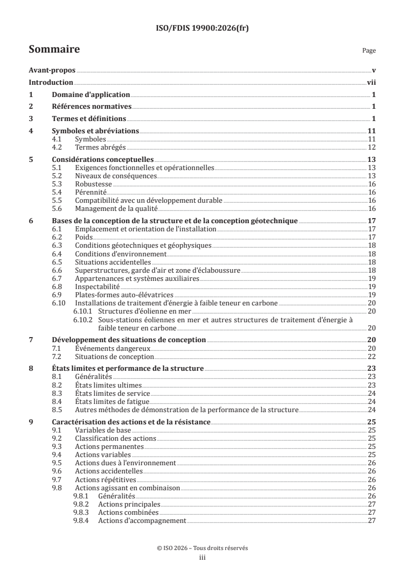
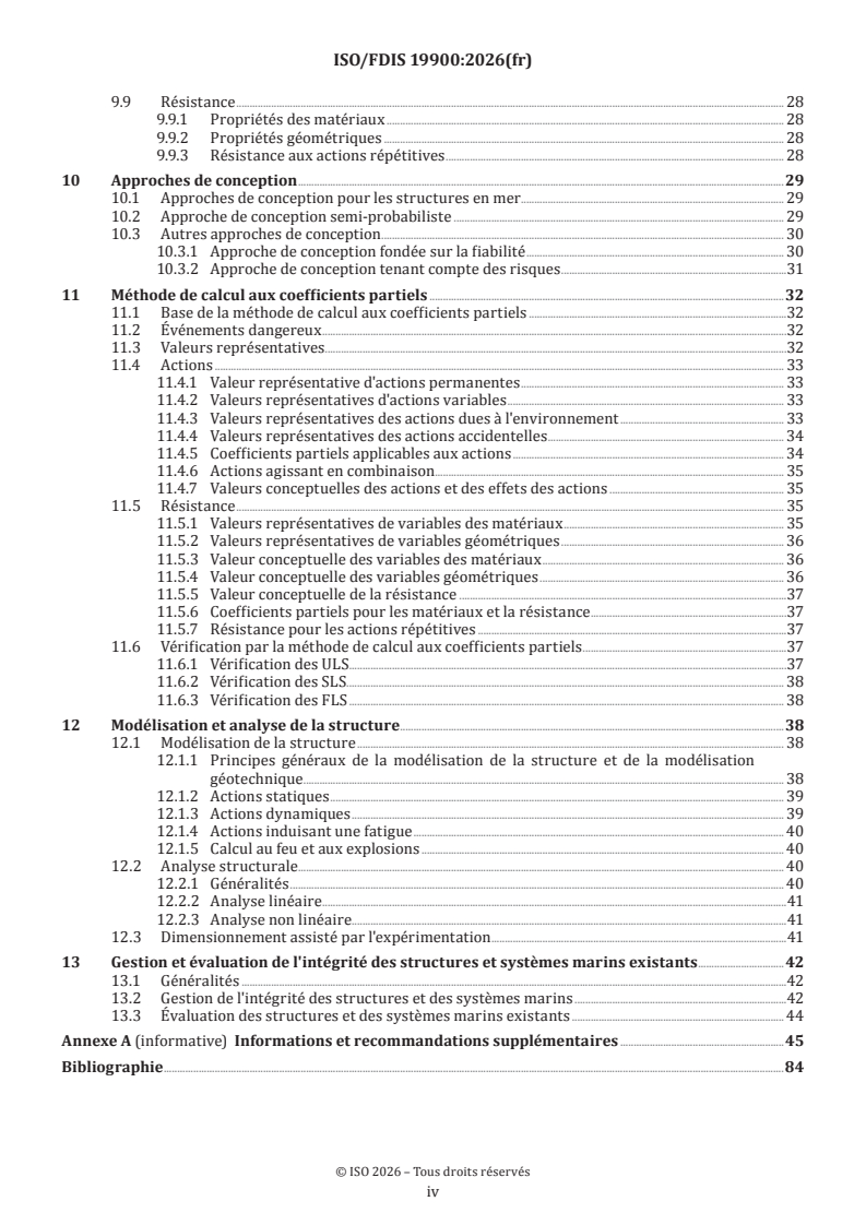
It is organized into clauses on scope, terms, symbols, design considerations, the basis of structural and geotechnical design, design situations, limit states, actions and resistance, design approaches, the partial factor design method, structural modelling and analysis, and integrity management and assessment of existing structures and marine systems. Annex A gives additional information and guidance and mirrors the clause structure for easy cross-reference.
| Annex | What it covers |
|---|---|
| Annex A | Additional information and guidance aligned with Clauses 1 to 13 |
The standard applies to all phases of the structure’s life, including pre-service activities such as fabrication, transportation, and installation, in-place service, functional upgrade, repurpose and reuse, and decommissioning and removal. It does not apply to pipelines, risers, cables, or subsea systems.
What are the key requirements of ISO/FDIS 19900?
ISO/FDIS 19900 sets the design basis, the classification of hazards and design situations, the limit-state framework, and the methods for verifying structural performance. In practice, it tells an engineer or operator what conditions to define, what checks to make, and what evidence to keep for design, assessment, and life-cycle management.
Design basis and project definition
Clause 5 requires the functional and operational requirements, including the design service life, to be specified and documented in the design basis. It also allows the design service life to be amended later if the standard’s requirements continue to be met, which matters when a facility enters life extension.
Clause 6 requires a single project datum for elevations and positions, consistent units across the project, and site-specific data for weight, marine growth, geotechnical conditions, environmental conditions, and accidental conditions. For a project team, this means the basic inputs for load cases, foundation design, and layout must be fixed and traceable before detailed verification starts.
Consequence levels, robustness, durability, sustainability, and quality management
Clause 5 classifies the structure or sub-structures into consequence levels L1, L2, or L3 before design. The consequence level is used to reflect the consequences of failure for life-safety, environmental impact, and economic loss, and it can vary by part of the facility or by design situation. In practice, that classification drives how conservative the design checks and management measures need to be.
Clause 5 also requires the structure or marine system to be robust against damage disproportionate to the initiating event, and durable enough to maintain function throughout the design service life. It expects design, assessment, inspection, monitoring, maintenance, and repair to be considered together, so corrosion, wear, fatigue, and other deterioration are not treated as afterthoughts.
The same clause calls for sustainability to be considered at design, construction, and operation, including repurposing, reuse, decommissioning, and removal. It also recommends a documented quality management system (QMS) for design, fabrication, and installation, with the extent of control aligned to the highest consequence level.
Design situations and limit states
Clause 7 requires hazardous events to be identified, documented, and translated into design situations. The document distinguishes operational, extreme, abnormal, accidental, short duration, and serviceability situations, which matters because different combinations of actions and different verification methods may apply in each case.
Clause 8 says structure performance shall be established using limit states. It recognizes ultimate limit state (ULS), serviceability limit state (SLS), and fatigue limit state (FLS), and allows alternative methods when those limit states do not fully describe the relevant performance for a particular case. For a reader, this means the standard expects you to check strength and stability, functional serviceability, and cumulative fatigue, not only one of them.
Actions, resistance, and load combinations
Clause 9 classifies actions as permanent, variable (functional), environmental, or accidental. It also requires repetitive actions to be identified where they can lead to fatigue damage, and it expects the effects of direct and indirect actions to be assessed, including combinations of principal and accompanying actions.
This matters because offshore design rarely depends on one load at a time. The standard pushes the designer to combine weights, operating loads, metocean effects, ice, seismic actions, and accidental events in a way that reflects the design situation and the likely failure mode.
Design approaches and the partial factor design method
Clause 10 sets out three design approaches: semi-probabilistic, reliability-based, and risk-informed. The semi-probabilistic approach is the default for new build structures and assessment of existing structures, while the other two approaches may be used where permitted. In practice, that means the usual route is still factored design, but the standard now permits more explicit probabilistic or risk-based treatment where justified.
Clause 11 collects the partial factor design method in one place. It requires design values for actions and resistances to be derived from representative values and calibrated partial factors, with verification against the relevant limit state. It also requires an annual probability of occurrence or return period to be associated with each hazardous event, which helps align the load model with the intended safety level.
Structural modelling, testing, and existing structures
Clause 12 covers structural modelling and analysis, including static, dynamic, fatigue, and fire and explosion design cases. It also allows design assisted by testing, for example where calculation models are limited or where testing is needed to confirm fatigue resistance, hydrodynamic factors, wind coefficients, or geotechnical properties.
Clause 13 sets the integrity management framework for structures and marine systems in service. It requires an integrity management system and strategy, current-condition data, inspection and monitoring programmes, evaluation of fitness-for-service, and assessment when changes, damage, deterioration, or life extension create uncertainty. For operators, this clause is the link between the original design basis and what is actually managed offshore over time.
What terms does ISO/FDIS 19900 define?
- Consequence level - A classification used to set design criteria according to the consequences of failure for people, the environment, and society.
- Design situation - A set of physical conditions for which the structure or a component is checked against limit-state criteria.
- Limit state - A condition beyond which the structure or component no longer satisfies the design criteria.
- Marine system - A system that contributes to the structural safety, stability, and position-keeping ability of a floating facility.
- Integrity management - The systematic process used to assure the integrity of a structure or marine system throughout its design service life.
- Partial factor method - The semi-probabilistic method that applies safety coefficients to basic variables to obtain design values.
- Semi-probabilistic design approach - A design approach that represents uncertainty and variability with factored representative values.
- Fit-for-service - A condition in which the facility complies with the applicable structural requirements for the intended use and assessment period.
Who uses ISO/FDIS 19900?
ISO/FDIS 19900 is used by structural engineers, geotechnical engineers, marine systems engineers, integrity managers, operators, and classification societies working on offshore facilities. It is relevant to offshore oil and gas, offshore wind, and other lower carbon energy structures.
In practice, users apply it to define the design basis, classify consequence levels, select design situations, check ULS, SLS, and FLS, and manage existing structures through inspection, monitoring, assessment, repair, and life extension. Buyers and quality managers also use it to judge whether a design package or integrity management plan follows a common offshore structural framework.
What changed in ISO/FDIS 19900 from the previous edition?
ISO/FDIS 19900 is the fourth edition and it replaces ISO 19900:2019. The document states these main changes:
- Provisions now apply to all structure types and marine systems, including support structures for wind turbines and associated facilities.
- Consequence levels replace exposure levels and are summarized in Table 1.
- Design situations are unchanged but are summarized in Table 2.
- Clause 10 now allows reliability-based and risk-informed design approaches in addition to the semi-probabilistic approach, with associated constraints.
- Clause 11 collects the partial factor design method in one place.
- Clause 12 adds more detailed provisions for structural modelling and analysis.
- The normative text was revised to align with IOGP Report 604 guidelines on good requirement writing and current ISO directives.
Which standards are used with ISO/FDIS 19900?
ISO/FDIS 19900 states that it has no normative references, but it is intended to be used with the ISO/TC 67/SC 7 offshore standards family and related guidance. The document links its general requirements to specific standards for metocean, seismic, geotechnical, marine operations, stationkeeping, marine soil and geophysical investigations, structural integrity management, and structure-type design.
Key companion standards named in the document include ISO 19901-1, ISO 19901-2, ISO 19901-3, ISO 19901-4, ISO 19901-5, ISO 19901-6, ISO 19901-7, ISO 19901-8, ISO 19901-9, ISO 19901-10, ISO 19902, ISO 19903, ISO 19904-1, ISO 19905-1, ISO 19906, ISO 22111, ISO 24201, ISO 29001, ISO 31000, and IEC 61400-1, IEC 61400-3-1, IEC 61400-3-2, and IEC 61400-6. In practical terms, ISO/FDIS 19900 provides the general framework, while those standards provide the detailed rules for specific structure types, site conditions, and supporting disciplines.
What does the ISO/FDIS 19900 document contain?
The document contains definition-heavy front matter, a table of symbols and abbreviated terms, the main requirement clauses, and one informative annex with guidance that mirrors the main clause structure. Its body includes Table 1 on consequence levels and Table 2 on design situations, plus detailed clause structure for actions, resistance, design approaches, partial factors, modelling, testing, and integrity management.
It also contains the methods and procedures used to build offshore structural checks, including the classification of actions, the handling of repeated actions and fatigue, and the verification of ULS, SLS, and FLS. Clause 12 adds modelling and analysis topics for static and dynamic behaviour, and the use of testing when calculation alone is not enough.
For existing structures and marine systems, the document contains the process for collecting operational and inspection data, evaluating fitness-for-service, and documenting assessment bases and performance criteria. Annex A then expands on the same topics with guidance notes rather than additional requirements, which makes it useful when a project team needs interpretation without changing the core provisions.
Relations
- Effective Date
- 12-Feb-2026
- Revises
ISO 19900:2019 - Petroleum and natural gas industries — General requirements for offshore structures - Effective Date
- 27-Jan-2024
Buy Documents
ISO/FDIS 19900 - General requirements for offshore structures
REDLINE ISO/FDIS 19900 - General requirements for offshore structures
ISO/FDIS 19900 - Exigences générales relatives aux structures en mer
Get Certified
Connect with accredited certification bodies for this standard

Element Materials Technology
Materials testing and product certification.

ABS Group Brazil
ABS Group certification services in Brazil.

ABS Quality Evaluations Inc.
American Bureau of Shipping quality certification.
Sponsored listings
Frequently Asked Questions
ISO/FDIS 19900 is a draft published by the International Organization for Standardization (ISO). Its full title is "General requirements for offshore structures". This standard covers: This document specifies general provisions for the design and assessment of fixed (bottom-founded) and floating (buoyant) offshore structures. This document contains general provisions for the design of new structures and site assessment of existing structures. This document is applicable for all phases of the life of the structure, including: ¾ pre-service (e.g., fabrication, transportation, installation), ¾ service in-place, both during originally specified design service life and during any life extensions, ¾ functional upgrade, repurpose and reuse, and ¾ decommissioning, and removal. This document focusses on primary and secondary load bearing structure but also provides some provisions for tertiary and ancillary structure. NOTE ISO 24201[22] covers the design of stairs, gratings and handrails. This document was initially created for offshore oil & gas structures but is now also applicable to renewable energy offshore structures. This document does not apply to pipelines, risers or subsea systems.
This document specifies general provisions for the design and assessment of fixed (bottom-founded) and floating (buoyant) offshore structures. This document contains general provisions for the design of new structures and site assessment of existing structures. This document is applicable for all phases of the life of the structure, including: ¾ pre-service (e.g., fabrication, transportation, installation), ¾ service in-place, both during originally specified design service life and during any life extensions, ¾ functional upgrade, repurpose and reuse, and ¾ decommissioning, and removal. This document focusses on primary and secondary load bearing structure but also provides some provisions for tertiary and ancillary structure. NOTE ISO 24201[22] covers the design of stairs, gratings and handrails. This document was initially created for offshore oil & gas structures but is now also applicable to renewable energy offshore structures. This document does not apply to pipelines, risers or subsea systems.
ISO/FDIS 19900 is classified under the following ICS (International Classification for Standards) categories: 75.180.10 - Exploratory, drilling and extraction equipment. The ICS classification helps identify the subject area and facilitates finding related standards.
ISO/FDIS 19900 has the following relationships with other standards: It is inter standard links to FprEN ISO 19900, ISO 19900:2019. Understanding these relationships helps ensure you are using the most current and applicable version of the standard.
ISO/FDIS 19900 is available in PDF format for immediate download after purchase. The document can be added to your cart and obtained through the secure checkout process. Digital delivery ensures instant access to the complete standard document.
Standards Content (Sample)
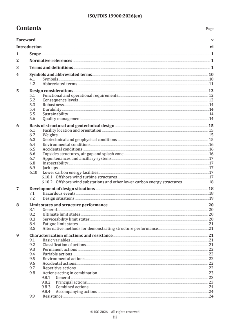
FINAL DRAFT
International
Standard
ISO/TC 67/SC 7
General requirements for offshore
Secretariat: BSI
structures
Voting begins on:
2026-09-15
Voting terminates on:
2026-11-10
RECIPIENTS OF THIS DRAFT ARE INVITED TO SUBMIT,
WITH THEIR COMMENTS, NOTIFICATION OF ANY
RELEVANT PATENT RIGHTS OF WHICH THEY ARE AWARE
AND TO PROVIDE SUPPOR TING DOCUMENTATION.
IN ADDITION TO THEIR EVALUATION AS
BEING ACCEPTABLE FOR INDUSTRIAL, TECHNO
ISO/CEN PARALLEL PROCESSING LOGICAL, COMMERCIAL AND USER PURPOSES, DRAFT
INTERNATIONAL STANDARDS MAY ON OCCASION HAVE
TO BE CONSIDERED IN THE LIGHT OF THEIR POTENTIAL
TO BECOME STAN DARDS TO WHICH REFERENCE MAY BE
MADE IN NATIONAL REGULATIONS.
Reference number
FINAL DRAFT
International
Standard
ISO/TC 67/SC 7
General requirements for offshore
Secretariat: BSI
structures
Voting begins on:
Voting terminates on:
RECIPIENTS OF THIS DRAFT ARE INVITED TO SUBMIT,
WITH THEIR COMMENTS, NOTIFICATION OF ANY
RELEVANT PATENT RIGHTS OF WHICH THEY ARE AWARE
AND TO PROVIDE SUPPOR TING DOCUMENTATION.
© ISO 2026
IN ADDITION TO THEIR EVALUATION AS
All rights reserved. Unless otherwise specified, or required in the context of its implementation, no part of this publication may
BEING ACCEPTABLE FOR INDUSTRIAL, TECHNO
ISO/CEN PARALLEL PROCESSING
LOGICAL, COMMERCIAL AND USER PURPOSES, DRAFT
be reproduced or utilized otherwise in any form or by any means, electronic or mechanical, including photocopying, or posting on
INTERNATIONAL STANDARDS MAY ON OCCASION HAVE
the internet or an intranet, without prior written permission. Permission can be requested from either ISO at the address below
TO BE CONSIDERED IN THE LIGHT OF THEIR POTENTIAL
or ISO’s member body in the country of the requester.
TO BECOME STAN DARDS TO WHICH REFERENCE MAY BE
MADE IN NATIONAL REGULATIONS.
ISO copyright office
CP 401 • Ch. de Blandonnet 8
CH-1214 Vernier, Geneva
Phone: +41 22 749 01 11
Email: copyright@iso.org
Website: www.iso.org
Published in Switzerland Reference number
ii
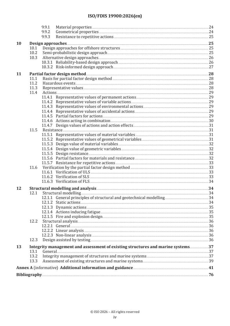
Contents Page
Foreword .v
Introduction .vi
1 Scope . 1
2 Normative references . 1
3 Terms and definitions . 1
4 Symbols and abbreviated terms.10
4.1 Symbols .10
4.2 Abbreviated terms .11
5 Design considerations .12
5.1 Functional and operational requirements . 12
5.2 Consequence levels . 12
5.3 Robustness .14
5.4 Durability .14
5.5 Sustainability .14
5.6 Quality management .14
6 Basis of structural and geotechnical design .15
6.1 Facility location and orientation . 15
6.2 Weights . 15
6.3 Geotechnical and geophysical conditions . 15
6.4 Environmental conditions .16
6.5 Accidental conditions .16
6.6 Topsides structures, air gap and splash zone .16
6.7 Appurtenances and ancillary systems .17
6.8 Inspectability .17
6.9 Jack-ups .17
6.10 Lower carbon energy facilities .17
6.10.1 Offshore wind turbine structures.17
6.10.2 Offshore wind substations and other lower carbon energy structures .18
7 Development of design situations .18
7.1 Hazardous events .18
7.2 Design situations .19
8 Limit states and structure performance . .20
8.1 General . 20
8.2 Ultimate limit states . 20
8.3 Serviceability limit states . 20
8.4 Fatigue limit states .21
8.5 Alternative methods for demonstrating structure performance .21
9 Characterization of actions and resistance.21
9.1 Basic variables .21
9.2 Classification of actions .21
9.3 Permanent actions . 22
9.4 Variable actions . 22
9.5 Environmental actions . 22
9.6 Accidental actions . 22
9.7 Repetitive actions . 22
9.8 Actions acting in combination . 23
9.8.1 General . 23
9.8.2 Principal actions . 23
9.8.3 Combined actions .24
9.8.4 Accompanying actions .24
9.9 Resistance .24
iii
9.9.1 Material properties .24
9.9.2 Geometrical properties .24
9.9.3 Resistance to repetitive actions . 25
10 Design approaches .25
10.1 Design approaches for offshore structures . 25
10.2 Semi-probabilistic design approach . 25
10.3 Alternative design approaches. 26
10.3.1 Reliability-based design approach . 26
10.3.2 Risk-informed design approach .27
11 Partial factor design method .28
11.1 Basis for partial factor design method . 28
11.2 Hazardous events . 28
11.3 Representative values . 28
11.4 Actions . 29
11.4.1 Representative values of permanent actions . 29
11.4.2 Representative values of variable actions . 29
11.4.3 Representative values of environmental actions . 29
11.4.4 Representative values of accidental actions . 29
11.4.5 Partial factors for actions . 29
11.4.6 Actions acting in combination . 30
11.4.7 Design values of actions and action effects .31
11.5 Resistance .31
11.5.1 Representative values of material variables .31
11.5.2 Representative values of geometrical variables .31
11.5.3 Design value of material variables .32
11.5.4 Design value of geometric variables .32
11.5.5 Design resistance .32
11.5.6 Partial factors for materials and resistance .32
11.5.7 Resistance for repetitive actions . 33
11.6 Verification by the partial factor design method . 33
11.6.1 Verification of ULS . 33
11.6.2 Verification of SLS . 33
11.6.3 Verification of FLS . 34
12 Structural modelling and analysis .34
12.1 Structural modelling . 34
12.1.1 General principles of structural and geotechnical modelling . 34
12.1.2 Static actions . 34
12.1.3 Dynamic actions . 35
12.1.4 Actions inducing fatigue . 35
12.1.5 Fire and explosion design . 35
12.2 Structural analysis . 36
12.2.1 General . 36
12.2.2 Linear analysis . 36
12.2.3 Non-linear analysis . 36
12.3 Design assisted by testing . 36
13 Integrity management and assessment of existing structures and marine systems.37
13.1 General .37
13.2 Integrity management of structures and marine systems .37
13.3 Assessment of existing structures and marine systems. 39
Annex A (informative) Additional information and guidance . 41
Bibliography . 76
iv
Foreword
ISO (the International Organization for Standardization) is a worldwide federation of national standards
bodies (ISO member bodies). The work of preparing International Standards is normally carried out through
ISO technical committees. Each member body interested in a subject for which a technical committee
has been established has the right to be represented on that committee. International organizations,
governmental and non-governmental, in liaison with ISO, also take part in the work. ISO collaborates closely
with the International Electrotechnical Commission (IEC) on all matters of electrotechnical standardization.
The procedures used to develop this document and those intended for its further maintenance are described
in the ISO/IEC Directives, Part 1. In particular, the different approval criteria needed for the different types
of ISO documents should be noted. This document was drafted in accordance with the editorial rules of the
ISO/IEC Directives, Part 2 (see www.iso.org/directives).
ISO draws attention to the possibility that the implementation of this document may involve the use of (a)
patent(s). ISO takes no position concerning the evidence, validity or applicability of any claimed patent
rights in respect thereof. As of the date of publication of this document, ISO had not received notice of (a)
patent(s) which may be required to implement this document. However, implementers are cautioned that
this may not represent the latest information, which may be obtained from the patent database available at
www.iso.org/patents. ISO shall not be held responsible for identifying any or all such patent rights.
Any trade name used in this document is information given for the convenience of users and does not
constitute an endorsement.
For an explanation of the voluntary nature of standards, the meaning of ISO specific terms and expressions
related to conformity assessment, as well as information about ISO's adherence to the World Trade
Organization (WTO) principles in the Technical Barriers to Trade (TBT), see www.iso.org/iso/foreword.html.
This document was prepared by Technical Committee ISO/TC 67, Oil and gas industries including lower
carbon energy, Subcommittee SC 7, Offshore structures, in collaboration with the European Committee for
Standardization (CEN) Technical Committee CEN/TC 12, Oil and gas industries including lower carbon energy,
in accordance with the Agreement on technical cooperation between ISO and CEN (Vienna Agreement).
This fourth edition cancels and replaces the third edition (ISO 19900:2019), which has been technically
revised.
The main changes are as follows:
— provisions are now applicable for all structure types and marine systems, including support structures
for wind turbines and associated facilities;
— consequence levels replace exposure levels and are summarised in Table 1;
— design situations are unchanged but are now summarized in Table 2;
— a new Clause 10 permits the use of reliability-based and risk-informed design approaches in addition to
the semi-probabilistic approach, with associated constraints;
— all provisions relating to the partial factor design method, the main method for the semi-probabilistic
design approach, have been collected in Clause 11;
— a new Clause 12 includes more detailed provisions for structural modelling and analysis;
— the normative text has been revised to conform with IOGP Report 604 Guidelines.
Any feedback or questions on this document should be directed to the user’s national standards body. A
complete listing of these bodies can be found at www.iso.org/members.html.
v
Introduction
The International Standards for offshore structures developed by ISO TC 67/SC 7 comprise:
— ISO 19900, the unifying International Standard for offshore structures;
— the ISO 19901 series, providing specific requirements for offshore structures.
— ISO 19902, ISO 19903,ISO 19904,ISO 19905 series and ISO 19906, structure-type standards.
Figure 1 illustrates the relationships between the International Standards for offshore structures developed
by ISO/TC 67/SC 7.
Figure 1 — Relationship of International Standards for offshore structures developed by
ISO/TC 67/SC 7
The International Standards for offshore structures developed by ISO/TC 67/SC 7 follow the principles of
ISO 2394 and ISO 22111 and constitutes a common basis for addressing design and assessment of offshore
structures used by the energy industries worldwide. Additional information and guidance are given in
Annex A, where the clause numbering mirrors the clauses in the body of this document to facilitate cross-
referencing.
Statements containing requirements (“shall” and “shall not”), recommendations (“should” and “should not”)
or permissions (“may”) are collectively referred to as provisions.
vi
FINAL DRAFT International Standard ISO/FDIS 19900:2026(en)
General requirements for offshore structures
1 Scope
This document contains general requirements for design of structures and marine systems and for structural
integrity management. It covers both fixed (bottom-founded) and floating (buoyant) offshore structures.
This document is applicable for all phases of the life of the structure, including:
— pre-service (e.g. fabrication, transportation, installation);
— service in-place, both during originally specified design service life and during any life extensions;
— functional upgrade, repurpose and reuse;
— decommissioning and removal.
This document focuses on primary and secondary load bearing structure but also includes some provisions
for tertiary and ancillary structure.
This document is applicable to offshore oil and gas structures, as well as lower carbon energy offshore
structures.
This document does not apply to pipelines, risers, cables or subsea systems.
2 Normative references
There are no normative references in this document.
3 Terms and definitions
For the purposes of this document, the following terms and definitions apply.
ISO and IEC maintain terminology databases for use in standardization at the following addresses:
— ISO Online browsing platform: available at https:// www .iso .org/ obp
— IEC Electropedia: available at https:// www .electropedia .org/
3.1
abnormal environmental event
environmental hazardous event (3.32) having a low probability of occurrence during the design service life
(3.18)
Note 1 to entry: The probability of occurrence selected for highest consequence level (3.12) is typically within the
−3 −4
range 10 per annum (1 in 1 000 years) to 10 per annum (1 in 10 000 years).
Note 2 to entry: Abnormal environmental events are associated with abnormal design situations (3.19), see 7.2.
3.2
accidental event
non-environmental hazardous event (3.32) having a low probability of occurrence during the design service
life (3.18)
Note 1 to entry: The probability of occurrence selected for highest consequence level (3.12) is typically within the
−3 −4
range 10 per annum (1 in 1 000 years) to 10 per annum (1 in 10 000 years).
Note 2 to entry: Accidental events are associated with a substantial release of energy, such as vessel collisions, fires
and explosions.
Note 3 to entry: Accidental events are associated with accidental design situations (3.19), see 7.2. Lesser accidents
that can be expected during the life of the structure (3.71), such as dropped objects and low-energy vessel impact, are
termed incidents (3.34) and are addressed under operational design situations (3.19).
3.3
action
external load applied to the structure (3.71) (direct load) or imposed deformation or acceleration (indirect
load)
EXAMPLE An imposed deformation can be caused by enforcing fabrication tolerances, differential settlement,
temperature change or moisture variation. An imposed acceleration can be caused by an earthquake.
Note 1 to entry: Individual action types are categorised in Clause 9.
3.4
action effect
result of actions (3.3) on a structural component (3.68), e.g. internal force, moment, stress, strain, or on the
structure (3.71), e.g. deflection, rotation
3.5
air gap
distance between the highest water surface elevation and the lowest exposed part of the deck primary
structure (3.51) not designed to withstand associated environmental action effects (3.4) for a specified
return period (3.58)
Note 1 to entry: This definition can be refined for different facility (3.27) types in their respective standards.
3.6
appurtenance
accessory or attachment to the structure (3.71) which typically assists installation, provides access or
protection, or carries fluids or gas
EXAMPLE Caisson, anodes, boat landing, fender and protection frames.
Note 1 to entry: Appurtenances do not normally contribute to the stiffness of the structure (3.71) but can attract
significant environmental loading.
3.7
ancillary system
system not under responsibility of the structural discipline or a group of appurtenances (3.6), attached to or
within the structure (3.71)
EXAMPLE Risers (3.59), subsea systems, cables, umbilicals.
3.8
basic variable
variable representing physical quantities which characterize actions (3.3) and environmental influences,
geometric quantities, and material properties including soil properties
Note 1 to entry: Basic variables are typically random variables or random processes used in the calculation or
assessment of representative values (3.56) of actions (3.3) or resistance (3.57).
3.9
calibration
process used to specify acceptance criteria for different design approaches (3.15)
Note 1 to entry: Code calibration for the partial factor method (3.49), partial factor and annual probabilities associated
with representative values (3.56) are based on experience, known cases or reliability targets. For other methods in the
semi-probabilistic design approach (3.66), this can involve the selection of safety factors.
Note 2 to entry: For methods in the reliability-based design approach (3.54), a reliability target can be calibrated to
proven safe cases or to risk indices.
3.10
characteristic value
value assigned to a basic variable (3.8) with a prescribed probability of exceedance
Note 1 to entry: A basic variable (3.8) can have two or more characteristic values, e.g. an upper value and a lower value.
3.11
conductor
tubular pipe set into the ground to provide the initial stable structural foundation for setting the surface
casing and protecting the internal well string from metocean actions (3.3)
Note 1 to entry: The conductor provides lateral and, in some cases, axial support, enables circulation of drilling fluid,
and guides the drill string to facilitate setting of the surface casing.
3.12
consequence level
classification system used to establish relevant criteria for a structure (3.71) based on consequences of
failure
3.13
damage state
discrete state that describes the level of impairment
Note 1 to entry: Damage states can be categorized between no damage and complete loss of a structure (3.71) or a
marine system (3.40).
3.14
decommissioning
process of shutting down a facility (3.27) enabling preparations for cleaning, dismantling and removal from
location at, or after, the end of its design service life (3.18)
3.15
design approach
framework used to ensure acceptable structure (3.71) performance
Note 1 to entry: Design approaches are categorized as semi-probabilistic (3.66), reliability-based (3.54) and risk-
informed (3.60).
Note 2 to entry: Different design approaches can be applied for different design situations (3.19).
Note 3 to entry: Acceptable structure (3.71) performance is achieved by satisfying limit state (3.38) criteria.
Note 4 to entry: Different design methods (3.17) can be applied within a design approach.
3.16
design criteria
quantitative formulations using design values (3.20) describing the conditions to be fulfilled for each design
situation (3.19)
3.17
design method
proven procedure, categorized within a design approach (3.15), used to demonstrate the safety of a structure
(3.71)
Note 1 to entry: Safety can involve limit state (3.38) verification, or account for relevant consequences and
uncertainties.
3.18
design service life
design life
life
planned period for which a structure (3.71) is used for its intended purpose with anticipated maintenance
(3.39), but without substantial repair (3.55) being necessary
Note 1 to entry: The originally specified design service life can be updated during the operating phase to include any
life extension periods until removal of the facility (3.27).
3.19
design situation
set of physical conditions for which the structure (3.71) or its components are subject to limit state (3.38)
verification
Note 1 to entry: Six design situations are categorised in Table 2: operational, extreme, abnormal, accidental, short
duration and serviceability.
3.20
design value
value derived from the representative value (3.56) for use in the semi-probabilistic design approach (3.66)
Note 1 to entry: Design values can be different according to the different design situations (3.19) and associated safety
partial factors.
Note 2 to entry: Design value for resistance is calculated by dividing its representative value (3.56) by a partial factor
for resistance (3.57), while design value (3.20)action effect (3.4) is calculated by multiplying its representative value
(3.56) by a partial factor for action (3.3) or action effect (3.4).
3.21
deterioration
process that adversely affects structural integrity (3.69) over time
Note 1 to entry: Deterioration can be caused by naturally occurring chemical, physical, or biological processes
including corrosion, by environmental actions (3.3), by incidents (3.34) and accidental actions (3.3), by fatigue, wear,
abrasion, and by improper operation and maintenance (3.39) of the structure (3.71).
3.22
ductility
ability of a material to deform and absorb energy beyond its elastic limit
3.23
ductility
ability of a structural component (3.68) to sustain action effects (3.4) beyond yield
3.24
ductility
ability of a structural system to deform and dissipate energy, and to redistribute action
effects (3.4)
3.25
durability
ability of a structure (3.71) or structural component (3.68) to maintain its function throughout its design
service life (3.18)
3.26
extreme environmental event
−2
environmental hazardous event (3.32) typically having probability of occurrence of 10 per annum (1 in
100 years) for highest consequence level (3.12)
Note 1 to entry: Extreme environmental events are associated with extreme design situations (3.19), see 7.2.
−2
Note 2 to entry: For offshore wind structures (3.45) and jack-ups (3.37) a probability of occurrence of 2 x 10 per
annum (1 in 50 years) is typically applied.
3.27
facility
constructions, pieces of equipment, and services that are provided for the offshore (3.43) energy sector
Note 1 to entry: The facility includes the structure (3.71) and non-structural systems such as topsides (3.73) equipment,
marine systems (3.40), piping and accommodation.
Note 2 to entry: A hydrocarbon facility (platform) includes structural appurtenances (3.6) and ancillary systems (3.7)
but does not include the non-structural components (3.68) of the hydrocarbon wells.
Note 3 to entry: The facility does not include the geological strata supporting the foundation. However, site-specific
geotechnical parameters provide the boundary conditions necessary to model the facility’s foundation or anchoring.
3.28
fit-for-service
in compliance with the applicable structural requirements
Note 1 to entry: Compliance with this standard indicates that the structure (3.71) provides the required level of
structural safety, functionality, and integrity for the defined design and operating conditions and assessment period.
Note 2 to entry: Risk-informed design approach (3.60) or reliability-based design approach (3.54) can be used to
demonstrate compliance, where permitted, see 10.3.
3.29
fixed structure
structure (3.71) that is bottom-founded and transfers most of the actions (3.3) on it to the seabed (3.64)
3.30
floating structure
structure (3.71) where the full weight is supported by buoyancy
3.31
hazard
potential source of harm
Note 1 to entry: Harm is typically differentiated between harm to people, harm to the environment, harm in terms of
costs to organizations, or harm to society in general.
3.32
hazardous event
event which occurs when a hazard (3.31) interacts with a structure (3.71)
EXAMPLE Wave impacting the structure (3.71), iceberg impacting the structure (3.71), excessive topsides (3.73)
weight added to the structure (3.71), vessel collision, fire, explosion, and landslip in the vicinity of structural anchors
(piles).
Note 1 to entry: A hazardous event can be a storm involving waves, currents and winds acting from different directions.
Note 2 to entry: A hazardous event can be a combination of basic variables (3.8) such as wave height and period, or ice
floe size and drift speed.
Note 3 to entry: A hazardous event can be an action (3.3) associated with a hazard (3.31) that involves various
combinations of basic variables (3.8).
3.33
ice gouge
ice scour
incision in the seabed (3.64) or removal of seabed (3.64) material by an ice feature
3.34
incident
non-environmental hazardous event (3.32) considered in an operational design situation (3.19)
Note 1 to entry: An incident is a lesser accidental event (3.2), associated with possible local damage or damage to
structural components (3.68), occurring with low probability, most typically associated with probabilities not less
−2
than 10 per annum (1 in 100 years).
3.35
inspection
on-site examination within the scope of quality control and condition assessment aiming to assess the
present condition of a structure (3.71)
3.36
integrity management
systematic process intended to assure integrity of a structure (3.71) or a marine system (3.40)
3.37
jack-up
mobile offshore (3.43) unit with a buoyant hull and one or more legs that can be moved up and down relative
to the hull
Note 1 to entry: A jack-up reaches its operational mode by lowering the leg(s) to the seabed (3.64) and then raising
the hull to the required elevation. The majority of jack-ups have three or more legs, each of which can be moved
independently and which are supported in the seabed (3.64) by spudcans.
3.38
limit state
state beyond which the structure (3.71) or structural component (3.68) no longer satisfies the design criteria
(3.16)
Note 1 to entry: Three limit states are categorised in Clause 8: ultimate, serviceability and fatigue.
3.39
maintenance
routine work undertaken to ensure the continuing performance of a facility (3.27)
3.40
marine system
system contributing to the structural safety, stability and position keeping ability of a floating facility (3.27)
3.41
marine system integrity
ability of a marine system (3.40) to maintain performance (3.50) throughout the design service life (3.18),
with respect to structural safety, robustness (3.61), serviceability and durability (3.25)
3.42
nominal value
value assigned to a basic variable (3.8) on a non-statistical basis, either determined from acquired experience
or physical conditions, or as specified in a published code or standard
3.43
offshore
situated in water some distance from the shore
Note 1 to entry: Alternatively, "near-shore" or “coastal” can be used to specify locations next to the coast or in mouths
of rivers.
3.44
offshore wind farm
group of offshore wind turbine structures (3.47) and offshore wind substations (3.46) in the same location
3.45
offshore wind structure
part of an offshore wind turbine facility (3.27) which extends upwards from the seabed (3.64) and connects
the foundation to the wind turbine tower, or part of an offshore wind substation (3.46) that supports the
topsides (3.73)
Note 1 to entry: The offshore wind structure can include a transition piece.
3.46
offshore wind substation
an electrical facility that collects and manages the power generated by wind turbines before transmitting it
to shore.
3.47
offshore wind turbine structure
support structure for a wind turbine assembly that is used to convert kinetic energy from the wind into
electricity
3.48
operator
owner
duty holder
principal company or company representative leasing the offshore (3.43) site from a government
3.49
partial factor method
method within the semi-probabilistic design approach (3.66) where a safety coefficient (partial factor) is
applied to basic variables (3.8) to ensure structural reliability (3.53)
Note 1 to entry: Partial factors can be applied to actions (3.3), resistances (3.57) and materials, see 11.4 and 11.5.
3.50
performance
ability of a structure (3.71) or a structural component (3.68) to fulfil specified requirements
Note 1 to entry: Specified requirements include requirements for structural functionality, structural integrity (3.69)
and functionality of marine systems (3.40).
Note 2 to entry: Performance levels are established as a means of mitigating consequences associated with life-safety,
environmental pollution, reliability (3.53) of energy supply and business disruption.
3.51
primary structure
all main structural components (3.68) that provide the structure's (3.71) main strength and stiffness
3.52
recognized classification society
RCS
member of the international association of classification societies (IACS), with recognized and relevant
competence and experience in offshore (3.43)structures (3.71) and with established rules and procedures for
classification and certification of offshore (3.43)structures (3.71) located at a specific site
3.53
re
...
Date: 2026-07-03
ISO/DISFDIS 19900:2026(en)
ISO/TC 67/SC 7/WG 1
Secretariat: BSI
Date: 2026-09-01
General requirements for offshore structures
Industries du pétrole et du gaz, y compris les énergies à faible teneur en carbone — Exigences générales
relatives aux structures en mer
This draft is submitted to a parallel vote in ISO, CEN.
FDIS stage
2 © ISO 2019 – All rights reserved
All rights reserved. Unless otherwise specified, or required in the context of its implementation, no part of this publication
may be reproduced or utilized otherwise in any form or by any means, electronic or mechanical, including photocopying,
or posting on the internet or an intranet, without prior written permission. Permission can be requested from either ISO
at the address below or ISO’s member body in the country of the requester.
ISO copyright office
CP 401 • Ch. de Blandonnet 8 • CP 401
CH-1214 Vernier, Geneva, Switzerland
Tel.Phone: + 41 22 749 01 11
Fax + 41 22 749 09 47
E-mail: copyright@iso.org
Website: www.iso.org
Published in Switzerland
iii
Contents
Foreword . vi
Introduction . viii
1 Scope . 1
2 Normative references . 1
3 Terms and definitions . 1
4 Symbols and abbreviated terms . 11
4.1 Symbols . 11
4.2 Abbreviated terms . 12
5 Design considerations . 13
5.1 Functional and operational requirements . 13
5.2 Consequence levels . 13
5.3 Robustness . 14
5.4 Durability . 15
5.5 Sustainability . 15
5.6 Quality management . 15
6 Basis of structural and geotechnical design . 16
6.1 Facility location and orientation . 16
6.2 Weights . 16
6.3 Geotechnical and geophysical conditions . 16
6.4 Environmental conditions . 16
6.5 Accidental conditions . 17
6.6 Topsides structures, air gap and splash zone . 17
6.7 Appurtenances and ancillary systems . 17
6.8 Inspectability . 18
6.9 Jack-ups . 18
6.10 Lower carbon energy facilities . 18
7 Development of design situations . 19
7.1 Hazardous events . 19
7.2 Design situations . 19
8 Limit states and structure performance. 20
8.1 General. 20
8.2 Ultimate limit states . 21
8.3 Serviceability limit states . 21
8.4 Fatigue limit states . 21
8.5 Alternative methods for demonstrating structure performance . 22
9 Characterization of actions and resistance . 22
9.1 Basic variables . 22
9.2 Classification of actions . 22
9.3 Permanent actions . 23
9.4 Variable actions . 23
9.5 Environmental actions . 23
9.6 Accidental actions . 23
9.7 Repetitive actions . 23
9.8 Actions acting in combination . 24
9.9 Resistance . 25
10 Design approaches . 26
10.1 Design approaches for offshore structures . 26
iv
10.2 Semi-probabilistic design approach . 26
10.3 Alternative design approaches . 27
11 Partial factor design method . 29
11.1 Basis for partial factor design method . 29
11.2 Hazardous events . 29
11.3 Representative values . 29
11.4 Actions . 30
11.5 Resistance . 32
11.6 Verification by the partial factor design method . 34
12 Structural modelling and analysis . 35
12.1 Structural modelling . 35
12.2 Structural analysis . 36
12.3 Design assisted by testing . 37
13 Integrity management and assessment of existing structures and marine systems . 38
13.1 General. 38
13.2 Integrity management of structures and marine systems . 38
13.3 Assessment of existing structures and marine systems . 40
Annex A (informative) Additional information and guidance . 41
Bibliography . 81
v
Foreword
ISO (the International Organization for Standardization) is a worldwide federation of national standards
bodies (ISO member bodies). The work of preparing International Standards is normally carried out through
ISO technical committees. Each member body interested in a subject for which a technical committee has been
established has the right to be represented on that committee. International organizations, governmental and
non-governmental, in liaison with ISO, also take part in the work. ISO collaborates closely with the
International Electrotechnical Commission (IEC) on all matters of electrotechnical standardization.
The procedures used to develop this document and those intended for its further maintenance are described
in the ISO/IEC Directives, Part 1. In particular, the different approval criteria needed for the different types of
ISO documents should be noted. This document was drafted in accordance with the editorial rules of the
ISO/IEC Directives, Part 2 (see www.iso.org/directives).
ISO draws attention to the possibility that the implementation of this document may involve the use of (a)
patent(s). ISO takes no position concerning the evidence, validity or applicability of any claimed patent rights
in respect thereof. As of the date of publication of this document, ISO had not received notice of (a) patent(s)
which may be required to implement this document. However, implementers are cautioned that this may not
represent the latest information, which may be obtained from the patent database available at
www.iso.org/patents. ISO shall not be held responsible for identifying any or all such patent rights.
Any trade name used in this document is information given for the convenience of users and does not
constitute an endorsement.
For an explanation of the voluntary nature of standards, the meaning of ISO specific terms and expressions
related to conformity assessment, as well as information about ISO's adherence to the World Trade
Organization (WTO) principles in the Technical Barriers to Trade (TBT), see www.iso.org/iso/foreword.html.
This document was prepared by Technical Committee ISO/TC 67, Oil and gas industries including lower carbon
energy, Subcommittee SC 7, Offshore structures., in collaboration with the European Committee for
Standardization (CEN) Technical Committee CEN/TC 12, Oil and gas industries including lower carbon energy,
in accordance with the Agreement on technical cooperation between ISO and CEN (Vienna Agreement).
This fourth edition cancels and replaces the third edition (ISO 19900:2019), which has been technically
revised.
The main changes are as follows:
— provisions are now applicable for all structure types and marine systems, including support structures for
wind turbines and associated facilities;
— consequence levels replace exposure levels and are summarised in Table 1Table 1;;
— design situations are unchanged but are now summarized in Table 2Table 2;;
— a new Clause 10Clause 10 permits the use of reliability-based and risk-informed design approaches in
addition to the semi-probabilistic approach, with associated constraints;
— all provisions relating to the partial factor design method, the main method for the semi-probabilistic
design approach, have been collected in Clause 11Clause 11;;
— a new Clause 12Clause 12 includes more detailed provisions for structural modelling and analysis;
— the normative text has been revised to complyconform with IOGP Report 604 Guidelines on good
requirement writing and current ISO directives.
vi
Any feedback or questions on this document should be directed to the user’s national standards body. A
complete listing of these bodies can be found at www.iso.org/members.html.
vii
Introduction
The International Standards for offshore structures developed by ISO TC 67/SC 7 comprise:
— — ISO 19900, the unifying International Standard for offshore structures;
[6] – [15]
— — the ISO 19901 series ,, providing specific requirements for offshore structures.
[16] [17] [18] [19]–[22] [23]
— — ISO 19902 , , ISO 19903 , ,ISO 19904 , ,ISO 19905 series and ISO 19906 ,, structure-
type standards.
Figure 1Figure 1 illustrates the relationships between the International Standards for offshore structures
developed by ISO/TC 67/SC 7.
viii
Figure 1 — Relationship of International Standards for offshore structures developed by
ISO/TC 67/SC 7
The International Standards for offshore structures developed by ISO/TC 67/SC 7 follow the principles of ISO
[1] [24]
2394 and ISO 22111 and constitutes a common basis for addressing design and assessment of offshore
structures used by the energy industries worldwide. Additional information and guidance are given in
Annex AAnnex A,, where the clause numbering mirrors the clauses in the body of this document to facilitate
cross-referencing.
Statements containing requirements (“shall” and “shall not”), recommendations (“should” and “should not”)
or permissions (“may”) are collectively referred to as provisions.
ix
General requirements for offshore structures
1 Scope
This document contains general requirements for design of structures and marine systems and for structural
integrity management. It covers both fixed (bottom-founded) and floating (buoyant) offshore structures.
This document is applicable for all phases of the life of the structure, including:
— — pre-service (e.g. fabrication, transportation, installation);
— — service in-place, both during originally specified design service life and during any life extensions;
— — functional upgrade, repurpose and reuse;
— — decommissioning and removal.
This document focuses on primary and secondary load bearing structure but also includes some provisions
for tertiary and ancillary structure.
This document is applicable to offshore oil and gas structures, as well as lower carbon energy offshore
structures.
This document does not apply to pipelines, risers, cables or subsea systems.
2 Normative references
There are no normative references in this document.
3 Terms and definitions
For the purposes of this document, the following terms and definitions apply.
ISO and IEC maintain terminology databases for use in standardization at the following addresses:
— — ISO Online browsing platform: available at https://www.iso.org/obp
— — IEC Electropedia: available at https://www.electropedia.org/
3.1 3.1
abnormal environmental event
environmental hazardous event (3.32(3.32)) having a low probability of occurrence during the design service
life (3.18(3.18))
Note 1 to entry: The probability of occurrence selected for highest consequence level (3.12(3.12)) is typically within the
−3 −4
range 10 per annum (1 in 1 000 years) to 10 per annum (1 in 10 000 years).
Note 2 to entry: Abnormal environmental events are associated with abnormal design situations (3.19(3.19),), see 7.27.2.
3.2 3.2
accidental event
non-environmental hazardous event (3.32(3.32)) having a low probability of occurrence during the design
service life (3.18(3.18))
Note 1 to entry: The probability of occurrence selected for highest consequence level (3.12(3.12) ) is typically within the
−3 −4
range 10 per annum (1 in 1 000 years) to 10 per annum (1 in 10 000 years).
Note 2 to entry: Accidental events are associated with a substantial release of energy, such as vessel collisions, fires and
explosions.
Note 3 to entry: Accidental events are associated with accidental design situations (3.19(3.19),), see 7.27.2. Lesser
accidents that can be expected during the life of the structure (3.71(3.71),), such as dropped objects and low-energy
vessel impact, are termed incidents (3.34(3.34)) and are addressed under operational design situations (3.19(3.19).).
3.3 3.3
action
external load applied to the structure (3.71(3.71)) (direct load) or imposed deformation or acceleration
(indirect load)
EXAMPLE An imposed deformation can be caused by enforcing fabrication tolerances, differential settlement,
temperature change or moisture variation. An imposed acceleration can be caused by an earthquake.
Note 1 to entry: Individual action types are categorised in Clause 9Clause 9.
3.4 3.4
action effect
result of actions (3.3(3.3)) on a structural component (3.68(3.68),), e.g. internal force, moment, stress, strain,
or on the structure (3.71(3.71),), e.g. deflection, rotation
3.5 3.5
air gap
distance between the highest water surface elevation and the lowest exposed part of the deck primary
structure (3.51(3.51)) not designed to withstand associated environmental action effects (3.4(3.4)) for a
specified return period (3.58(3.58))
Note 1 to entry: This definition can be refined for different facility (3.27(3.27)) types in their respective standards.
3.6 3.6
appurtenance
accessory or attachment to the structure (3.71(3.71)) which typically assists installation, provides access or
protection, or carries fluids or gas
EXAMPLESEXAMPLE Caisson, anodes, boat landing, fender and protection frames.
Note 1 to entry: Appurtenances do not normally contribute to the stiffness of the structure (3.71(3.71)) but can attract
significant environmental loading.
3.7 3.7
ancillary system
system not under responsibility of the structural discipline or a group of appurtenances (3.6(3.6),), attached
to or within the structure (3.71(3.71))
EXAMPLESEXAMPLE Risers (3.59(3.59),), subsea systems, cables, umbilicals.
3.8 3.8
basic variable
variable representing physical quantities which characterize actions (3.3(3.3)) and environmental influences,
geometric quantities, and material properties including soil properties
Note 1 to entry: Basic variables are typically random variables or random processes used in the calculation or assessment
of representative values (3.56(3.56)) of actions (3.3(3.3)) or resistance (3.57(3.57).).
3.9 3.9
calibration
process used to specify acceptance criteria for different design approaches (3.15(3.15))
Note 1 to entry: Code calibration for the partial factor method (3.49(3.49),), partial factor and annual probabilities
associated with representative values (3.56(3.56)) are based on experience, known cases or reliability targets. For other
methods in the semi-probabilistic design approach (3.66(3.66),), this can involve the selection of safety factors.
Note 2 to entry: For methods in the reliability-based design approach (3.54(3.54),), a reliability target can be calibrated
to proven safe cases or to risk indices.
3.10 3.10
characteristic value
value assigned to a basic variable (3.8(3.8)) with a prescribed probability of exceedance
Note 1 to entry: A basic variable (3.8(3.8)) can have two or more characteristic values, e.g. an upper value and a lower
value.
3.11 3.11
conductor
tubular pipe set into the ground to provide the initial stable structural foundation for setting the surface casing
and protecting the internal well string from metocean actions (3.3(3.3))
Note 1 to entry: The conductor provides lateral and, in some cases, axial support, enables circulation of drilling fluid, and
guides the drill string to facilitate setting of the surface casing.
3.12 3.12
consequence level
classification system used to establish relevant criteria for a structure (3.71(3.71)) based on consequences of
failure
3.13 3.13
damage state
discrete state that describes the level of impairment
Note 1 to entry: Damage states can be categorized between no damage and complete loss of a structure (3.71(3.71)) or a
marine system (3.40(3.40).).
3.14 3.14
decommissioning
process of shutting down a facility (3.27(3.27)) enabling preparations for cleaning, dismantling and removal
from location at, or after, the end of its design service life (3.18(3.18))
3.15 3.15
design approach
framework used to ensure acceptable structure (3.71(3.71)) performance
Note 1 to entry: Design approaches are categorized as semi-probabilistic (3.66(3.66),), reliability-based (3.54(3.54)) and
risk-informed (3.60(3.60).).
Note 2 to entry: Different design approaches can be applied for different design situations (3.19(3.19).).
Note 3 to entry: Acceptable structure (3.71(3.71)) performance is achieved by satisfying limit state (3.38(3.38)) criteria.
Note 4 to entry: Different design methods (3.17(3.17)) can be applied within a design approach.
3.16 3.16
design criteria
quantitative formulations using design values (3.20(3.20)) describing the conditions to be fulfilled for each
design situation (3.19(3.19))
3.17 3.17
design method
proven procedure, categorized within a design approach (3.15(3.15),), used to demonstrate the safety of a
structure (3.71(3.71))
Note 1 to entry: Safety can involve limit state (3.38(3.38)) verification, or account for relevant consequences and
uncertainties.
3.18 3.18
design service life
design life
life
planned period for which a structure (3.71(3.71)) is used for its intended purpose with anticipated
maintenance (3.39(3.39),), but without substantial repair (3.55(3.55)) being necessary
Note 1 to entry: The originally specified design service life can be updated during the operating phase to include any life
extension periods until removal of the facility (3.27(3.27).).
3.19 3.19
design situation
set of physical conditions for which the structure (3.71(3.71)) or its components are subject to limit state
(3.38(3.38)) verification
Note 1 to entry: Six design situations are categorised in Table 2Table 2:: operational, extreme, abnormal, accidental, short
duration and serviceability.
3.20 3.20
design value
value derived from the representative value (3.56(3.56)) for use in the semi-probabilistic design approach
(3.66(3.66))
Note 1 to entry: Design values can be different according to the different design situations (3.19(3.19)) and associated
safety partial factors.
Note 2 to entry: Design value for resistance is calculated by dividing its representative value (3.56(3.56)) by a partial
factor for resistance (3.57(3.57),), while design value (3.20(3.20) )action effect (3.4(3.4)) is calculated by multiplying its
representative value (3.56(3.56)) by a partial factor for action (3.3(3.3)) or action effect (3.4(3.4).).
3.21 3.21
deterioration
process that adversely affects structural integrity (3.69(3.69)) over time
Note 1 to entry: Deterioration can be caused by naturally occurring chemical, physical, or biological processes including
corrosion, by environmental actions (3.3(3.3),), by incidents (3.34(3.34)) and accidental actions (3.3(3.3),), by fatigue,
wear, abrasion, and by improper operation and maintenance (3.39(3.39)) of the structure (3.71(3.71).).
3.22 3.22
ductility
ability of a material to deform and absorb energy beyond its elastic limit
3.23 3.23
ductility
ability of a structural component (3.68(3.68)) to sustain action effects (3.4(3.4))
beyond yield
3.24 3.24
ductility
ability of a structural system to deform and dissipate energy, and to redistribute action
effects (3.4(3.4))
3.25 3.25
durability
ability of a structure (3.71(3.71)) or structural component (3.68(3.68)) to maintain its function throughout its
design service life (3.18(3.18))
3.26 3.26
extreme environmental event
−2
environmental hazardous event (3.32(3.32)) typically having probability of occurrence of 10 per annum (1
in 100 years) for highest consequence level (3.12(3.12))
Note 1 to entry: Extreme environmental events are associated with extreme design situations (3.19(3.19),), see 7.27.2.
−2
Note 2 to entry: For offshore wind structures (3.45(3.45)) and jack-ups (3.37(3.37)) a probability of occurrence of 2 x 10
per annum (1 in 50 years) is typically applied.
3.27 3.27
facility
constructions, pieces of equipment, and services that are provided for the offshore (3.43(3.43)) energy sector
Note 1 to entry: The facility includes the structure (3.71(3.71)) and non-structural systems such as topsides (3.73(3.73))
equipment, marine systems (3.40(3.40),), piping and accommodation.
Note 2 to entry: A hydrocarbon facility (platform) includes structural appurtenances (3.6(3.6)) and ancillary systems
(3.7(3.7)) but does not include the non-structural components (3.68(3.68)) of the hydrocarbon wells.
Note 3 to entry: The facility does not include the geological strata supporting the foundation. However, site-specific
geotechnical parameters provide the boundary conditions necessary to model the facility’s foundation or anchoring.
3.28 3.28
fit-for-service
in compliance with the applicable structural requirements
Note 1 to entry: Compliance with this standard indicates that the structure (3.71(3.71)) provides the required level of
structural safety, functionality, and integrity for the defined design and operating conditions and assessment period.
Note 2 to entry: Risk-informed design approach (3.60(3.60)) or reliability-based design approach (3.54(3.54)) can be used
to demonstrate compliance, where permitted, see 10.310.3.
3.29 3.29
fixed structure
structure (3.71(3.71)) that is bottom-founded and transfers most of the actions (3.3(3.3)) on it to the seabed
(3.64(3.64))
3.30 3.30
floating structure
structure (3.71(3.71)) where the full weight is supported by buoyancy
3.31 3.31
hazard
potential source of harm
Note 1 to entry: Harm is typically differentiated between harm to people, harm to the environment, harm in terms of
costs to organizations, or harm to society in general.
3.32 3.32
hazardous event
event which occurs when a hazard (3.31(3.31)) interacts with a structure (3.71(3.71))
EXAMPLESEXAMPLE Wave impacting the structure (3.71(3.71),), iceberg impacting the structure
(3.71(3.71),), excessive topsides (3.73(3.73)) weight added to the structure (3.71(3.71),), vessel collision, fire, explosion,
and landslip in the vicinity of structural anchors (piles).
Note 1 to entry: A hazardous event can be a storm involving waves, currents and winds acting from different directions.
Note 2 to entry: A hazardous event can be a combination of basic variables (3.8(3.8)) such as wave height and period, or
ice floe size and drift speed.
Note 3 to entry: A hazardous event can be an action (3.3(3.3)) associated with a hazard (3.31(3.31)) that involves various
combinations of basic variables (3.8(3.8).).
3.33 3.33
ice gouge
ice scour
incision in the seabed (3.64(3.64)) or removal of seabed (3.64(3.64)) material by an ice feature
3.34 3.34
incident
non-environmental hazardous event (3.32(3.32)) considered in an operational design situation (3.19(3.19))
Note 1 to entry: An incident is a lesser accidental event (3.2(3.2),), associated with possible local damage or damage to
structural components (3.68(3.68),), occurring with low probability, most typically associated with probabilities not less
−2
than 10 per annum (1 in 100 years).
3.35 3.35
inspection
on-site examination within the scope of quality control and condition assessment aiming to assess the present
condition of a structure (3.71(3.71))
3.36 3.36
integrity management
systematic process intended to assure integrity of a structure (3.71(3.71)) or a marine system (3.40(3.40))
3.37 3.37
jack-up
mobile offshore (3.43(3.43)) unit with a buoyant hull and one or more legs that can be moved up and down
relative to the hull
Note 1 to entry: A jack-up reaches its operational mode by lowering the leg(s) to the seabed (3.64(3.64)) and then raising
the hull to the required elevation. The majority of jack-ups have three or more legs, each of which can be moved
independently and which are supported in the seabed (3.64(3.64)) by spudcans.
3.38 3.38
limit state
state beyond which the structure (3.71(3.71)) or structural component (3.68(3.68)) no longer satisfies the
design criteria (3.16(3.16))
Note 1 to entry: Three limit states are categorised in Clause 8Clause 8:: ultimate, serviceability and fatigue.
3.39 3.39
maintenance
routine work undertaken to ensure the continuing performance of a facility (3.27(3.27))
3.40 3.40
marine system
system contributing to the structural safety, stability and position keeping ability of a floating facility
(3.27(3.27))
3.41 3.41
marine system integrity
ability of a marine system (3.40(3.40)) to maintain performance (3.50(3.50)) throughout the design service life
(3.18(3.18),), with respect to structural safety, robustness (3.61(3.61),), serviceability and durability
(3.25(3.25))
3.42 3.42
nominal value
value assigned to a basic variable (3.8(3.8)) on a non-statistical basis, either determined from acquired
experience or physical conditions, or as specified in a published code or standard
3.43 3.43
offshore
situated in water some distance from the shore
Note 1 to entry: Alternatively, "near-shore" or “coastal” can be used to specify locations next to the coast or in mouths of
rivers.
3.44 3.44
offshore wind farm
group of offshore wind turbine structures (3.47(3.47)) and offshore wind substations (3.46(3.46)) in the same
location
3.45 3.45
offshore wind structure
part of an offshore wind turbine facility (3.27(3.27)) which extends upwards from the seabed (3.64(3.64)) and
connects the foundation to the wind turbine tower, or part of an offshore wind substation (3.46(3.46)) that
supports the topsides (3.73(3.73))
Note 1 to entry: The offshore wind structure can include a transition piece.
3.46 3.46
offshore wind substation
an electrical facility that collects and manages the power generated by wind turbines before transmitting it to
shore.
3.47 3.47
offshore wind turbine structure
support structure for a wind turbine assembly that is used to convert kinetic energy from the wind into
electricity
3.48 3.48
operator
owner
duty holder
principal company or company representative leasing the offshore (3.43(3.43)) site from a government
3.49 3.49
partial factor method
method within the semi-probabilistic design approach (3.66(3.66)) where a safety coefficient (partial factor)
is applied to basic variables (3.8(3.8)) to ensure structural reliability (3.53(3.53))
Note 1 to entry: Partial factors can be applied to actions (3.3(3.3),), resistances (3.57(3.57)) and materials, see 11.411.4
and 11.511.5.
3.50 3.50
performance
ability of a structure (3.71(3.71)) or a structural component (3.68(3.68)) to fulfil specified requirements
Note 1 to entry: Specified requirements include requirements for structural functionality, structural integrity
(3.69(3.69)) and functionality of marine systems (3.40(3.40).).
Note 2 to entry: Performance levels are established as a means of mitigating consequences associated with life-safety,
environmental pollution, reliability (3.53(3.53)) of energy supply and business disruption.
3.51 3.51
primary structure
all main structural components (3.68(3.68)) that provide the structure's (3.71(3.71)) main strength and
stiffness
3.52 3.52
recognized classification society
RCS
member of the international association of classification societies (IACS), with recognized and relevant
competence and experience in offshore (3.43(3.43) )structures (3.71(3.71)) and with established rules and
procedures for classification and certification of offshore (3.43(3.43) )structures (3.71(3.71)) located at a
specific site
3.53 3.53
reliability
performance (3.50(3.50)) over a specified time period
Note 1 to entry: When reliability is used in the context of limit states (3.38(3.38),), it can be expressed as the probability
that the limit is not exceeded.
Note 2 to entry: The specified time period is typically one year.
3.54 3.54
reliability-based design approach
design approach (3.15(3.15)) where uncertainty and variability in the basic variables (3.8(3.8)) are
represented by means of probabilistic methods and models
Note 1 to entry: This approach is based on probabilistic models of action effects and resistances, e.g. FORM, SORM, Monte-
Carlo simulations, or hazard and fragility curves.
3.55 3.55
repair
restoring the condition of a structure (3.71(3.71)) that has been damaged or deteriorated
3.56 3.56
representative value
value used in the semi-probabilistic design approach (3.66(3.66)) based on the characteristic value (3.10(3.10))
or the nominal value (3.42(3.42)) or a combination of characteristic values (3.10(3.10)) and nominal values
(3.42(3.42))
Note 1 to entry: For strength models, a representative value can be either a characteristic value (3.10(3.10)) or a nominal
value (3.42(3.42)) while for action models, a representative value can usually be calculated from a combination of
characteristic values (3.10(3.10)) and nominal values (3.42(3.42).).
3.57 3.57
resistance
ability of a structure (3.71(3.71),), or a structural component (3.68(3.68),), to withstand action effects
(3.4(3.4))
3.58 3.58
return period
average time between occurrences of an event
Note 1 to entry: The offshore (3.43(3.43)) industry commonly uses a return period measured in years for environmental
events. The return period in years is equal to the reciprocal of the annual probability of occurrence of the event.
Note 2 to entry: Events include both discrete hazardous events (3.32(3.32)) and exceedances of a threshold of a relevant
variable.
3.59 3.59
riser
pipe designed to carry fluids (typically hydrocarbons) between the sea floor (3.63(3.63)) and a termination
point on a facility (3.27(3.27))
Note 1 to entry: For fixed structures (3.29(3.29),), the termination point is usually the topsides (3.73(3.73).).
Note 2 to entry: For floating structures (3.30(3.30),), the riser can terminate at other locations on the facility (3.27(3.27).).
3.60 3.60
risk-informed design approach
design approach (3.15(3.15)) where uncertainty and variability in both the basic variables (3.8(3.8)) and the
consequences are represented by proven risk assessment methods
Note 1 to entry: Depending on the design situation (3.19(3.19),), consequences can include life-safety, environmental
pollution, reliability of energy supply and business disruption.
Note 2 to entry: Uncertainty and variability in basic variables (3.8(3.8)) and hazardous events (3.32(3.32)) are typically
represented by probabilistic methods and models.
Note 3 to entry: Uncertainty and variability in consequences are often modelled by their expected value but can also be
represented by probabilistic methods and models.
3.61 3.61
robustness
ability of a structure (3.71(3.71)) to withstand hazardous events (3.32(3.32)) without being damaged to an
extent disproportionate to the cause
3.62 3.62
scour
removal of seabed (3.64(3.64)) material caused by currents and waves
3.63 3.63
sea floor
interface between sea and seabed (3.64(3.64))
3.64 3.64
seabed
materials below the sea floor (3.63(3.63))
3.65 3.65
secondary structure
structural components (3.68(3.68)) that, when removed, do not significantly alter the overall strength and
stiffness of the structure (3.71(3.71))
3.66 3.66
semi-probabilistic design approach
design approach (3.15(3.15)) where uncertainty and variability in the basic variables (3.8(3.8)) are
represented by factored representative values (3.56(3.56))
Note 1 to entry: Partial factor method (3.49(3.49),), working stress method and event-based design method are
categorized within this approach.
3.67 3.67
splash zone
part of a structure (3.71(3.71)) that is intermittently exposed to air and immersed in the sea
3.68 3.68
structural component
discrete part of a structure (3.71(3.71))
EXAMPLE Examples of components include columns, beams, stiffened plates, tubulars and joints, mooring lines and
tendons, foundation anchors and piles, but not the geological strata.
Note 1 to entry: A component can include an assembly of components, e.g. a subsystem.
3.69 3.69
structural integrity
ability of a structure (3.71(3.71)) or a structural component (3.68(3.68)) to maintain performance (3.50(3.50))
throughout the design service life (3.18(3.18),), with respect to structural safety, robustness (3.61(3.61),),
serviceability and durability (3.25(3.25))
3.70 3.70
structural reliability analysis
probabilistic methodology for determining limit state (3.38(3.38)) or damage state exceedance probabilities
3.71 3.71
structure
organized combination of physically connected elements designed to withstand actions (3.3(3.3)) and provide
adequate rigidity
3.72 3.72
tertiary structure
non-loadbearing elements associated with outfitting offshore (3.43(3.43)) energy facilities (3.27(3.27))
EXAMPLESEXAMPLE Handrails, guardrails, safety gates, stairs, ladders, staircases, floor gratings, kick plates,
drip pans, cable trays, pipe supports, vents, access covers, manhole covers, attachments for corrosion protection systems.
[25]
Note 1 to entry: ISO 24201 covers the design of tertiary outfitting structures.
3.73 3.73
topsides
structure (3.71(3.71)) and equipment placed on a supporting fixed structure (3.29(3.29)) or floating structure
(3.30(3.30)) to provide some or all of a facility’s (3.27(3.27)) functions
Note 1 to entry: For a ship-shaped floating structure (3.30(3.30),), the hull deck is not part of the topsides (3.73(3.73).).
Note 2 to entry: For a jack-up (3.37(3.37),), the hull is not part of the topsides (3.73(3.73).).
Note 3 to entry: A separate fabricated deck or module support frame is part of the topsides (3.73(3.73).).
Note 4 to entry: For an offshore wind turbine facility (3.27(3.27),), the topsides (3.73(3.73)) comprise the wind turbine
tower and the rotor-nacelle assembly.
4 Symbols and abbreviated terms
4.1 Symbols
A accidental action
a design value of geometric variable
d
a representative value of geometric variable
r
C design value of the deformation or constraint
d
E environmental action
E repetitive environmental action
R
E environmental action with a specified return period
RP
F action
F design action
d
F representative value of an action
r
f design value of material variable
d
f representative value of material variable
r
G permanent action
N numbers of cycles to failure for different stress, strain or action levels
p annual probability of occurrence or probability of exceedance
Q variable (functional) action
Q repetitive variable (functional) action
R
Q variable action of long duration
Q variable action of short duration
R reliability of a structural system
R design value of resistance
d
R representative value of resistance
r
S total design action effect
d
T annual return period of an event or an action
γ partial factor for environmental action
E
γ partial factor for action
F
γ partial factor for material
M
γ partial factor for resistance
R
Δa additive deviation in the geometric variable
4.2 Abbreviated terms
ALARP as low as reasonably practicable
ALE abnormal level earthquake (from ISO 19901-2)
ALS procedure for limit state verification of abnormal and accidental design situations
COV coefficient of variation
DS damage state
DL damage limitation (type of damage state, from ISO 19901-3)
DLB ductility level blast (from ISO 19901-3)
ELE extreme level earthquake (from ISO 19901-2)
...
PROJET FINAL
Norme
internationale
ISO/TC 67/SC 7
Exigences générales relatives aux
Secrétariat: BSI
structures en mer
Début de vote:
General requirements for offshore structures 2026-09-15
Vote clos le:
2026-11-10
LES DESTINATAIRES DU PRÉSENT PROJET SONT
INVITÉS À PRÉSENTER, AVEC LEURS OBSERVATIONS,
NOTIFICATION DES DROITS DE PROPRIÉTÉ DONT ILS
AURAIENT ÉVENTUELLEMENT CONNAISSANCE ET À
FOURNIR UNE DOCUMENTATION EXPLICATIVE.
OUTRE LE FAIT D’ÊTRE EXAMINÉS POUR
ÉTABLIR S’ILS SONT ACCEPTABLES À DES FINS
INDUSTRIELLES, TECHNOLOGIQUES ET COM-MERCIALES,
AINSI QUE DU POINT DE VUE DES UTILISATEURS, LES
PROJETS DE NORMES
TRAITEMENT PARALLÈLE ISO/CEN
INTERNATIONALES DOIVENT PARFOIS ÊTRE CONSIDÉRÉS
DU POINT DE VUE DE LEUR POSSI BILITÉ DE DEVENIR DES
NORMES POUVANT
SERVIR DE RÉFÉRENCE DANS LA RÉGLEMENTATION
NATIONALE.
Numéro de référence
PROJET FINAL
Norme
internationale
ISO/TC 67/SC 7
Exigences générales relatives aux
Secrétariat: BSI
structures en mer
Début de vote:
General requirements for offshore structures
2026-09-15
Vote clos le:
2026-11-10
DOCUMENT PROTÉGÉ PAR COPYRIGHT
© ISO 2026
LES DESTINATAIRES DU PRÉSENT PROJET SONT
Tous droits réservés.
INVITÉS À PRÉSENTER, AVEC LEURS OBSERVATIONS,
NOTIFICATION DES DROITS DE PROPRIÉTÉ DONT ILS
La présente publication de l’ISO est protégée par le droit d’auteur et demeure la propriété de l’ISO et/ou de ses concédants de
AURAIENT ÉVENTUELLEMENT CONNAISSANCE ET À
licence.
FOURNIR UNE DOCUMENTATION EXPLICATIVE.
Le contenu de la présente publication de l’ISO est fourni sous licence, et n’est pas vendu. Son utilisation est soumise aux conditions
OUTRE LE FAIT D’ÊTRE EXAMINÉS POUR
ÉTABLIR S’ILS SONT ACCEPTABLES À DES FINS
de licence applicables définies par l’ISO, un organisme membre de l’ISO, ou un distributeur tiers agréé.
INDUSTRIELLES, TECHNOLOGIQUES ET COM-MERCIALES,
Sous réserve des besoins liés à sa mise en œuvre ou d’une autorisation expresse prévue aux termes d’une licence distincte, aucune
AINSI QUE DU POINT DE VUE DES UTILISATEURS, LES
partie de la présente publication de l’ISO ne peut être reproduite, distribuée, modifiée, utilisée ou mise à disposition sous quelque PROJETS DE NORMES
TRAITEMENT PARALLÈLE ISO/CEN
INTERNATIONALES DOIVENT PARFOIS ÊTRE CONSIDÉRÉS
forme ou par quelque moyen que ce soit – électronique ou mécanique, y compris la photocopie, la numérisation, l’enregistrement
DU POINT DE VUE DE LEUR POSSI BILITÉ DE DEVENIR DES
ou la publication sur des plateformes numériques internes ou externes.
NORMES POUVANT
SERVIR DE RÉFÉRENCE DANS LA RÉGLEMENTATION
Toute utilisation hors du champ d’application des droits accordés est interdite et peut donner lieu à des poursuites judiciaires.
NATIONALE.
ISO copyright office
Case postale 401 • CH-1214 Vernier, Genève
Tél.: +41 22 749 01 11
E-mail: copyright@iso.org
Web: www.iso.org
Publié en Suisse
Numéro de référence
ii
Sommaire Page
Avant-propos .v
Introduction .vii
1 Domaine d'application . 1
2 Références normatives . 1
3 Termes et définitions . 1
4 Symboles et abréviations .11
4.1 Symboles .11
4.2 Termes abrégés . 12
5 Considérations conceptuelles .13
5.1 Exigences fonctionnelles et opérationnelles . 13
5.2 Niveaux de conséquences . 13
5.3 Robustesse .16
5.4 Pérennité .16
5.5 Compatibilité avec un développement durable .16
5.6 Management de la qualité .16
6 Bases de la conception de la structure et de la conception géotechnique . 17
6.1 Emplacement et orientation de l'installation .17
6.2 Poids .17
6.3 Conditions géotechniques et géophysiques .18
6.4 Conditions d'environnement .18
6.5 Situations accidentelles .18
6.6 Superstructures, garde d'air et zone d'éclaboussure .18
6.7 Appartenances et systèmes auxiliaires .19
6.8 Inspectabilité .19
6.9 Plates-formes auto-élévatrices .19
6.10 Installations de traitement d'énergie à faible teneur en carbone . 20
6.10.1 Structures d'éolienne en mer . 20
6.10.2 Sous-stations éoliennes en mer et autres structures de traitement d'énergie à
faible teneur en carbone . 20
7 Développement des situations de conception .20
7.1 Événements dangereux . 20
7.2 Situations de conception . 22
8 États limites et performance de la structure .23
8.1 Généralités . 23
8.2 États limites ultimes . . 23
8.3 États limites de service .24
8.4 États limites de fatigue.24
8.5 Autres méthodes de démonstration de la performance de la structure .24
9 Caractérisation des actions et de la résistance .25
9.1 Variables de base . 25
9.2 Classification des actions . 25
9.3 Actions permanentes . 25
9.4 Actions variables . 25
9.5 Actions dues à l'environnement . 26
9.6 Actions accidentelles . 26
9.7 Actions répétitives . 26
9.8 Actions agissant en combinaison . 26
9.8.1 Généralités . 26
9.8.2 Actions principales .27
9.8.3 Actions combinées .27
9.8.4 Actions d'accompagnement .27
iii
9.9 Résistance . 28
9.9.1 Propriétés des matériaux . 28
9.9.2 Propriétés géométriques . 28
9.9.3 Résistance aux actions répétitives . 28
10 Approches de conception .29
10.1 Approches de conception pour les structures en mer . 29
10.2 Approche de conception semi-probabiliste . 29
10.3 Autres approches de conception . 30
10.3.1 Approche de conception fondée sur la fiabilité . 30
10.3.2 Approche de conception tenant compte des risques .31
11 Méthode de calcul aux coefficients partiels .32
11.1 Base de la méthode de calcul aux coefficients partiels .32
11.2 Événements dangereux .32
11.3 Valeurs représentatives . .32
11.4 Actions . 33
11.4.1 Valeur représentative d'actions permanentes . 33
11.4.2 Valeurs représentatives d'actions variables . 33
11.4.3 Valeurs représentatives des actions dues à l'environnement . 33
11.4.4 Valeurs représentatives des actions accidentelles . 34
11.4.5 Coefficients partiels applicables aux actions . 34
11.4.6 Actions agissant en combinaison. 35
11.4.7 Valeurs conceptuelles des actions et des effets des actions . 35
11.5 Résistance . 35
11.5.1 Valeurs représentatives de variables des matériaux . 35
11.5.2 Valeurs représentatives de variables géométriques . 36
11.5.3 Valeur conceptuelle des variables des matériaux . 36
11.5.4 Valeur conceptuelle des variables géométriques . 36
11.5.5 Valeur conceptuelle de la résistance .37
11.5.6 Coefficients partiels pour les matériaux et la résistance .37
11.5.7 Résistance pour les actions répétitives .37
11.6 Vérification par la méthode de calcul aux coefficients partiels .37
11.6.1 Vérification des ULS.37
11.6.2 Vérification des SLS. 38
11.6.3 Vérification des FLS . 38
12 Modélisation et analyse de la structure . .38
12.1 Modélisation de la structure . 38
12.1.1 Principes généraux de la modélisation de la structure et de la modélisation
géotechnique . 38
12.1.2 Actions statiques . 39
12.1.3 Actions dynamiques . 39
12.1.4 Actions induisant une fatigue . 40
12.1.5 Calcul au feu et aux explosions . 40
12.2 Analyse structurale . . 40
12.2.1 Généralités . 40
12.2.2 Analyse linéaire .41
12.2.3 Analyse non linéaire . .41
12.3 Dimensionnement assisté par l'expérimentation .41
13 Gestion et évaluation de l'intégrité des structures et systèmes marins existants .42
13.1 Généralités .42
13.2 Gestion de l'intégrité des structures et des systèmes marins .42
13.3 Évaluation des structures et des systèmes marins existants . 44
Annexe A (informative) Informations et recommandations supplémentaires .45
Bibliographie .84
iv
Avant-propos
L'ISO (Organisation internationale de normalisation) est une fédération mondiale d'organismes nationaux
de normalisation (comités membres de l'ISO). L'élaboration des Normes internationales est en général
confiée aux comités techniques de l'ISO. Chaque comité membre intéressé par une étude a le droit de faire
partie du comité technique créé à cet effet. Les organisations internationales, gouvernementales et non
gouvernementales, en liaison avec l'ISO participent également aux travaux. L'ISO collabore étroitement avec
la Commission électrotechnique internationale (IEC) en ce qui concerne la normalisation électrotechnique.
Les procédures utilisées pour élaborer le présent document et celles destinées à sa mise à jour sont
décrites dans les Directives ISO/IEC, Partie 1. Il convient, en particulier, de prendre note des différents
critères d'approbation requis pour les différents types de documents ISO. Le présent document
a été rédigé conformément aux règles de rédaction données dans les Directives ISO/IEC, Partie 2
(voir www.iso.org/directives).
L'ISO attire l'attention sur le fait que la mise en application du présent document peut entraîner l'utilisation
d'un ou de plusieurs brevets. L'ISO ne prend pas position quant à la preuve, à la validité et à l'applicabilité de
tout droit de propriété revendiqué à cet égard. À la date de publication du présent document, l'ISO n'avait pas
reçu notification qu'un ou plusieurs brevets pouvaient être nécessaires à sa mise en application. Toutefois,
il y a lieu d'avertir les responsables de la mise en application du présent document que des informations
plus récentes sont susceptibles de figurer dans la base de données de brevets, disponible à l'adresse
www.iso.org/brevets. L'ISO ne saurait être tenue pour responsable de ne pas avoir identifié de tels droits de
propriété et averti de leur existence.
Les appellations commerciales éventuellement mentionnées dans le présent document sont données pour
information, par souci de commodité, à l'intention des utilisateurs et ne sauraient constituer un engagement.
Pour une explication de la nature volontaire des normes, la signification des termes et expressions
spécifiques de l'ISO liés à l'évaluation de la conformité, ou pour toute information au sujet de l'adhésion de
l'ISO aux principes de l'Organisation mondiale du commerce (OMC) concernant les obstacles techniques au
commerce (OTC), voir www.iso.org/avant-propos.
Le présent document a été élaboré par le comité technique ISO/TC 67, Industries du pétrole et du gaz, y
compris les énergies à faible teneur en carbone, sous-comité SC 7, Structures en mer, en collaboration avec le
comité technique CEN/TC 12, Industries du pétrole et du gaz, y compris les énergies à faible teneur en carbone
du Comité européen de normalisation (CEN), conformément à l'Accord de coopération technique entre l'ISO
et le CEN (Accord de Vienne).
Cette quatrième édition annule et remplace la troisième édition (ISO 19900:2019), qui a fait l'objet d'une
révision technique.
Les principales modifications sont les suivantes:
— les dispositions s'appliquent désormais à tous les types de structures et aux systèmes marins, y compris
les structures de support pour les éoliennes et les installations associées;
— les niveaux de conséquences remplacent les niveaux d'exposition et sont résumés dans le Tableau 1;
— les situations de conception sont inchangées, mais sont désormais résumées dans le Tableau 2;
— un nouvel Article 10 permet l'utilisation d'approches de conception fondées sur la fiabilité et tenant
compte des risques en plus de l'approche semi-probabiliste, avec les contraintes associées;
— toutes les dispositions relatives à la méthode de calcul aux coefficients partiels, la méthode principale
pour l'approche de conception semi-probabiliste, ont été recueillies à l'Article 11;
— un nouvel Article 12 comprend des dispositions plus détaillées pour la modélisation et l'analyse
structurales;
— le texte normatif a été révisé pour se conformer aux Lignes directrices de l'IOGP Report 604.
v
Il convient que l'utilisateur adresse tout retour d'information ou toute question concernant le présent
document à l'organisme national de normalisation de son pays. Une liste exhaustive desdits organismes se
trouve à l'adresse www.iso.org/fr/members.html.
vi
Introduction
Les Normes internationales pour les structures en mer élaborées par l'ISO TC 67/SC 7 comprennent:
— l'ISO 19900, la Norme internationale unificatrice pour les structures en mer;
— la série ISO 19901, fournissant des exigences spécifiques pour les structures en mer;
— l'ISO 19902, l'ISO 19903, la série ISO 19904, la série ISO 19905 et l'ISO 19906, des normes portant sur un
«type de structure».
La Figure 1 illustre les relations entre les Normes internationales pour les structures en mer élaborées par
l'ISO/TC 67/SC 7.
Figure 1 — Relations entre les Normes internationales pour les structures en mer élaborées par
l'ISO/TC 67/SC 7
Les Normes internationales pour les structures en mer élaborées par l'ISO/TC 67/SC 7 suivent les principes
de l'ISO 2394 et de l'ISO 22111, et constituent une base commune pour le traitement de la conception et de
l'évaluation des structures en mer utilisées par les industries de l'énergie dans le monde. Des informations
et recommandations supplémentaires sont données à l'Annex A, dont la numérotation correspond à celle des
articles dans le corps du présent document pour faciliter la consultation.
Les déclarations contenant les exigences («doit» et «ne doit pas»), les recommandations («il convient
que» et «il ne convient pas que») ou les autorisations («peut») sont collectivement désignées en tant que
«dispositions».
vii
PROJET FINAL Norme internationale ISO/FDIS 19900:2026(fr)
Exigences générales relatives aux structures en mer
1 Domaine d'application
Le présent document contient des exigences générales pour la conception des structures et systèmes marins
et pour la gestion de l'intégrité structurelle. Il couvre à la fois les structures en mer fixes (prenant appui sur
le fond marin) et les structures en mer flottantes.
Le présent document s'applique à toutes les phases de la durée de vie de la structure, y compris:
— avant l'exploitation (par exemple, la fabrication, le transport, l'installation);
— l'exploitation, à la fois pendant la durée de vie en service initialement spécifiée et pendant toute
prolongation de la durée de vie;
— la mise à niveau, la réaffectation et la réutilisation fonctionnelles;
— l'abandon et l'enlèvement.
Le présent document se concentre sur les structures portantes primaires et secondaires, mais comprend
également certaines dispositions pour les structures tertiaires et auxiliaires.
Le présent document s'applique aux structures en mer pour le pétrole et le gaz, ainsi qu'aux structures en
mer de traitement d'énergie à faible teneur en carbone.
Le présent document ne s'applique pas aux systèmes de conduites, aux systèmes de tubes prolongateurs, aux
systèmes de câbles ou aux systèmes sous-marins.
2 Références normatives
Le présent document ne contient aucune référence normative.
3 Termes et définitions
Pour les besoins du présent document, les termes et définitions suivants s'appliquent.
L'ISO et l'IEC tiennent à jour des bases de données terminologiques destinées à être utilisées en normalisation,
consultables aux adresses suivantes:
— ISO Online browsing platform: disponible à l'adresse https:// www .iso .org/ obp
— IEC Electropedia: disponible à l'adresse https:// www .electropedia .org/
3.1
événement environnemental anormal
événement dangereux (3.32) environnemental ayant une faible probabilité d'occurrence au cours de la durée
de vie en service (3.18)
Note 1 à l'article: La probabilité d'occurrence choisie pour le niveau de conséquences (3.12) le plus élevé se situe
−3 −4
généralement dans la plage de 10 par an (1 tous les 1 000 ans) à 10 par an (1 tous les 10 000 ans).
Note 2 à l'article: Les événements environnementaux anormaux sont associés à des situations de conception (3.19)
anormales, voir 7.2.
3.2
événement accidentel
événement dangereux (3.32) non environnemental ayant une faible probabilité d'occurrence au cours de la
durée de vie en service (3.18)
Note 1 à l'article: La probabilité d'occurrence choisie pour le niveau de conséquences (3.12) le plus élevé se situe
−3 −4
généralement dans la plage de 10 par an (1 tous les 1 000 ans) à 10 par an (1 tous les 10 000 ans).
Note 2 à l'article: Les événements accidentels sont associés à une libération importante d'énergie, par exemple lors de
collisions avec un navire, d'incendies et d'explosions.
Note 3 à l'article: Les événements accidentels sont associés à des situations de conception (3.19) accidentelles, voir 7.2.
Les accidents de plus faible ampleur qui peuvent être attendus au cours de la durée de vie de la structure (3.71), par
exemple la chute d'objets et des chocs de faible énergie avec un navire, sont appelés incidents (3.34) et sont traités dans
le cadre de situations de conception (3.19) d'exploitation.
3.3
action
charge extérieure appliquée à la structure (3.71) (charge directe) ou déformation ou accélération imposée
(charge indirecte)
EXEMPLE Une déformation imposée peut être causée en appliquant des tolérances de fabrication, un tassement
différentiel ou des variations de température ou d'humidité. Une accélération imposée peut être causée par un séisme.
Note 1 à l'article: Les types d'action individuels sont classés à l'Article 9.
3.4
effet des actions
résultat des actions (3.3) sur un élément de structure (3.68), par exemple: force interne, moment, contrainte,
déformation, ou sur la structure (3.71), par exemple: flexion, rotation
3.5
garde d'air
distance entre le niveau le plus élevé de la surface de l'eau et la partie exposée la plus basse de la structure
primaire (3.51) du pont, qui n'est pas conçue pour supporter les effets des actions (3.4) dues à l'environnement
pendant une période de retour (3.58) spécifiée
Note 1 à l'article: Cette définition peut être précisée pour différents types d'installations (3.27) dans leurs normes
respectives.
3.6
appartenances
accessoire ou fixation sur la structure (3.71) qui aide généralement à l'installation, assure l'accès ou la
protection, ou transporte des fluides ou des gaz
EXEMPLE Caisson, anodes, débarcadères, dispositif défense et cadres de protection.
Note 1 à l'article: Les appartenances ne contribuent normalement pas à la rigidité de la structure (3.71), mais peuvent
faire l'objet d'importantes charges environnementales.
3.7
système auxiliaire
système non soumis à la responsabilité de la discipline structurelle ou d'un groupe d'appartenances (3.6),
fixé à la structure (3.71) ou à l'intérieur de celle-ci
EXEMPLE Tubes prolongateurs (3.59), systèmes sous-marins, câbles, câbles ombilicaux.
3.8
variable de base
variable se rapportant aux grandeurs physiques qui caractérisent les actions (3.3) et les incidences de
l'environnement, les grandeurs géométriques et les propriétés des matériaux, y compris les propriétés des
sols
Note 1 à l'article: Les variables de base sont généralement des variables aléatoires ou des processus aléatoires utilisés
dans le calcul ou l'évaluation des valeurs représentatives (3.56) d'actions (3.3) ou de résistance (3.57).
3.9
calibration
processus utilisé pour spécifier les critères d'acceptation pour différentes approches de conception (3.15)
Note 1 à l'article: La calibration de code pour la méthode aux coefficients partiels (3.49), le coefficient partiel et les
probabilités annuelles associés aux valeurs représentatives (3.56) sont basés sur l'expérience, les cas connus ou les
objectifs de fiabilité. Pour d'autres méthodes dans l'approche de conception semi-probabiliste (3.66), cela peut impliquer
le choix de coefficients de sécurité.
Note 2 à l'article: Pour les méthodes dans l'approche de conception fondée sur la fiabilité (3.54), un objectif de fiabilité
peut être calibré par rapport à des cas sûrs avérés ou à des indices de risque.
3.10
valeur caractéristique
valeur attribuée à une variable de base (3.8) avec une probabilité de dépassement donnée
Note 1 à l'article: Une variable de base (3.8) peut avoir deux valeurs caractéristiques ou plus, par exemple une valeur
supérieure et une valeur inférieure.
3.11
tube conducteur
canalisation tubulaire installée dans le sol pour assurer une fondation structurelle initiale stable, afin
d'installer l'enveloppe de surface et de protéger la ligne interne du puits des actions (3.3)
océano-météorologiques
Note 1 à l'article: Le tube conducteur fournit un support latéral (et dans certains cas axial), permet la circulation des
fluides de forage et guide la garniture de forage afin de faciliter l'installation du tubage de surface.
3.12
niveau de conséquences
système de classification utilisé pour établir les critères pertinents pour une structure (3.71) à partir des
conséquences d'une ruine structurelle
3.13
état d'endommagement
état discret qui décrit le niveau de dégradation
Note 1 à l'article: Les états d'endommagement peuvent être classés entre l'absence d'endommagement et la perte
complète d'une structure (3.71) ou d'un système marin (3.40).
3.14
abandon
processus qui consiste à arrêter l'exploitation d'une installation (3.27), permettant la préparation des
opérations de nettoyage, de démontage et d'enlèvement à, ou après, la fin de sa durée de vie en service (3.18)
3.15
approche de conception
cadre utilisé pour assurer des performances de structure (3.71) acceptables
Note 1 à l'article: Les approches de conception sont classées comme semi-probabiliste (3.66), fondée sur la fiabilité
(3.54) et tenant compte des risques (3.60).
Note 2 à l'article: Différentes approches de conception peuvent être appliquées pour différentes situations de conception
(3.19).
Note 3 à l'article: Des performances de structure (3.71) acceptables sont obtenues en satisfaisant à des critères d'état
limite (3.38).
Note 4 à l'article: Différentes méthodes de conception (3.17) peuvent être appliquées au sein d'une approche de
conception.
3.16
critères de conception
formulations quantitatives utilisant les valeurs conceptuelles (3.20) décrivant les conditions à remplir pour
chaque situation de conception (3.19)
3.17
méthode de conception
procédure éprouvée, classée au sein d'une approche de conception (3.15), utilisée pour démontrer la sécurité
d'une structure (3.71)
Note 1 à l'article: La sécurité peut impliquer une vérification aux états limites (3.38), ou prendre en compte des
conséquences et incertitudes pertinentes.
3.18
durée de vie en service
durée de vie de conception
durée de vie
période prévue d'utilisation d'une structure (3.71) pour un usage déterminé, sous condition de maintenance
(3.39), mais sans que des réparations (3.55) substantielles ne soient nécessaires
Note 1 à l'article: La durée de vie en service initialement spécifiée peut être mise à jour au cours de la phase
d'exploitation pour inclure toutes prolongations de la durée d'exploitation jusqu'à enlèvement de l'installation (3.27).
3.19
situation de conception
ensemble de conditions physiques en fonction duquel la structure (3.71) ou ses éléments sont soumis à une
vérification aux états limites (3.38)
Note 1 à l'article: Six situations de conception sont classées dans le Tableau 2: d'exploitation, extrême, anormale,
accidentelle, de courte durée et d'aptitude au service.
3.20
valeur conceptuelle
valeur déduite de la valeur représentative (3.56) à introduire dans l'approche de conception semi-probabiliste
(3.66)
Note 1 à l'article: Les valeurs conceptuelles peuvent être différentes en fonction des différentes situations de conception
(3.19) et des coefficients partiels de sécurité associés.
Note 2 à l'article: La valeur conceptuelle pour la résistance est calculée en divisant sa valeur représentative (3.56)
par un coefficient partiel pour la résistance (3.57), alors que la valeur conceptuelle (3.20) de l'effet des actions (3.4) est
calculée en multipliant sa valeur représentative (3.56) par un coefficient partiel pour l'action (3.3) ou l'effet des actions
(3.4).
3.21
détérioration
processus qui altère l'intégrité structurelle (3.69) au fil du temps
Note 1 à l'article: La détérioration peut être due à des processus chimiques, physiques ou biologiques naturels, y
compris la corrosion, à des actions dues à l'environnement (3.3), à des incidents (3.34) et actions accidentelles (3.3), à la
fatigue, l'usure, l'abrasion, et à une exploitation et une maintenance (3.39) inappropriées de la structure (3.71).
3.22
ductilité
aptitude d'un matériau à se déformer et à absorber l'énergie au-delà de sa limite d'élasticité
3.23
ductilité
<élément de structure> aptitude d'un élément de structure (3.68) à résister aux effets des actions (3.4) au-
delà de sa limite d'élasticité
3.24
ductilité
aptitude d'un système structurel à se déformer, à dissiper l'énergie et à redistribuer
les effets des actions (3.4)
3.25
pérennité
aptitude d'une structure (3.71) ou d'un élément de structure (3.68) à maintenir son fonctionnement tout au
long de sa durée de vie en service (3.18)
3.26
événement environnemental extrême
−2
événement dangereux (3.32) environnemental ayant généralement une probabilité d'occurrence de 10 par
an (1 tous les 100 ans) pour le niveau de conséquences (3.12) le plus élevé
Note 1 à l'article: Les événements environnementaux extrêmes sont associés à des situations de conception (3.19)
extrêmes, voir 7.2.
Note 2 à l'article: Pour les structures éoliennes en mer (3.45) et les plates-formes auto-élévatrices (3.37), une probabilité
−2
d'occurrence de 2 x 10 par an (1 tous les 50 ans) est généralement appliquée.
3.27
installation
constructions, pièces d'équipement et services fournis pour le secteur de l'énergie en mer (3.43)
Note 1 à l'article: L'installation comprend la structure (3.71) et des systèmes non structurels tels que des équipements
de superstructures (3.73), des systèmes marins (3.40), des canalisations et des logements.
Note 2 à l'article: Une installation d'hydrocarbures (plate-forme) comprend les appartenances (3.6) structurelles et les
systèmes auxiliaires (3.7), mais pas les éléments autres que les éléments de structure (3.68) des puits d'hydrocarbures.
Note 3 à l'article: L'installation ne comprend pas les couches géologiques supportant la fondation. Néanmoins, les
paramètres géotechniques spécifiques au site fournissent les conditions de limite nécessaires pour modéliser la
fondation ou l'ancrage de l'installation.
3.28
apte au service
en conformité aux exigences structurelles applicables
Note 1 à l'article: La conformité à la présente norme indique que la structure (3.71) fournit le niveau exigé de sécurité
structurelle, de fonctionnalité et d'intégrité pour les conditions de conception et d'exploitation définies et la période
d'évaluation.
Note 2 à l'article: L'approche de conception tenant compte des risques (3.60) ou l'approche de conception fondée sur la
fiabilité (3.54) peut être utilisée pour démontrer la conformité, lorsque cela est autorisé, voir 10.3.
3.29
structure fixe
structure (3.71) qui prend appui sur le fond marin et qui répercute sur le sous-sol marin (3.64) la plupart des
actions (3.3) qui lui sont appliquées
3.30
structure flottante
structure (3.71) dont le poids est supporté en totalité par la poussée hydrostatique
3.31
risque
source potentielle de préjudice
Note 1 à l'article: Le préjudice est généralement différencié entre préjudice pour les personnes, préjudice pour
l'environnement, préjudice en termes de coûts pour les organismes, ou préjudice pour la société en général.
3.32
événement dangereux
événement se produisant lorsqu'un risque (3.31) interagit avec une structure (3.71)
EXEMPLE Vague frappant la structure (3.71), iceberg heurtant la structure (3.71), poids excessif de superstructures
(3.73) ajoutées à la structure (3.71), collision avec un navire, incendie, explosion et glissement de terrain à proximité
des ancrages structurels (pieux).
Note 1 à l'article: Un événement dangereux peut être une tempête impliquant des vagues, des courants et des vents
agissant depuis différentes directions.
Note 2 à l'article: Un événement dangereux peut être une combinaison de variables de base (3.8) telles que la hauteur et
la période des vagues, ou la taille et la vitesse de déplacement de la banquise.
Note 3 à l'article: Un événement dangereux peut être une action (3.3) associée à un risque (3.31) qui implique diverses
combinaisons de variables de base (3.8).
3.33
entaille faite par la glace
affouillement de la glace
incision du sous-sol marin (3.64) ou érosion des matériaux du sous-sol marin (3.64) par un bloc de glace
3.34
incident
événement dangereux (3.32) non environnemental pris en compte dans une situation de conception (3.19)
d'exploitation
Note 1 à l'article: Un incident est un événement accidentel (3.2) de moindre ampleur, associé à un éventuel
endommagement local ou à un endommagement des éléments de structure (3.68), ayant une faible probabilité
−2
d'occurrence, généralement associée à des probabilités supérieures à 10 par an (1 tous les 100 ans).
3.35
inspection
examen sur site dans le cadre du contrôle qualité et de l'évaluation de l'état visant à évaluer l'état présent
d'une struc
...