

oSIST prEN IEC 60255-21:2026
(Main)Measuring relays and protection equipment - Part 21: Vibration, shock, bump and seismic tests requirements
- Status
- Not Published
- Public Enquiry End Date
- 30-Nov-2026
- Technical Committee
- ISS EIT.ERE - All-or-nothing electrical relays
- Current Stage
- 4020 - Public enquire (PE) (Adopted Project)
- Start Date
- 17-Sep-2026
- Due Date
- 04-Feb-2027

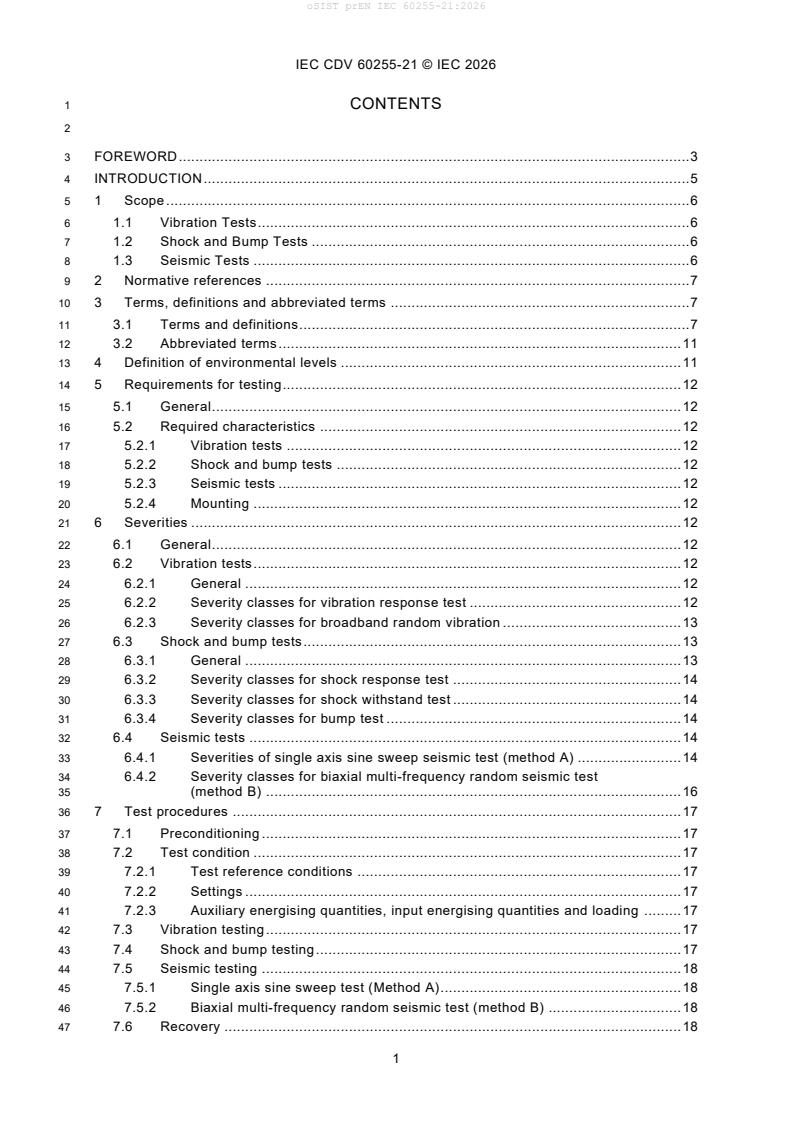
oSIST prEN IEC 60255-21:2026 is a SIST Slovenian standard identical to prEN IEC 60255-21:2026, published for measuring relays and protection equipment. It specifies vibration, shock, bump and seismic tests for equipment used in power-system protection, so manufacturers, test laboratories and buyers can verify how the equipment behaves during transport, handling, installation and service.
What does oSIST prEN IEC 60255-21:2026 specify?
oSIST prEN IEC 60255-21:2026 specifies withstand levels and associated test methods for vibration response, broadband random vibration, shock response, shock withstand, bump and seismic testing. It applies to measuring relays and protection equipment in the condition in which new equipment is supplied by the manufacturer.
The document is organized into clauses 1 to 9, plus a bibliography. Clause 1 states the scope and the test types, Clause 2 lists the normative references, Clause 3 defines the terms, Clause 4 sets environmental levels, Clauses 5 to 8 cover test requirements, severities, procedures and acceptance criteria, and Clause 9 defines the test report content.
What are the key requirements of oSIST prEN IEC 60255-21:2026?
oSIST prEN IEC 60255-21:2026 requires the equipment under test to pass all tests in the document to claim compliance. It also requires pre-checks and post-checks in accordance with IEC 60255-1, and the test order may be changed if needed to reduce test time.
Environmental class selection and mounting
Clause 4 ties the test level to the expected installation environment. Class 1 represents typical indoor industrial and power-system locations such as process equipment rooms, power plants and relay rooms in substations, while Class 2 represents more severe outdoor locations such as switchyards and gas insulated switchgear. In practice, this means the selected severity should match how the equipment will really be installed and transported.
Clause 5.2.4 requires the equipment to be mounted on a rigid fixture that reflects the manufacturer’s recommended mounting arrangement. The fixing method, bolt size and torque come from the technical documentation, the cable connections must represent normal service, and magnetic fields from the vibration system must not significantly affect the equipment. This matters because the mounting arrangement can change the test result as much as the test level itself.
Vibration tests
Clause 1.1 and Clause 6 divide vibration testing into a vibration response test on energised equipment and a broadband random vibration test on non-energised equipment. The document uses two severity classes, and the selected class depends on the expected environment and the product declaration. In practice, the reader must choose the right class and then test in the three mutually perpendicular axes.
For the vibration response test, Clause 6.2 uses a frequency range from 10 Hz to 150 Hz and defines severity by frequency range, amplitude and duration. For broadband random vibration, Clause 6.2.3 uses 5 Hz to 150 Hz and a random acceleration spectral density profile. The document also points to IEC 60068-2-6 and IEC 60068-2-64 for the test methods.
Shock and bump tests
Clause 1.2 and Clause 6.3 split shock and bump testing into three cases: shock response on energised equipment, shock withstand on non-energised equipment, and bump testing on non-energised equipment. The severity is defined by peak acceleration, pulse duration and the number of pulses. For the reader, this means the equipment must be checked both while operating and while stored or transported.
Clause 5.2.2 says the shock and bump system uses a half-sine pulse shape, in line with IEC 60068-2-27. Clause 6.3 also states that the test uses severity classes 1 and 2, with the values chosen so that the classes can be compared directly.
Seismic tests
Clause 1.3 gives two acceptable seismic methods: the single axis sine sweep seismic test, called method A, and the biaxial multi-frequency random seismic test, called method B. Neither method is identified as the reference method. This matters because a user can specify either method, depending on the qualification approach and the available test equipment.
Clause 6.4 says method A uses a defined frequency range, acceleration above the crossover frequency, displacement below it, sweep rate and number of sweep cycles. Method B uses a standard response spectrum, zero-period acceleration, damping ratio, number and duration of time histories, and biaxial application. Clause 6.4.2 also states a damping ratio of 5 % and requires a pause between time histories so the equipment response does not overlap significantly.
Test execution, checks and acceptance
Clause 7 requires testing in three orthogonal axes, with binary output ports monitored during vibration response, shock response and seismic tests. For method B, the two time histories are applied simultaneously on the preferred testing axes, and if they are not independent the test is repeated with phase angles of 0° and 180°. Final measurements include visual, functional, insulation resistance and dielectric testing in accordance with IEC 60255-1.
Clause 8 sets the acceptance criteria. For vibration response, shock response, broadband random vibration and seismic tests, the equipment must not maloperate, and its indicators or displays must not change state permanently. For shock withstand and bump tests, the equipment must not suffer mechanical damage and must still pass insulation resistance and dielectric withstand checks after testing.
What terms does oSIST prEN IEC 60255-21:2026 define?
- Acceleration spectral density (ASD) - a measure used in broadband random vibration to describe the vibration level across frequency.
- Damping ratio (DR) - the ratio of actual viscous damping to critical damping, usually expressed as a percentage.
- Zero-period acceleration (ZPA) - the peak acceleration value used in the seismic response spectrum context.
- Response spectrum - a plot showing the maximum response of single-degree-of-freedom bodies versus natural frequency at a specified damping ratio.
- Reference point - the checkpoint signal used to control the test so the document’s requirements are met.
- Shock severity - the combination of peak acceleration, pulse duration and number of shocks.
- Preferred testing axes - the three orthogonal axes that correspond to the most vulnerable axes of the equipment.
Who uses oSIST prEN IEC 60255-21:2026?
oSIST prEN IEC 60255-21:2026 is used by manufacturers of measuring relays and protection equipment, test laboratories, and quality or verification teams that qualify equipment for power-system service. It is also used by buyers and specifiers who need to confirm transport, handling and seismic robustness before acceptance.
The document is especially relevant for equipment installed near electrical installations such as power stations, substations and industrial buildings. It also addresses equipment mounted in racks, panels or cubicles, which is common in relay rooms and switchgear installations.
What changed in oSIST prEN IEC 60255-21:2026 from the previous edition?
oSIST prEN IEC 60255-21:2026 cancels and replaces IEC 60255-21-1:1988, IEC 60255-21-2:1988 and IEC 60255-21-3:1993. It is described as a technical revision.
The document states these main changes:
- the three IEC 60255-21 documents were merged into one mechanical standard;
- unused terms were removed from the terminology;
- duplicated parameters were replaced by references to the base standards;
- settings and pre-testing and post-testing are referenced to IEC 60255-1;
- vibration endurance using a sinusoidal sweep was removed;
- random vibration tests were added;
- transportation tests were clarified for equipment mounted in panels or cubicles.
Which standards are used with oSIST prEN IEC 60255-21:2026?
oSIST prEN IEC 60255-21:2026 uses several IEC environmental test standards to define the test methods and mounting arrangements.
- IEC 60068-2-6 - provides vibration testing by sinusoidal motion and the Fc test method.
- IEC 60068-2-27 - provides shock testing and the Ea method.
- IEC 60068-2-47 - gives mounting guidance for vibration, impact and similar dynamic tests.
- IEC 60068-2-57 - provides the Ff vibration and seismic method used for method B.
- IEC 60068-2-64 - provides broadband random vibration testing and guidance.
- IEC 60255-1 - provides common requirements, reference conditions, settings, and the post-test checks used throughout this document.
What does the oSIST prEN IEC 60255-21:2026 document contain?
The document contains tables for environmental classes, vibration severities, shock severities, bump severities and seismic severities. It also includes figures for the standard response spectrum, frequency break points and seismic acceleration-versus-frequency behavior.
Clauses 7 and 8 describe the test sequence, preconditioning, energised and non-energised test conditions, monitoring of binary outputs, recovery, final measurements and acceptance criteria. Clause 9 specifies what the test report should record, including fixture identification, excitation axis, sensor location, filters, uncertainty, control strategy, measurements, results and observations.
The document is designed for type testing and qualification work. In practice, it gives the test engineer the setup, severity selection, execution method and reporting items needed to demonstrate mechanical robustness under vibration, shock, bump and seismic conditions.
Relations
- Effective Date
- 16-Jun-2026
- Effective Date
- 16-Jun-2026
- Effective Date
- 16-Jun-2026
Get Certified
Connect with accredited certification bodies for this standard

IMQ S.p.A. (Certification)
Italian electrical product certification.

SLG Prüf- und Zertifizierungs GmbH
German testing and certification body.

UL Solutions
Global safety science company with testing, inspection and certification.
Sponsored listings
Frequently Asked Questions
oSIST prEN IEC 60255-21:2026 is a draft published by the Slovenian Institute for Standardization (SIST). Its full title is "Measuring relays and protection equipment - Part 21: Vibration, shock, bump and seismic tests requirements". This standard covers: Measuring relays and protection equipment - Part 21: Vibration, shock, bump and seismic tests requirements
Measuring relays and protection equipment - Part 21: Vibration, shock, bump and seismic tests requirements
oSIST prEN IEC 60255-21:2026 is classified under the following ICS (International Classification for Standards) categories: 29.120.70 - Relays. The ICS classification helps identify the subject area and facilitates finding related standards.
oSIST prEN IEC 60255-21:2026 has the following relationships with other standards: It is inter standard links to SIST EN 60255-21-1:2001, SIST EN 60255-21-3:2001, SIST EN 60255-21-2:2001. Understanding these relationships helps ensure you are using the most current and applicable version of the standard.
oSIST prEN IEC 60255-21:2026 is available in PDF format for immediate download after purchase. The document can be added to your cart and obtained through the secure checkout process. Digital delivery ensures instant access to the complete standard document.
Standards Content (Sample)
SLOVENSKI STANDARD
01-november-2026
Merilni releji in zaščitna oprema - 21. del: Zahteve za preskuse vibracij, udarcev,
sunkov in potresov
Measuring relays and protection equipment - Part 21: Vibration, shock, bump and
seismic tests requirements
Relais de mesure et équipements de protection - Partie 21: Exigences pour les essais de
vibrations, de chocs, de secousses et sismiques
Ta slovenski standard je istoveten z: prEN IEC 60255-21:2026
ICS:
29.120.70 Releji Relays
2003-01.Slovenski inštitut za standardizacijo. Razmnoževanje celote ali delov tega standarda ni dovoljeno.
95/647/CDV
COMMITTEE DRAFT FOR VOTE (CDV)
PROJECT NUMBER:
IEC 60255-21 ED1
DATE OF CIRCULATION: CLOSING DATE FOR VOTING:
2026-09-11 2026-12-04
SUPERSEDES DOCUMENTS:
95/586A/CD, 95/605A/CC
IEC TC 95 : MEASURING RELAYS AND PROTECTION EQUIPMENT
SECRETARIAT: SECRETARY:
France Mr Thierry BARDOU
OF INTEREST TO THE FOLLOWING COMMITTEES: HORIZONTAL FUNCTION(S):
TC 17,TC 38
ASPECTS CONCERNED:
Electricity transmission and distribution
SUBMITTED FOR CENELEC PARALLEL VOTING NOT SUBMITTED FOR CENELEC PARALLEL VOTING
Attention IEC-CENELEC parallel voting
The attention of IEC National Committees, members of
CENELEC, is drawn to the fact that this Committee Draft
for Vote (CDV) is submitted for parallel voting.
The CENELEC members are invited to vote through the
CENELEC online voting system.
This document is still under study and subject to change. It should not be used for reference purposes.
Recipients of this document are invited to submit, with their comments, notification of any relevant patent rights of
which they are aware and to provide supporting documentation.
Recipients of this document are invited to submit, with their comments, notification of any relevant “In Some
Countries” clauses to be included should this proposal proceed. Recipients are reminded that the CDV stage is
the final stage for submitting ISC clauses. (SEE AC/22/2007 OR NEW GUIDANCE DOC).
TITLE:
Measuring relays and protection equipment - Part 21: Vibration, shock, bump and seismic tests
requirements
PROPOSED STABILITY DATE: 2032
NOTE FROM TC/SC OFFICERS:
download this electronic file, to make a copy and to print out the content for the sole purpose of preparing National
Committee positions. You may not copy or "mirror" the file or printed version of the document, o r any part of it,
for any other purpose without permission in writing from IEC.
IEC CDV 60255-21 © IEC 2026
1 CONTENTS
3 FOREWORD . 3
4 INTRODUCTION . 5
5 1 Scope . 6
6 1.1 Vibration Tests . 6
7 1.2 Shock and Bump Tests . 6
8 1.3 Seismic Tests . 6
9 2 Normative references . 7
10 3 Terms, definitions and abbreviated terms . 7
11 3.1 Terms and definitions . 7
12 3.2 Abbreviated terms . 11
13 4 Definition of environmental levels . 11
14 5 Requirements for testing . 12
15 5.1 General . 12
16 5.2 Required characteristics . 12
17 5.2.1 Vibration tests . 12
18 5.2.2 Shock and bump tests . 12
19 5.2.3 Seismic tests . 12
20 5.2.4 Mounting . 12
21 6 Severities . 12
22 6.1 General . 12
23 6.2 Vibration tests . 12
24 6.2.1 General . 12
25 6.2.2 Severity classes for vibration response test . 12
26 6.2.3 Severity classes for broadband random vibration . 13
27 6.3 Shock and bump tests . 13
28 6.3.1 General . 13
29 6.3.2 Severity classes for shock response test . 14
30 6.3.3 Severity classes for shock withstand test . 14
31 6.3.4 Severity classes for bump test . 14
32 6.4 Seismic tests . 14
33 6.4.1 Severities of single axis sine sweep seismic test (method A) . 14
34 6.4.2 Severity classes for biaxial multi-frequency random seismic test
35 (method B) . 16
36 7 Test procedures . 17
37 7.1 Preconditioning . 17
38 7.2 Test condition . 17
39 7.2.1 Test reference conditions . 17
40 7.2.2 Settings . 17
41 7.2.3 Auxiliary energising quantities, input energising quantities and loading . 17
42 7.3 Vibration testing . 17
43 7.4 Shock and bump testing . 17
44 7.5 Seismic testing . 18
45 7.5.1 Single axis sine sweep test (Method A). 18
46 7.5.2 Biaxial multi-frequency random seismic test (method B) . 18
47 7.6 Recovery . 18
IEC CDV 60255-21 © IEC 2026
48 7.7 Final measurements . 18
49 8 Acceptance criteria . 18
50 8.1 Acceptance criteria for vibration response, shock response random
51 broadband vibration and seismic test . 18
52 8.2 Acceptance criteria for shock withstand and bump test . 18
53 9 Test report . 18
54 Bibliography . 20
56 Table 1 – Environmental classes . 11
57 Table 2 – Vibration response test parameters for different severity classes . 13
58 Table 3 – Break points for spectrum – for different severity classes . 13
59 Table 4 – Shock response test parameters for different severity classes . 14
60 Table 5 – Shock withstand test parameters for different severity classes . 14
61 Table 6 – Bump test parameters for different severity classes . 14
62 Table 7 – Single axis sine sweep seismic test parameters for different severity classes . 15
63 Table 8 – Biaxial multi-frequency random seismic test parameters for different severity
64 classes . 17
66 Figure 1 – Multi-frequency broad-band standard response spectrum shape . 10
67 Figure 2 – Frequency / amplitude break points . 13
68 Figure 3 – Acceleration versus frequency for the single axis sine sweep seismic test . 16
IEC CDV 60255-21 © IEC 2026
71 INTERNATIONAL ELECTROTECHNICAL COMMISSION
72 ____________
74 MEASURING RELAYS AND PROTECTION EQUIPMENT –
76 Part 21: Vibration, shock, bump and seismic test requirements
78 FOREWORD
79 1) The International Electrotechnical Commission (IEC) is a worldwide organization for standardization comprising
80 all national electrotechnical committees (IEC National Committees). The object of IEC is to promote international
81 co-operation on all questions concerning standardization in the electrical and electronic fields. To this end and
82 in addition to other activities, IEC publishes International Standards, Technical Specifications, Technical Reports,
83 Publicly Available Specifications (PAS) and Guides (hereafter referred to as “IEC Publication(s)”). Their
84 preparation is entrusted to technical committees; any IEC National Committee interested in the subject dealt with
85 may participate in this preparatory work. International, governmental and non-governmental organizations liaising
86 with the IEC also participate in this preparation. IEC collaborates closely with the International Organization for
87 Standardization (ISO) in accordance with conditions determined by agreement between the two organizations.
88 2) The formal decisions or agreements of IEC on technical matters express, as nearly as possible, an international
89 consensus of opinion on the relevant subjects since each technical committee has representation from all
90 interested IEC National Committees.
91 3) IEC Publications have the form of recommendations for international use and are accepted by IEC National
92 Committees in that sense. While all reasonable efforts are made to ensure that the technical content of IEC
93 Publications is accurate, IEC cannot be held responsible for the way in which they are used or for any
94 misinterpretation by any end user.
95 4) In order to promote international uniformity, IEC National Committees undertake to apply IEC Publications
96 transparently to the maximum extent possible in their national and regional publications. Any divergence between
97 any IEC Publication and the corresponding national or regional publication shall be clearly indicated in the latter.
98 5) IEC itself does not provide any attestation of conformity. Independent certification bodies provide conformity
99 assessment services and, in some areas, access to IEC marks of conformity. IEC is not responsible for any
100 services carried out by independent certification bodies.
101 6) All users should ensure that they have the latest edition of this publication.
102 7) No liability shall attach to IEC or its directors, employees, servants or agents including individual experts and
103 members of its technical committees and IEC National Committees for any personal injury, property damage or
104 other damage of any nature whatsoever, whether direct or indirect, or for costs (including legal fees) and
105 expenses arising out of the publication, use of, or reliance upon, this IEC Publication or any other IEC Publications.
106 8) Attention is drawn to the Normative references cited in this publication. Use of the referenced publications is
107 indispensable for the correct application of this publication.
108 9) Attention is drawn to the possibility that some of the elements of this IEC Publication may be the subject of patent
109 rights. IEC shall not be held responsible for identifying any or all such patent rights.
110 International Document IEC 60255-21 has been prepared by IEC technical committee 95:
111 Measuring relays and protection equipment.
112 This document cancels and replace the documents IEC 60255-21-1:1988, IEC 60255-21-2:
113 1988 and IEC 60255-21-3:1993. This document constitutes a technical revision.
114 This document includes the following significant technical changes with respect to the
115 documents IEC 60255-21-1: 1998, IEC 60255-21-2: 1988 and IEC 60255-21-3: 1993:
116 a) The three IEC 60255-21 standards have been merged into a single mechanical standard;
117 b) terminology updated to remove unused terms;
118 c) duplication of parameters from the base standards have been removed replaced with references to
119 the base standards;
120 d) references have been included for settings and for pre testing and post testing in accordance with
121 IEC 60255-1;
122 e) vibration endurance using a sinusoidal sweep has been removed
123 f) random vibration tests have been added;
124 g) transportation tests have been clarified that they are for equipment mounted in panels or cubicles.
125 The text of this International Document is based on the following documents:
IEC CDV 60255-21 © IEC 2026
FDIS Report on voting
95/XX/FDIS 95/XX/RVD
127 Full information on the voting for the approval of this International Document can be found in
128 the report on voting indicated in the above table.
129 This document has been drafted in accordance with the ISO/IEC Directives, Part 2.
130 The committee has decided that the contents of this document will remain unchanged until the
131 stability date indicated on the IEC website under "http://webstore.iec.ch" in the data related to
132 the specific document. At this date, the document will be
133 • reconfirmed,
134 • withdrawn,
135 • replaced by a revised edition, or
136 • amended.
IEC CDV 60255-21 © IEC 2026
137 INTRODUCTION
138 This part of IEC 60255 specifies tests applicable to measuring relays or protection equipment
139 that are expected to experience various vibration, shock, bump, and seismic environments
140 during transportation, handling, storage, or in service.
141 The main part of this document provides, in detail, the procedure for each test. For vibration
142 and seismic tests, the requirements for the vibration motion, choice of severities including
143 frequency ranges, amplitudes, endurance times, and response spectrum are also specified. In
144 the case of shock and bump tests, the requirements for the test, choice of severities including
145 acceleration, duration of the nominal pulse, and number of pulses are defined herein. In each
146 case, each selected severity level is represented by a series of parameters.
147 VIBRATION TESTS
148 This portion of the document defines tests intended to emulate conditions involving vibration of
149 a harmonic pattern. Such vibration environments are generated primarily by rotating, pulsating,
150 or oscillating forces. These are essentially caused by machinery.
151 SHOCK AND BUMP TESTS
152 This portion of the document defines tests intended to emulate conditions involving relatively
153 infrequent, non-repetitive or repetitive shocks e.g. circuit breaker operation.
154 SEISMIC TESTS
155 This portion of the document defines tests intended to emulate random or oscillating dynamic
156 forces for short duration that are induced in equipment as a result of earthquakes . The
157 characteristics of these forces and the damping of the equipment could be such that the
158 vibration response of the equipment will not reach a steady-state condition.
IEC CDV 60255-21 © IEC 2026
159 MEASURING RELAYS AND PROTECTION EQUIPMENT –
161 Part 21: Vibration, shock, bump and seismic tests
165 1 Scope
166 This part of IEC 60255 specifies the withstand levels and associated tests for vibration response,
167 broadband random vibration, shock response, shock withstand, bump, and seismic tests
168 applicable to measuring relays and protection equipment. The purpose of these tests is to prove
169 the capability of a measuring relay or protection equipment to withstand conditions of vibration,
170 shocks, and bumps encountered in service, during transportation unpackaged in final
171 arrangement e.g. relays mounted in cubicle. They also demonstrate the capability of a
172 measuring relay or protection equipment to perform its required function during and after the
173 time it is subjected to the stresses and displacements resulting from an earthquake . To claim
174 compliance a product shall meet all tests specified in this document.
175 All measuring relays and protection equipment used for protection within the power system
176 environment are covered by this document. Other documents in this series can define their own
177 requirements which in such cases take precedence. The measuring relays and protection
178 equipment are generally located close to the electrical installations to be protected : power
179 stations, substation, and industrial buildings.
180 Measuring relays and protection equipment installed in special applications (marine, railways,
181 aerospace, explosive atmospheres, computer centres, etc.) could have additional requirements
182 required by that application.
183 The requirements specified in this document are applicable to measuring relays and protection
184 equipment in a condition representative of how new equipment is provided by the manufacturer.
185 All tests in this document are type tests, unless otherwise declared. As each category of test
186 has a unique procedure and requirements, the below details are also provided.
187 1.1 Vibration Tests
188 This document includes two types of vibration test: the vibration response test on energised
189 equipment under test, carried out in accordance with test Fc of IEC 60068-2-6. and the
190 broadband random vibration test on non-energised equipment under test, carried out in
191 accordance with IEC 60068-2-64.
192 1.2 Shock and Bump Tests
193 This document includes three types of tests: the shock response test on energised equipment
194 under test, the shock withstand test on non-energised equipment under test, and the bump test
195 on non-energised equipment under test, carried out in accordance with test Ea of IEC 60068-
196 2-27. However, some test parameters included herein are not exactly the same as those found
197 in IEC 60068-2-27. This is because the values of test parameters in this document have been
198 selected to always allow a direct comparison between severity levels (Class 1 and 2).
199 1.3 Seismic Tests
200 This document includes two alternative types of seismic test:
201 • the single axis sine sweep seismic test (method A); and
202 • the biaxial multi-frequency random seismic test (method B).
203 Both methods are acceptable, and neither has been identified as reference (or referee) method.
204 The tests are carried out in accordance with test Fc of IEC 60068-2-6 (method A) and the test
205 Ff of IEC 60068-2-57 (method B).
IEC CDV 60255-21 © IEC 2026
206 2 Normative references
207 The following documents are referred to in the text in such a way that some or all of their content
208 constitutes requirements of this document. For dated references, only the edition cited applies.
209 For undated references, the latest edition of the referenced document (including any
210 amendments) applies.
211 IEC 60068-2-6:2007 Environmental testing - Part 2-6: Tests - Test Fc: Vibration (sinusoidal)
212 IEC 60068-2-27:2008 Environmental testing - Part 2-27: Tests - Test Ea and guidance: Shock
213 IEC 60068-2-47:2005 Environmental testing - Part 2-47: Test - Mounting of specimens for
214 vibration, impact and similar dynamic tests
215 IEC 60068-2-57:2013 Environmental testing - Part 2-57: Tests - Test Ff: Vibration - Time-history
216 and sine-beat method
217 IEC 60068-2-64:2008+AMD1:2019 CSV Environmental testing - Part 2-64: Tests – Test Fh:
218 Vibration, broadband random and guidance
219 IEC 60255-1:2022 Measuring relays and protection equipment - Part 1: Common requirements
220 3 Terms, definitions and abbreviated terms
221 3.1 Terms and definitions
222 For the purposes of this document, the following terms and definitions apply.
223 ISO and IEC maintain terminological databases for use in standardization at the following
224 addresses:
225 • IEC Electropedia: available at http://www.electropedia.org/
226 • ISO Online browsing platform: available at http://www.iso.org/obp
228 3.1.1
229 biaxial multi-frequency random seismic test
230 a test during which an equipment is submitted to a random sequence of stresses with a test
231 response spectrum which reproduces the standard response spectrum by a biaxial multi -
232 frequency input motion
233 3.1.2
234 biaxial testing
235 a test during which an equipment is submitted to stresses in the horizontal and vertical axes
236 simultaneously
237 3.1.3
238 bump test
239 a test during which a non-energised measuring relay or protection equipment is subjected to a
240 limited number of bumps, in three different axes of the equipment in turn, to determine its
241 capability to withstand the effects of bumps likely to be encountered during transportation
242 3.1.4
243 check point
244 point located on the fixture, on the table surface of the shock-testing machine or on the
245 specimen as close as possible to the fixing point, and in any case rigidly connected to it
246 Note 1 to entry: A number of check points are used as a means of ensuring that the test requirements are satisfied.
247 Note 2 to entry: If more than four fixing points exist, the relevant specification should state the number of fixing
248 points to be used as checkpoints.
249 Note 3 to entry: In special cases, for example, for large or complex specimens, the check points will be prescribed
250 by the relevant specification if not close to the fixing points.
251 Note 4 to entry: Where a large number of small specimens are mounted on one fixture, or in the case of a small
252 specimen where there are a number of fixing points, a single checkpoint (that is the reference point) may be selected
...