

SIST EN IEC 61810-7-19:2026
(Main)Electrical relays - Tests and Measurements - Part 7-19: Electrical endurance
- Status
- Not Published
- Public Enquiry End Date
- 31-Oct-2023
- Technical Committee
- ISS EIT.ERE - All-or-nothing electrical relays
- Current Stage
- 6060 - National Implementation/Publication (Adopted Project)
- Start Date
- 15-Oct-2026
- Due Date
- 20-Dec-2026

SIST EN IEC 61810-7-19:2026 is the Slovenian standard for Electrical relays - Tests and Measurements - Part 7-19: Electrical endurance, published by SIST and aligned with IEC 61810-7-19. It specifies how to test relay electrical endurance under normal, overload, inductive, lamp, cable, inrush, and special-load conditions, and how to evaluate the result. It is intended for relay manufacturers, test laboratories, quality teams, and anyone qualifying relays for switching applications.
What does SIST EN IEC 61810-7-19:2026 specify?
SIST EN IEC 61810-7-19:2026 gives guidance for testing relay performance under expected transportation, storage, and operational conditions, with the focus on electrical endurance. Clause 1 states that the document is used with appropriate severities and conditions to assess how specimens perform in service.
The document is organised into five main clauses and three annexes:
- Clause 1 Scope
- Clause 2 Normative references
- Clause 3 Terms and definitions
- Clause 4 Test procedure
- Clause 5 Evaluation
- Annex A Special loads
- Annex B Inductive contact loads
- Annex T Test report
The Slovenian standard is identical to prEN IEC 61810-7-19:2023.
| Annex | What it covers |
|---|---|
| Annex A | Special loads, including dedicated device applications, motor starting, lamp loads, cable loads, inrush current loads, electronic ballast loads, and solid-state relay tests |
| Annex B | Inductive contact loads, with utilization categories and test values corresponding to IEC 60947-5-1 |
| Annex T | The test report content needed to document the test |
What are the key requirements of SIST EN IEC 61810-7-19:2026?
The core of SIST EN IEC 61810-7-19:2026 is the test procedure in Clause 4, which tells you how to set up the relay, load it, run the endurance sequence, and judge the result. In practice, this is the part that determines whether a relay design can survive the expected switching duty.
Test setup and sampling
Clause 4.2 says the test is carried out on each contact load and each contact material specified by the manufacturer. Table 1 gives the number of samples and mounting conditions for type test and sampling test. That matters because the same relay can behave differently depending on how it is mounted and which contact system is being assessed.
The preferred mounting is group mounting for the endurance sequence, unless the manufacturer specifies otherwise. For PCB relays, a PCB may be used for wiring if minimum mounting distances are maintained. The document also says the load circuit shall follow the annexed test circuit unless the manufacturer explicitly specifies a different one.
Severity levels and operating duty
Clause 4.2 defines three severity levels. Severity A treats the first malfunction as a failure, Severity B allows more malfunctions before failure is declared, and Severity C follows the manufacturer’s declared level. This gives the test user a way to match the test to the intended application risk.
Unless the manufacturer states otherwise, the endurance test is done at the upper limit of the ambient temperature range, with the relay coil energized at rated voltage or another value within the rated coil voltage or operative range. If no other value is specified, the operating rate is 360 operations per hour with duty type S6 50% and 6000 operations total. The test frequency must stay below the relay’s maximum frequency of operation from IEC 61810-7-45.
Monitoring and functional checks
Clause 4 requires the contacts to be monitored for failure to make, failure to break, and unintended bridging. For relays with a manual actuating member, the document adds a manual-operation check at least 100 times, using the maximum rated switching current at the related voltage unless the manufacturer specifies otherwise. That is important for products that may be operated both automatically and by hand.
Clause 4.3 lists the conditions that have to be stated for the test, including relay type, contact material, severity level, ambient conditions, mounting method, energization value, switching current, power factor or time constant, duty factor, protective devices, and final measurements. The final measurements may include the dielectric strength test from IEC 61810-7-4 and any other checks specified by the manufacturer.
Overload testing
Clause 4 includes an overload test for fault conditions when the manufacturer declares limiting making or breaking capacity above the rated switching current. The test uses 50 cycles for AC and DC loads unless otherwise specified, and the relay must show no malfunction. After overload testing, the same samples are used for endurance testing under the same conditions.
For DC loads, the contacts should switch at least twice their maximum rated current at maximum rated voltage unless otherwise specified. For AC loads, the contacts should switch at least twice their maximum rated current at rated voltage. The clause also notes that special loads are treated in Annex A and inductive loads in Annex B.
Evaluation after testing
Clause 5 says the relay fails if the applicable failure criterion is not met. After the electrical endurance procedure, the dielectric strength test is performed again, and contact-circuit resistance and functional tests are measured when applicable. A final visual inspection is also required to verify electrical integrity.
What terms does SIST EN IEC 61810-7-19:2026 define?
Making and breaking capacities - the greatest current a relay output circuit can make and break under specified conditions such as voltage, number of operations, power factor, and time constant.
Overload - operating conditions in an electrically undamaged circuit that cause an overcurrent. In practice, this is the fault-duty condition used to stress the relay beyond normal operation.
Utilization category - a combination of requirements that represents a characteristic group of practical applications. In this document, it helps relate relay tests to real switching duties.
Severity level - the failure criterion used in the endurance test. Severity A fails on the first malfunction, Severity B on the sixth detected malfunction or two consecutive malfunctions, and Severity C is manufacturer-defined.
Contact-circuit resistance - the resistance of the contact circuit measured after testing where applicable. It shows whether the contact path has degraded.
Who uses SIST EN IEC 61810-7-19:2026?
SIST EN IEC 61810-7-19:2026 is used by relay manufacturers, test laboratories, certification and conformity assessment bodies, and quality assurance teams. It is also relevant to buyers and engineers who need to specify endurance testing for relays used in control circuits, motor starting, lamp switching, telecom and signalling applications, and other switching duties.
The document is especially useful when relays are intended for special loads, inductive loads, inrush current loads, or high-capacity applications. It also supports users who need to document test conditions and results in a reproducible way.
What changed in SIST EN IEC 61810-7-19:2026 from the previous edition?
This document supersedes 94/851/CD and 94/913/CC. The source states that it is still under study and subject to change at the draft stage.
Which standards are used with SIST EN IEC 61810-7-19:2026?
SIST EN IEC 61810-7-19:2026 is to be used with IEC 61810-1:2015. That relationship matters because the endurance part relies on the general relay requirements in the base standard.
The normative references and companion parts named in the document are:
- IEC 60669-1:2017 - provides household and similar fixed-electrical installation requirements used in some load and application cases.
- IEC 60947-5-1:2016 - provides utilization categories and test values referenced in Annex B.
- IEC 61810-7-0:202X - provides the general testing and guidance framework used throughout the document.
- IEC 61810-7-4:202X - provides the dielectric strength test used after endurance testing.
- IEC 61810-7-6:202X - provides contact-circuit resistance or voltage drop measurement.
- IEC 61810-7-7:202X - provides functional tests used in evaluation.
- IEC 61810-7-45:202X - provides the maximum frequency of operation.
- IEC 61810-10:2019 - provides additional functional aspects and safety requirements for high-capacity relays.
- IEC 62246-1:2015 - provides the generic specification for reed switches.
What does the SIST EN IEC 61810-7-19:2026 document contain?
The document contains the test procedures, test circuits, and reporting structure needed to assess relay electrical endurance. Table 1 sets sample numbers and mounting conditions, Table 2 sets the test procedure flow, and Table 3 gives schematics for contact loading. Those tables are the practical core for planning a lab test or writing a specification.
Annex A adds detailed procedures and figures for special loads such as motor starting, resistance loads, lamp loads, cable loads, electronic ballast loads, and solid-state relay testing. It includes multiple test values tables and circuit figures so that the test lab can build the correct load and verify inrush and endurance behaviour.
Annex B provides the inductive-load test matrix, including normal and abnormal conditions, endurance testing, and contact rating equivalencies to utilization categories. Annex T defines what the test report has to record so that the test can be reproduced and reviewed later.
Relations
- Refers
SIST EN IEC 61810-7:2025 - Electrical relays - Tests and Measurements - Part 7: Functional Tests - Effective Date
- 15-Sep-2026
- Effective Date
- 15-Sep-2026
- Effective Date
- 15-Sep-2026
- Effective Date
- 15-Sep-2026
- Effective Date
- 15-Sep-2026
- Effective Date
- 15-Sep-2026
- Effective Date
- 15-Sep-2026
- Effective Date
- 15-Sep-2026
- Effective Date
- 03-Feb-2026
Get Certified
Connect with accredited certification bodies for this standard

IMQ S.p.A. (Certification)
Italian electrical product certification.

SLG Prüf- und Zertifizierungs GmbH
German testing and certification body.

UL Solutions
Global safety science company with testing, inspection and certification.
Sponsored listings
Frequently Asked Questions
SIST EN IEC 61810-7-19:2026 is a draft published by the Slovenian Institute for Standardization (SIST). Its full title is "Electrical relays - Tests and Measurements - Part 7-19: Electrical endurance". This standard covers: Electrical relays - Tests and Measurements - Part 7-19: Electrical endurance
Electrical relays - Tests and Measurements - Part 7-19: Electrical endurance
SIST EN IEC 61810-7-19:2026 is classified under the following ICS (International Classification for Standards) categories: 29.120.70 - Relays. The ICS classification helps identify the subject area and facilitates finding related standards.
SIST EN IEC 61810-7-19:2026 has the following relationships with other standards: It is inter standard links to SIST EN IEC 61810-7:2025, SIST EN IEC 63522-41:2026, kSIST FprEN IEC 63522-0:2026, SIST EN IEC 63522-6:2025, SIST EN IEC 63522-4:2026, SIST EN IEC 61810-10:2021, SIST EN IEC 61810-45:2025, SIST EN IEC 60947-5-1:2025, SIST EN IEC 63522-11:2025. Understanding these relationships helps ensure you are using the most current and applicable version of the standard.
SIST EN IEC 61810-7-19:2026 is available in PDF format for immediate download after purchase. The document can be added to your cart and obtained through the secure checkout process. Digital delivery ensures instant access to the complete standard document.
Standards Content (Sample)
SLOVENSKI STANDARD
oSIST prEN IEC 61810-7-19:2023
01-oktober-2023
Električni releji - Preskusi in meritve - 7-19. del: Električna življenjska doba
Electrical relays - Tests and Measurements - Part 7-19: Electrical endurance
Ta slovenski standard je istoveten z: prEN IEC 61810-7-19:2023
ICS:
29.120.70 Releji Relays
oSIST prEN IEC 61810-7-19:2023 en
2003-01.Slovenski inštitut za standardizacijo. Razmnoževanje celote ali delov tega standarda ni dovoljeno.
oSIST prEN IEC 61810-7-19:2023
oSIST prEN IEC 61810-7-19:2023
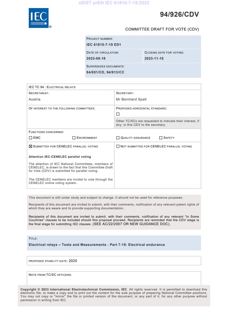
94/926/CDV
COMMITTEE DRAFT FOR VOTE (CDV)
PROJECT NUMBER:
IEC 61810-7-19 ED1
DATE OF CIRCULATION: CLOSING DATE FOR VOTING:
2023-08-18 2023-11-10
SUPERSEDES DOCUMENTS:
94/851/CD, 94/913/CC
IEC TC 94 : ELECTRICAL RELAYS
SECRETARIAT: SECRETARY:
Austria Mr Bernhard Spalt
OF INTEREST TO THE FOLLOWING COMMITTEES: PROPOSED HORIZONTAL STANDARD:
Other TC/SCs are requested to indicate their interest, if
any, in this CDV to the secretary.
FUNCTIONS CONCERNED:
EMC ENVIRONMENT QUALITY ASSURANCE SAFETY
SUBMITTED FOR CENELEC PARALLEL VOTING NOT SUBMITTED FOR CENELEC PARALLEL VOTING
Attention IEC-CENELEC parallel voting
The attention of IEC National Committees, members of
CENELEC, is drawn to the fact that this Committee Draft
for Vote (CDV) is submitted for parallel voting.
The CENELEC members are invited to vote through the
CENELEC online voting system.
This document is still under study and subject to change. It should not be used for reference purposes.
Recipients of this document are invited to submit, with their comments, notification of any relevant patent rights of
which they are aware and to provide supporting documentation.
Recipients of this document are invited to submit, with their comments, notification of any relevant “In Some
Countries” clauses to be included should this proposal proceed. Recipients are reminded that the CDV stage is
the final stage for submitting ISC clauses. (SEE AC/22/2007 OR NEW GUIDANCE DOC).
TITLE:
Electrical relays – Tests and Measurements - Part 7-19: Electrical endurance
PROPOSED STABILITY DATE: 2025
NOTE FROM TC/SC OFFICERS:
electronic file, to make a copy and to print out the content for the sole purpose of preparing National Committee positions.
You may not copy or "mirror" the file or printed version of the document, or any part of it, for any other purpose without
permission in writing from IEC.
oSIST prEN IEC 61810-7-19:2023
– 2 – IEC CDV 61810-7-19:2023 © IEC 2023
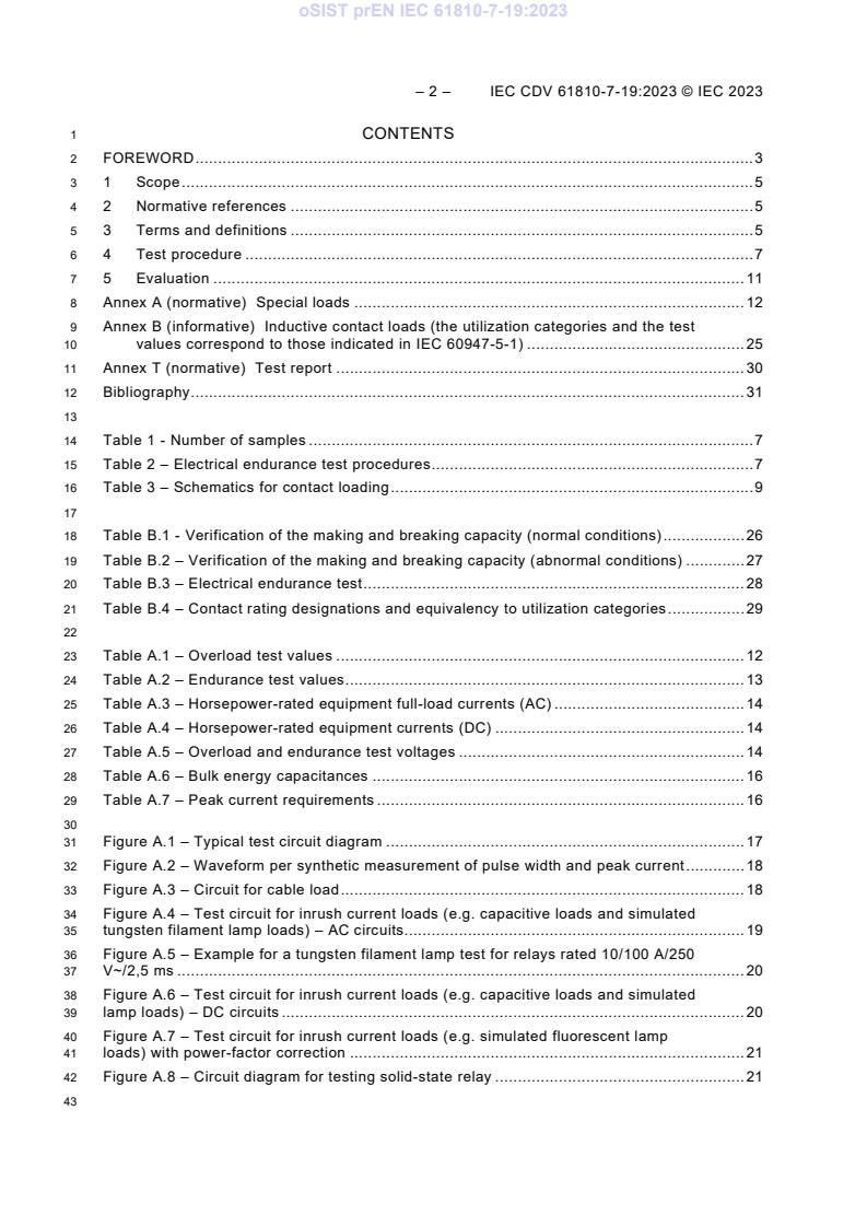
1 CONTENTS
2 FOREWORD . 3
3 1 Scope . 5
4 2 Normative references . 5
5 3 Terms and definitions . 5
6 4 Test procedure . 7
7 5 Evaluation . 11
8 Annex A (normative) Special loads . 12
9 Annex B (informative) Inductive contact loads (the utilization categories and the test
10 values correspond to those indicated in IEC 60947-5-1) . 25
11 Annex T (normative) Test report . 30
12 Bibliography . 31
14 Table 1 - Number of samples . 7
15 Table 2 – Electrical endurance test procedures . 7
16 Table 3 – Schematics for contact loading . 9
18 Table B.1 - Verification of the making and breaking capacity (normal conditions) . 26
19 Table B.2 – Verification of the making and breaking capacity (abnormal conditions) . 27
20 Table B.3 – Electrical endurance test . 28
21 Table B.4 – Contact rating designations and equivalency to utilization categories . 29
23 Table A.1 – Overload test values . 12
24 Table A.2 – Endurance test values . 13
25 Table A.3 – Horsepower-rated equipment full-load currents (AC) . 14
26 Table A.4 – Horsepower-rated equipment currents (DC) . 14
27 Table A.5 – Overload and endurance test voltages . 14
28 Table A.6 – Bulk energy capacitances . 16
29 Table A.7 – Peak current requirements . 16
31 Figure A.1 – Typical test circuit diagram . 17
32 Figure A.2 – Waveform per synthetic measurement of pulse width and peak current . 18
33 Figure A.3 – Circuit for cable load . 18
34 Figure A.4 – Test circuit for inrush current loads (e.g. capacitive loads and simulated
35 tungsten filament lamp loads) – AC circuits. 19
36 Figure A.5 – Example for a tungsten filament lamp test for relays rated 10/100 A/250
37 V~/2,5 ms . 20
38 Figure A.6 – Test circuit for inrush current loads (e.g. capacitive loads and simulated
39 lamp loads) – DC circuits . 20
40 Figure A.7 – Test circuit for inrush current loads (e.g. simulated fluorescent lamp
41 loads) with power-factor correction . 21
42 Figure A.8 – Circuit diagram for testing solid-state relay . 21
oSIST prEN IEC 61810-7-19:2023
IEC CDV 61810-7-19:2023 © IEC 2023 – 3 –
45 INTERNATIONAL ELECTROTECHNICAL COMMISSION
46 ____________
48 Electrical Relays –
49 Tests and measurements
51 Part 7-19: Electrical endurance
53 FOREWORD
54 1) The International Electrotechnical Commission (IEC) is a worldwide organization for standardization
55 comprising all national electrotechnical committees (IEC National Committees). The object of IEC is to p
56 2) romote international co-operation on all questions concerning standardization in the electrical and electronic
57 fields. To this end and in addition to other activities, IEC publishes International Standards, Technical
58 Specifications, Technical Reports, Publicly Available Specifications (PAS) and Guides (hereafter referred
59 to as "IEC Publication(s)"). Their preparation is entrusted to technical committees; any IEC National
60 Committee interested in the subject dealt with may participate in this preparatory work. International,
61 governmental and non-governmental organizations liaising with the IEC also participate in this preparation.
62 IEC collaborates closely with the International Organization for Standardization (ISO) in accordance with
63 conditions determined by agreement between the two organizations.
64 2) The formal decisions or agreements of IEC on technical matters express, as nearly as possible, an international
65 consensus of opinion on the relevant subjects since each technical committee has representation from all
66 interested IEC National Committees.
67 3) IEC Publications have the form of recommendations for international use and are accepted by IEC National
68 Committees in that sense. While all reasonable efforts are made to ensure that the technical content of IEC
69 Publications is accurate, IEC cannot be held responsible for the way in which they are used or for any
70 misinterpretation by any end user.
71 4) In order to promote international uniformity, IEC National Committees undertake to apply IEC Publications
72 transparently to the maximum extent possible in their national and regional publications. Any divergence between
73 any IEC Publication and the corresponding national or regional publication shall be clearly indicated in the latter.
74 5) IEC itself does not provide any attestation of conformity. Independent certification bodies provide conformity
75 assessment services and, in some areas, access to IEC marks of conformity. IEC is not responsible for any
76 services carried out by independent certification bodies.
77 6) All users should ensure that they have the latest edition of this publication.
78 7) No liability shall attach to IEC or its directors, employees, servants or agents including individual experts and
79 members of its technical committees and IEC National Committees for any personal injury, property damage or
80 other damage of any nature whatsoever, whether direct or indirect, or for costs (including legal fees) and
81 expenses arising out of the publication, use of, or reliance upon, this IEC Publication or any other IEC Publications.
82 8) Attention is drawn to the Normative references cited in this publication. Use of the referenced publications is
83 indispensable for the correct application of this publication.
84 9) Attention is drawn to the possibility that some of the elements of this IEC Publication may be the subject of patent
85 rights. IEC shall not be held responsible for identifying any or all such patent rights.
86 The International Standards of the IEC 61810 have been prepared by IEC technical committee
87 94: All-or-nothing electrical relays.
88 The text of this International Standard is based on the following documents:
CD CC
94/851/CD 94/913/CC
90 Full information on the voting for the approval of this International Standard can be found in the
91 report on voting indicated in the above table.
92 This document has been drafted in accordance with the ISO/IEC Directives, Part 2.
oSIST prEN IEC 61810-7-19:2023
– 4 – IEC CDV 61810-7-19:2023 © IEC 2023
93 A list of all parts of IEC 61810 series, published under the general title Electromechanical
94 elementary relays, can be found on the IEC website.
95 This International Standard is to be used in conjunction with IEC 61810-1:2015.
96 The committee has decided that the contents of this document will remain unchanged until the
97 stability date indicated on the IEC website under "http://webstore.iec.ch" in the data related to
98 the specific document. At this date, the document will be
99 • reconfirmed,
100 • withdrawn,
101 • replaced by a revised edition, or
102 • amended.
oSIST prEN IEC 61810-7-19:2023
IEC CDV 61810-7-19:2023 © IEC 2023 – 5 –
105 Electrical Relays –
106 Tests and measurements
108 Part 7-19: Electrical endurance
111 1 Scope
112 This part of IEC 61810-7 is used for testing along with the appropriate severities and conditions
113 for measurements and tests designed to assess the ability of specimens to perform under
114 expected conditions of transportation, storage and all aspects of operational use.
115 The object of this part gives guidance to perform different kind of electrical endurance.
116 2 Normative references
117 The following documents are referred to in the text in such a way that some or all of their content
118 constitutes requirements of this document. For dated references, only the edition cited applies.
119 For undated references, the latest edition of the referenced document (including any
120 amendments) applies.
121 IEC 60669-1:2017, Switches for household and similar fixed-electrical installations - Part 1:
122 General requirements
123 IEC 60947-5-1:2016, Low-voltage switchgear and controlgear - Part 5-1: Control circuit devices
124 and switching elements - Electromechanical control circuit devices
125 IEC 61810-7-0:202X, Electrical relays – Tests and Measurements - Part 7-0: Testing – General
126 and Guidance
127 IEC 61810-7-4:202X, Electrical relays – Tests and Measurements - Part 7-4: Dielectric strength
128 test
129 IEC 61810-7-6:202X, Electrical relays – Tests and Measurements - Part 7-6: Contact-circuit
130 resistance (or voltage drop)
131 IEC 61810-7-7:202X, Electrical relays – Tests and Measurements - Part 7-7: Functional Tests
132 IEC 61810-7-45:202X, Electrical relays – Tests and Measurements - Part 7-45: Maximum
133 frequency of operation
134 IEC 61810-10:2019, Electrical relays – Part 10: Additional functional aspects and safety
135 requirements for high-capacity relays
136 IEC 62246-1:2015, Reed Switches – Part 1: Generic Specification
137 3 Terms and definitions
138 For the purpose of this document, the terms and definitions given in clause 3 of IEC 61810-7-0
139 and the following apply
oSIST prEN IEC 61810-7-19:2023
– 6 – IEC CDV 61810-7-19:2023 © IEC 2023
140 3.1 Terms and definitions related to general terms
142 making and breaking capacities
143 greatest value of electric current which an output circuit is capable of making and breaking
144 under specified conditions such as contact voltage, number of makes and breaks, power factor,
145 time constant
146 Note For alternating current, the RMS value is specified.
147 [SOURCE: IEC 60050-444:2002, 444-04-30 and 444-04-31, merged – modification of the term
148 and definition]
150 overload
151 operating conditions in an electrically undamaged circuit, which cause an overcurrent
152 [SOURCE: IEC 60050-441:1984/AMD1:2000, 441-11-08]
154 utilization category
155 a combination of specified requirements related to the condition in which the switching device
156 or the fuse fulfils its purpose, selected to represent a characteristic group of practical
157 applications
158 Note The specified requirements may concern e.g. the values of making capacities (if applicable), breaking
159 capacities and other characteristics, the associated circuits and the relevant conditions of use and behaviour.
160 [SOURCE: IEC 60050-441:1984/AMD1:2000, 441-17-19]
oSIST prEN IEC 61810-7-19:2023
IEC CDV 61810-7-19:2023 © IEC 2023 – 7 –
162 4 Test procedure
163 4.1 Purpose
164 To check the performance of the relay under operating conditions and for the number of cycles
165 specified by the manufacturer.
166 NOTE With respect to the establishment and assessment of reliability data for relays reference is made to IEC 61810-
167 2.
168 4.2 Procedure
169 General
170 The test is performed according to Table 2 on each contact load and each contact material as
171 specified by the manufacturer.
172 The number of test samples shall be in compliance with the specified test procedure from
173 Table 1.
174 Table 1 - Number of samples
Kind of
Test procedure Number of samples Mounting conditions
testing
A 3 Group mounting
Type test
B 1 Single mounting
Sampling test n.a. 3 n.a.
176 Table 2 – Electrical endurance test procedures
a
Test procedure
A B B B
Procedure
(Group (Single (Single mounting) and (Single mounting) and
d e
mounting) mounting)
Annex B Annex A
Abnormal Conditions
c
Overload test Overload test Overload test
Parameter given in Annex B
(optional, see (optional, see Parameter given in
Normal Conditions
4.4) 4.4)
Annex A
Parameter given in Annex B
Test Electrical endurance
Electrical endurance
Electrical endurance Parameter given in
sequence
Parameter given in Annex B
Annex A
Dielectric strength test
b
Heating test
n.a. n.a.
(optional)
a
See also Table 1.
b
For application standards e.g. IEC 60730-1 or IEC 60669-1 the heating test after the electrical endurance is
requested.
c
For electronic ballast: overload test is not requested.
d Following exactly the requirements in accordance with Annex B.
e Following exactly the requirements in accordance with Annex A.
177 Three severity levels are specified.
178 – Severity A: The first detected malfunction is defined as a failure.
oSIST prEN IEC 61810-7-19:2023
– 8 – IEC CDV 61810-7-19:2023 © IEC 2023
179 – Severity B: The sixth detected malfunction or two consecutive malfunctions are defined as
180 a failure.
181 – Severity C: As specified by the manufacturer.
182 The test circuit described in Annex A of IEC 61810-7-0 shall be used, unless otherwise specified
183 by the manufacturer and explicitly indicated in the test report.
184 For high-capacity relays according IEC 61810-10 and reed switches according IEC 62246-1
185 applies only the following:
186 • Severity level A is mandatory.
187 • If the relay has a defined polarity of a contact, the manufacturer shall specify an appropriate
188 schematic for contact loading for the test, which may deviate from the schematics of Table 3.
189 The heating test after the electrical endurance is mandatory if prescribed by the relevant product
190 application for example Clause 8 and Annex E in IEC 61810-1, or by application standards (e.g.
191 IEC 60730-1 or IEC 60669-1).
192 Electrical endurance
193 Unless otherwise explicitly stated by the manufacturer, this test is carried out at the upper limit
194 of the ambient temperature range, and the relay coil(s) shall be energized with rated voltage or
195 an appropriate value within the rated coil voltage range or operative range.
196 The contacts shall be monitored to detect break and/or make malfunctions as well as unintended
197 bridging.
198 The preferred arrangement of the relays is group mounted under the mounting conditions of
199 Annex A of IEC 61810-7-10 for the heating test unless otherwise prescribed by the manufacturer.
200 For PCB relays it is permitted to use a PCB for connecting the relays with the wires and ensure
201 the minimum mounting distances. However, the dimensions of the connecting wires shall be
202 according to clause 4.9 of IEC 61810-7-0.
203 The contacts are connected to the load(s) in accordance with Table 3 as specified and indicated
204 by the manufacturer. If not otherwise specified by the manufacturer, the load shall be applied
205 to both the make and break side of a change-over contact.
206 If not otherwise specified, the frequency of operations shall be 360 operations per hour with
207 duty type S6 50% in accordance to IEC 61810-7-0 and for 6000 operations. However, the
208 frequency of operations shall be less than the maximum frequency of operation according to
209 IEC 61810-7-45.
210 Relays provided with an additional actuating member for manual operation (for example push-
211 button) shall be tested respectively to verify that the relay is capable to switch on and off
212 properly its maximum rated switching current at related voltage for the number of manual
213 operations within a time diagram stated by the manufacturer at ambient temperature in
214 accordance with Table 2 of IEC 61810-7-0 at least 100 times - if not otherwise specified by the
215 manufacturer.
oSIST prEN IEC 61810-7-19:2023
IEC CDV 61810-7-19:2023 © IEC 2023 – 9 –
217 Table 3 – Schematics for contact loading
Single-pole a b
contact
c d e
Double-pole
contact
f g h
i j
Multi-pole contact k l m
n
Change-over o p q
contact
r s t
u v w
If none of the schematics applies, the manufacturer shall indicate an appropriate one.
oSIST prEN IEC 61810-7-19:2023
– 10 – IEC CDV 61810-7-19:2023 © IEC 2023
219 4.3 Conditions to be specified
220 The conditions to be specified are the following:
221 a) type of relay and contact material;
222 b) total number of cycles or test duration for each contact and number of contacts to be tested
223 simultaneously;
224 c) severity level;
225 d) ambient conditions (particularly ambient temperature);
226 e) method of mounting;
227 f) energization value and, if required, frequency;
228 g) switching current, if other than rated current;
229 h) power factor (cos ϕ), time constant (L/R) and test circuit details as appropriate;
230 i) frequency of operation (in number of cycles per hour) and duty factor;
231 j) total number of cycles, if other than 6000 cycles;
232 k) protective and transient suppression devices, if required;
233 l) details of test circuit or checking equipment, adapters, etc., if required;
234 m) fuse rating, if required;
235 n) final measurements:
236 • dielectric test as specified in in IEC 61810-7-4 - for function isolation with 75 % of the
237 specified initial value for new condition;
238 • any other measurements as specified by the manufacturer.
240 Overload
241 To assess the performance of a relay when subjected to overload (fault) conditions.
242 During the test, the relay mounting face and any exposed metallic parts shall be connected to
243 the power supply negative and/or neutral point or earthed via a fuse rated at 5 % of the
244 maximum switching current, or 100 mA, whichever is the greater, unless otherwise specified.
245 NOTE 1 The relay mounting face (surface, cover, aso) is usually produced out of plastics. In such cases the surface
246 could be coated for instance with a conductive foil or prepared cover to ensure a proper connection.
247 NOTE 2 The layer should as thin as possible to ensure less influence back to the test – like cooling the surface.
248 An overload test shall be performed if the manufacturer specifies value(s) for the limiting making
249 and/or breaking capacity higher than the rated switching current (see Table 2).
250 The number of cycles shall be 50 ± 2 for DC contact loads, and 50 ± 2 for AC contact loads,
251 unless otherwise specified.
252 The overload test on a CO contact could be done sequentially – NO and NC contact side
253 separately.
254 There shall be no malfunction.
255 Following the overload test, the endurance test shall be performed on the same samples, under
256 the same test conditions and at the rated switching current. For CO contact the endurance test
257 shall be performed at the same time.
oSIST prEN IEC 61810-7-19:2023
IEC CDV 61810-7-19:2023 © IEC 2023 – 11 –
258 For inductive loads, see Annex B.
259 Dedicated device application tests and their test sequences as well test circuits for special
260 loads (e.g. lamp loads, cable loads) are compiled in Annex A.
261 The relay coil shall be energized as specified and subjected to the appropriate number of cycles
262 specified by the manufacturer at the rated frequency of operation and duty factor.
263 For DC loads the contacts should switch minimum twice their maximum rated current for a
264 resistive load at their maximum rated voltage, unless otherwise specified.
265 For AC loads the contacts should switch minimum twice their maximum rated current for an
266 inductive load at their rated voltage, unless otherwise specified.
267 Overload for high-capacity relays:
268 For the overload test, a number of cycles specified by the manufacturer is allowed.
269 Conditions to be specified
270 The conditions to be specified are the following:
271 a) method of mounting;
272 b) energization value, frequency of operation and duty factor;
273 c) switching current (fault condition), if other than twice the maximum rated current;
274 d) power factor (cos ϕ), time constant (L/R) and test circuit details as appropriate;
275 e) total number of cycles, if other than 50 cycles;
276 f) any specific operating conditions to enable the relay to meet its performance as declared
277 by the manufacturer and the number of contacts simultaneously loaded.
278 5 Evaluation
279 When the applicable failure criteria is not met, the relay has not passed the endurance test.
280 After performing the electrical endurance procedure – the dielectric strength test shall be
281 performed.
282 The test shall pass the requirements as defined by standards for the insulation coordination
283 and others stated by the manufacturer or given is standards.
284 Contact-circuit resistance in accordance to IEC 61810-7-6 and functional tests in accordance
285 to IEC 61810-7-7 shall be measured, if applicable.
286 Subsequently for all DUTs a visual inspection shall verify the electrical integrity of the DUTs.
287 For this purpose, it may be necessary to open the test DUTs, if applicable.
oSIST prEN IEC 61810-7-19:2023
– 12 – IEC CDV 61810-7-19:2023 © IEC 2023
289 Annex A
290 (normative)
292 Special loads
293 A.1 Dedicated device application tests and test sequences
294 For relays intended or dedicated device applications, the overload and endurance tests shall
295 be conducted in accordance with the test parameters defined in Tables A.1, A.2 and A.5.
296 Table A.1 – Overload test values
Intended device application Current Power factor
A
a
Across-the-line AC motor starting, single phase 6 times device full-load current 0,40 – 0,50
b c
Across-the-line DC motor starting 10 times device full-load current DC
c
DC General use 1,5 times device rated value DC
AC General use 1,5 times device rated value 0,75 – 0,80
a
DC Resistance 1,5 times device rated value DC
AC Resistance 1,5 times device rated value 1,0
AC Resistance air heating 1,5 times device rated value 1,0
c
DC Resistance air heating 1,5 times device rated value DC
AC Incandescent lamps (Tungsten) 1,5 times device rated value 0,75 – 0,80
DC Incandescent lamps (Tungsten) 1,5 times device rated value DC
AC Electrical discharge lamps (Ballast) 3,0 times device rated value 0,40 – 0,50
a
See Table A.3 for AC full load currents.
b
See Table A.4 for DC full load currents.
c
Load is a noninductive resistive load.
298 Following the overload test, the endurance test shall be performed on the same samples (for
299 change over contacts it is permitted to test both contact sides separately), under the same test
300 conditions and at the rated switching current as stated by the manufacturer or in accordance
301 with Table A.2.
302 The overload test shall consist of 50 cycles switching load conditions representing maximum
303 interrupting values of voltage, current, and power. During the overload test, there shall be no
304 electrical or mechanical breakdown of the equipment, no undue burning or pitting of the contacts
305 and no welding of the contacts. The fuse specified below shall not open.
306 The sample shall be connected to the rated load using the same size conductors from the
307 heating test, alternate single mounting path. The enclosure or wire mesh shall be connected
308 through a 30 A, non-time delay fuse connected to the portion of the test circuit considered least
309 likely to strike ground.
310 The cycle time shall be 1 s on and 9 s off. If it can be determined that for a duration less than
311 one second, the device conducts the test current without interrupting the circuit or being
312 adversely affected by heat and the device contacts are properly sealed before the break is
313 initiated as confirmed by oscilloscopic or oscillography measurements, the on time may be
314 reduced to that duration. The closed test circuit voltage is to be 100 % to 110 % of the overload
315 test voltage specified in Table A.5.
oSIST prEN IEC 61810-7-19:2023
IEC CDV 61810-7-19:2023 © IEC 2023 – 13 –
316 Table A.2 – Endurance test values
Intended device application Test current Power Number Test cycle time
A factor of cycles
On Off
a c
Across-the-line AC motor starting Twice full-load current 0,40 – 0,50 1 000 1/2 1/2
b h c
Across-the-line DC motor starting Twice full-load current DC 1 000 1/2 1/2
h
DC General use Rated current DC 6 000 1 e 9 e
d
AC General use Rated current 0,75 – 0,80 6 000 1 e 9 e
h
DC Resistance Rated current DC 6 000 1 e 9 e
AC Resistance Rated current 1,0 6 000 1 e 9 e
h
DC Resistance air heating i Rated current DC 100 000 1 e 9 e
AC Resistance air heating i Rated current 1,0 100 000 1 e 9 e
g f f
AC Incandescent lamps (Tungsten) Rated current 1,0 6 000 1 59
g f f
DC Incandescent lamps (Tungsten) Rated current DC 6 000 1 59
AC Electrical discharge lamps Twice rated current 0,40 – 0,50 6 000 1 9
(Standard ballast)
i i
AC Electrical discharge lamps 6 000 1 9
(Electronic ballast)
a
See Table A.3 for AC full load currents.
b
See Table A.4 for DC full load currents.
c
These devices are to be subjected to at least 6 000 mechanical cycles at any convenient rate.
d
If the device is marked "resistance only", the test may be conducted using a noninductive resistance
load. This "resistance only" rating is different than a resistance heating rating or a resistance air heating rating.
e
The cycle times are to be shown or as described in the overload test.
f
A control may be operated faster than 1 cycle per minute if synthetic loads are used or if a sufficient
number of banks of lamps controlled by a commutator are employed so that each bank will cool for at least 59 s
between successive applications.
g
For a magnetic relay intended to turn a television receiver on and off, the number of test cycles is to be
25 000, and the relay shall be marked "TV-X," where "TV" signifies the television and "X" is the ste
...