

SIST EN IEC 62368-1:2024/oprA1:2026
(Amendment)Amendment 1 - Audio/video, information and communication technology equipment - Part 1: Safety requirements
- Status
- Not Published
- Public Enquiry End Date
- 30-Dec-2026
- Technical Committee
- MOV - Measuring equipment for electromagnetic quantities
- Current Stage
- 4020 - Public enquire (PE) (Adopted Project)
- Start Date
- 10-Nov-2026
- Due Date
- 30-Mar-2027

SIST EN IEC 62368-1:2024/oprA1:2026 is a CENELEC amendment to the safety requirements for audio/video, information and communication technology equipment. It updates the hazard-based rules used by manufacturers, test laboratories, certification bodies, and other conformity-assessment teams to design and check equipment for electrical, fire, mechanical, and thermal safety. The amendment revises definitions, limits, test methods, and component requirements in Part 1, so readers can see exactly where the base standard is being changed.
What does SIST EN IEC 62368-1:2024/oprA1:2026 specify?
SIST EN IEC 62368-1:2024/oprA1:2026 amends Part 1 of the safety standard for AV/ICT equipment. The document keeps the hazard-based structure of clauses 0 to 9 and updates annexes that support UV exposure testing, markings, components, telephone ringing signals, batteries, electrochemical potentials, and an alternative clearance method.
| Annex | What it covers |
|---|---|
| Annex C | UV radiation and xenon-arc light-exposure testing |
| Annex F | Equipment markings, instructions, and instructional safeguards |
| Annex G | Components, including varistors, FIW, and ICX |
| Annex H | Criteria for telephone ringing signals |
| Annex M | Equipment containing batteries and their protection circuits |
| Annex N | Electrochemical potentials for dissimilar metals |
| Annex W | Comparison of terms introduced in the document |
| Annex X | Alternative clearance method for circuits connected to AC mains not exceeding 420 V peak (300 V RMS) |
The main clauses remain focused on principles and safeguards, scope, normative references, terms, general requirements, electrically-caused injury, electrically-caused fire, mechanically-caused injury, and thermal burn injury. In practice, that means the amendment touches the whole safety model rather than a single product feature.
What are the key requirements of SIST EN IEC 62368-1:2024/oprA1:2026?
SIST EN IEC 62368-1:2024/oprA1:2026 mainly changes how safeguards are selected, how energy sources are classified, and how compliance is checked. The most important updates are below.
Safeguards, scope, and terminology
Clause 0.5 revises the text for instructional safeguard and skill safeguard. If an energy source that can cause pain or injury is needed for correct operation, an instructional safeguard may be used instead of another safeguard, and it may require a personal safeguard. For servicing, a skilled person may remove or defeat a safeguard and then use skill as the safeguard. In practice, this affects labels, service instructions, and the way manufacturers justify access during maintenance.
Clause 1 adds equipment intended for tropical regions to the scope text. Clause 3 updates the definition of subassembly and adjusts the notes for fully insulated winding wire (FIW). This matters because subassemblies are treated as components in the final equipment, and FIW has special treatment in transformer windings and component selection.
Electrical injury and energy-source limits
Clause 5 revises the ES1 and ES2 steady-state voltage and current limits, including the frequency-dependent limits and the combined AC/DC figure. It also updates the rules for accessibility to electrical energy sources, including how FIW transformer windings may serve as basic or reinforced safeguards. In practical terms, designers need to verify accessible touch voltage and current using the stated measurement methods and the correct frequency range.
Clause 5 also updates clearances and transient-voltage handling, including the note that European requirements for interconnection with an external circuit are given in EN IEC 63044-3:2018. The resistance requirement for transient-voltage compliance is corrected, and the protective bonding language is aligned to “protective earthing”. For users of the standard, this means the insulation and external-circuit checks must be matched to the revised wording.
Electrically-caused fire and power-source classification
Clause 6 updates how power sources are measured and classified. PS1 is limited to 15 W after 3 s, PS2 does not exceed 100 W after 5 s, and PS3 is above PS2 or not classified. The amendment also introduces a method for classification by overcurrent protective device, using a fuse or a non-adjustable, non-autoreset electromechanical device that meets the stated limits. This matters because fire safeguards depend on the correct power-source class, not just the nominal rating of the circuit.
Clause 6 also tightens the requirements for PS2 and PS3 circuits under single fault conditions, and it updates the text for fire enclosures and fire barriers. The result is a more explicit link between component choice, fault testing, and enclosure design.
Mechanical injury and thermal burn injury
Clause 8 updates the classification of mechanical energy sources, including moving parts, fan blades, and mounting hazards. The emergency stop system for MS3 moving parts must override other controls, remove drive power, and use automatic braking if needed so hazardous live parts cannot be reached. For slide-rail mounted equipment, the warning wording for tipping risk is updated. In practice, these changes affect enclosure design, fan selection, and instructions for rack mounting.
Clause 9 updates the touch-temperature table and the related test method and compliance criteria. The table distinguishes between surface materials and contact duration, and it allows specific instructional safeguards for some hot parts. This tells manufacturers what surface temperatures are acceptable for devices held in the hand, worn on the body, or touched only briefly.
Components and special product cases
The annexes update several component rules. Annex C changes the xenon-arc light-exposure test; Annex F updates example markings and instructional safeguards; Annex G revises FIW tables, varistor testing, capacitor selection, and ICX testing; Annex H updates the criteria for telephone ringing signals; Annex M updates battery-related safeguards and references for secondary batteries; Annex N updates electrochemical-potential data used to reduce galvanic corrosion risk; and Annex X gives an alternative clearance method for certain AC mains circuits.
What terms does SIST EN IEC 62368-1:2024/oprA1:2026 define?
- Subassembly - A unit built separately to be incorporated into larger equipment and not able to work independently from the final product.
- Fully insulated winding wire (FIW) - Winding wire used in transformer windings, with special safety treatment in the component rules.
- Instructional safeguard - A safeguard based on instructions that can be used when exposure to an energy source is needed for correct operation.
- Skill safeguard - Protection that relies on the action of a skilled person during servicing to avoid injury or fire.
- ES1 - An electrical energy source level with voltage or current limited to the ES1 limits used in the document.
- PS1 - A power source class where the measured power source does not exceed 15 W after 3 s.
- PS2 - A power source class that exceeds PS1 but does not exceed 100 W after 5 s.
- SRME - Slide-rail mounted equipment, which has special mounting and stability requirements.
Who uses SIST EN IEC 62368-1:2024/oprA1:2026?
SIST EN IEC 62368-1:2024/oprA1:2026 is used by product designers, safety engineers, test laboratories, certification bodies, quality managers, and compliance teams working on AV, ICT, and communication equipment. It is also relevant to component suppliers because the document sets special rules for items such as FIW, varistors, capacitors, batteries, and protective devices.
In practice, these users apply the standard when they are:
- choosing safeguards for accessible energy sources
- checking clearances, insulation, and touch current
- classifying PS1, PS2, and PS3 circuits
- designing fire enclosures and barriers
- defining labels and instructions
- verifying battery protection circuits and mounting stability
- running type tests and fault-condition tests on the final equipment
What changed in SIST EN IEC 62368-1:2024/oprA1:2026 from the previous edition?
SIST EN IEC 62368-1:2024/oprA1:2026 is Amendment 1 to Part 1, and it updates several areas of the base text. The amendment adds tropical regions to the scope wording, adds ISO 4892-2:2013/AMD1:2021 to the normative references, revises the definitions of subassembly and FIW, and updates the text for instructional safeguard and skill safeguard.
It also revises ES1 and ES2 limits, power-source classification, clearances, fire safeguards, moving-part safeguards, touch-temperature limits, UV testing, FIW tables, varistor testing, capacitor rules, battery safeguards, and the alternative clearance table in Annex X.
Which standards are used with SIST EN IEC 62368-1:2024/oprA1:2026?
SIST EN IEC 62368-1:2024/oprA1:2026 uses several companion standards and test documents:
- ISO 4892-2:2013/AMD1:2021 - laboratory light-source exposure for the xenon-arc UV test in Annex C.
- IEC 60479-1 and IEC 60479-2 - the shock-current basis behind the ES1 and ES2 limits.
- IEC 60990:2016 - the measuring networks used for touch-current measurements.
- IEC 60317-0-7:2017, IEC 60317-56, and IEC 60851-5 - qualification and testing references for FIW.
- IEC 61051-2:2021 and IEC 61643-331:2020 - pulse tests for varistors.
- IEC 60384-14 - capacitor subclass ratings used in Annex G.
- IEC 62133-2 and IEC 62619 - battery standards referenced for some stationary and secondary battery applications.
- IEC TR 62368-2:2025 - explanatory information related to IEC 62368-1.
- EN IEC 63044-3:2018 - European electrical safety guidance for interconnection with external circuits.
What does the SIST EN IEC 62368-1:2024/oprA1:2026 document contain?
SIST EN IEC 62368-1:2024/oprA1:2026 contains updated tables, figures, formulas, and test methods rather than only narrative text. The document includes revised tables for electrical energy-source limits, power-source classification, mechanical energy-source classes, touch-temperature limits, FIW dimensions and test voltages, capacitor ratings, electrochemical potentials, and alternative clearances.
It also contains test procedures and compliance checks for xenon-arc UV exposure, worst-case power measurements, varistor pulse testing, battery protection, telephone ringing signals, and fire-related component behavior. These parts are used for design verification, laboratory testing, and conformity assessment of the finished equipment.
Several figures support the measurement and classification methods, including the figures for power-source classification, bottom and side openings, and combined AC/DC limits. For engineers, those figures are important because they show the exact test setup or classification logic rather than leaving it to interpretation.
Relations
- Effective Date
- 29-Jul-2025
Get Certified
Connect with accredited certification bodies for this standard

BSI Group
BSI (British Standards Institution) is the business standards company that helps organizations make excellence a habit.

NYCE
Mexican standards and certification body.

ANCE
Mexican certification and testing association.
Sponsored listings
Frequently Asked Questions
SIST EN IEC 62368-1:2024/oprA1:2026 is a draft published by the Slovenian Institute for Standardization (SIST). Its full title is "Amendment 1 - Audio/video, information and communication technology equipment - Part 1: Safety requirements". This standard covers: Amendment 1 - Audio/video, information and communication technology equipment - Part 1: Safety requirements
Amendment 1 - Audio/video, information and communication technology equipment - Part 1: Safety requirements
SIST EN IEC 62368-1:2024/oprA1:2026 is classified under the following ICS (International Classification for Standards) categories: 33.160.01 - Audio, video and audiovisual systems in general; 35.020 - Information technology (IT) in general. The ICS classification helps identify the subject area and facilitates finding related standards.
SIST EN IEC 62368-1:2024/oprA1:2026 has the following relationships with other standards: It is inter standard links to SIST EN IEC 62368-1:2024. Understanding these relationships helps ensure you are using the most current and applicable version of the standard.
SIST EN IEC 62368-1:2024/oprA1:2026 is associated with the following European legislation: Standardization Mandates: M/452, M/511, M/536. When a standard is cited in the Official Journal of the European Union, products manufactured in conformity with it benefit from a presumption of conformity with the essential requirements of the corresponding EU directive or regulation.
SIST EN IEC 62368-1:2024/oprA1:2026 is available in PDF format for immediate download after purchase. The document can be added to your cart and obtained through the secure checkout process. Digital delivery ensures instant access to the complete standard document.
Standards Content (Sample)
SLOVENSKI STANDARD
01-december-2026
Oprema za avdio/video, informacijsko in komunikacijsko tehnologijo - 1. del:
Varnostne zahteve - Dopolnilo A1
Amendment 1 - Audio/video, information and communication technology equipment -
Part 1: Safety requirements
Einrichtungen für Audio/Video-, Informations- und Kommunikationstechnik - Teil 1:
Sicherheitsanforderungen
Equipements des technologies de l'audio/vidéo, de l'information et de la communication -
Partie 1: Exigences de sécurité
Ta slovenski standard je istoveten z: EN IEC 62368-1:2024/prA1:2026
ICS:
33.160.01 Avdio, video in avdiovizualni Audio, video and audiovisual
sistemi na splošno systems in general
35.020 Informacijska tehnika in Information technology (IT) in
tehnologija na splošno general
2003-01.Slovenski inštitut za standardizacijo. Razmnoževanje celote ali delov tega standarda ni dovoljeno.
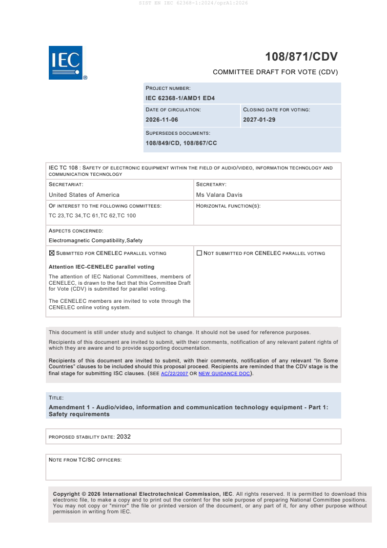
108/871/CDV
COMMITTEE DRAFT FOR VOTE (CDV)
PROJECT NUMBER:
IEC 62368-1/AMD1 ED4
DATE OF CIRCULATION: CLOSING DATE FOR VOTING:
2026-11-06 2027-01-29
SUPERSEDES DOCUMENTS:
108/849/CD, 108/867/CC
IEC TC 108 : SAFETY OF ELECTRONIC EQUIPMENT WITHIN THE FIELD OF AUDIO/VIDEO, INFORMATION TECHNOLOGY AND
COMMUNICATION TECHNOLOGY
SECRETARIAT: SECRETARY:
United States of America Ms Valara Davis
OF INTEREST TO THE FOLLOWING COMMITTEES: HORIZONTAL FUNCTION(S):
TC 23,TC 34,TC 61,TC 62,TC 100
ASPECTS CONCERNED:
Electromagnetic Compatibility,Safety
SUBMITTED FOR CENELEC PARALLEL VOTING NOT SUBMITTED FOR CENELEC PARALLEL VOTING
Attention IEC-CENELEC parallel voting
The attention of IEC National Committees, members of
CENELEC, is drawn to the fact that this Committee Draft
for Vote (CDV) is submitted for parallel voting.
The CENELEC members are invited to vote through the
CENELEC online voting system.
This document is still under study and subject to change. It should not be used for reference purposes.
Recipients of this document are invited to submit, with their comments, notification of any relevant patent rights of
which they are aware and to provide supporting documentation.
Recipients of this document are invited to submit, with their comments, notification of any relevant “In Some
Countries” clauses to be included should this proposal proceed. Recipients are reminded that the CDV stage is the
final stage for submitting ISC clauses. (SEE AC/22/2007 OR NEW GUIDANCE DOC).
TITLE:
Amendment 1 - Audio/video, information and communication technology equipment - Part 1:
Safety requirements
PROPOSED STABILITY DATE: 2032
NOTE FROM TC/SC OFFICERS:
electronic file, to make a copy and to print out the content for the sole purpose of preparing National Committee positions.
You may not copy or "mirror" the file or printed version of the document, or any part of it, for any other purpose without
permission in writing from IEC.
IEC CDV 62368-1/AMD1 © IEC 2026
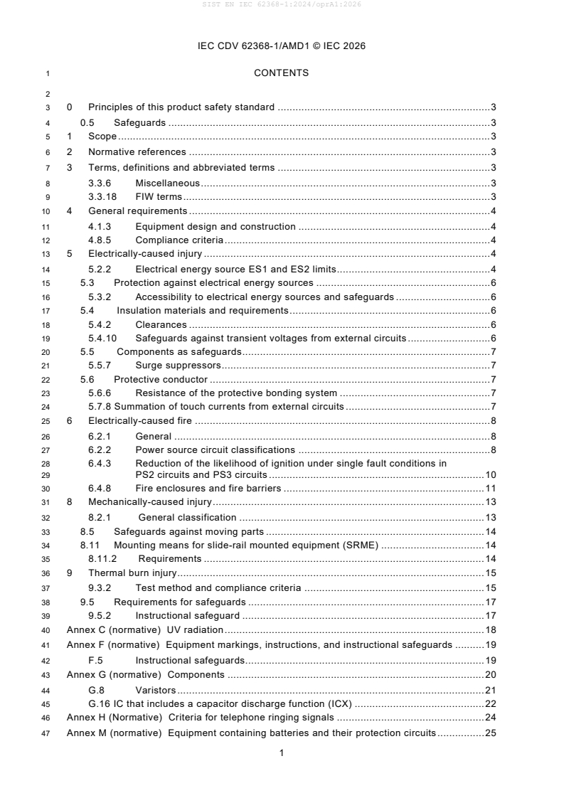
1 CONTENTS
3 0 Principles of this product safety standard . 3
4 0.5 Safeguards . 3
5 1 Scope . 3
6 2 Normative references . 3
7 3 Terms, definitions and abbreviated terms . 3
8 3.3.6 Miscellaneous . 3
9 3.3.18 FIW terms . 3
10 4 General requirements . 4
11 4.1.3 Equipment design and construction . 4
12 4.8.5 Compliance criteria . 4
13 5 Electrically-caused injury . 4
14 5.2.2 Electrical energy source ES1 and ES2 limits . 4
15 5.3 Protection against electrical energy sources . 6
16 5.3.2 Accessibility to electrical energy sources and safeguards . 6
17 5.4 Insulation materials and requirements . 6
18 5.4.2 Clearances . 6
19 5.4.10 Safeguards against transient voltages from external circuits . 6
20 5.5 Components as safeguards . 7
21 5.5.7 Surge suppressors . 7
22 5.6 Protective conductor . 7
23 5.6.6 Resistance of the protective bonding system . 7
24 5.7.8 Summation of touch currents from external circuits . 7
25 6 Electrically-caused fire . 8
26 6.2.1 General . 8
27 6.2.2 Power source circuit classifications . 8
28 6.4.3 Reduction of the likelihood of ignition under single fault conditions in
29 PS2 circuits and PS3 circuits . 10
30 6.4.8 Fire enclosures and fire barriers . 11
31 8 Mechanically-caused injury . 13
32 8.2.1 General classification . 13
33 8.5 Safeguards against moving parts . 14
34 8.11 Mounting means for slide-rail mounted equipment (SRME) . 14
35 8.11.2 Requirements . 14
36 9 Thermal burn injury. 15
37 9.3.2 Test method and compliance criteria . 15
38 9.5 Requirements for safeguards . 17
39 9.5.2 Instructional safeguard . 17
40 Annex C (normative) UV radiation . 18
41 Annex F (normative) Equipment markings, instructions, and instructional safeguards . 19
42 F.5 Instructional safeguards. 19
43 Annex G (normative) Components . 20
44 G.8 Varistors . 21
45 G.16 IC that includes a capacitor discharge function (ICX) . 22
46 Annex H (Normative) Criteria for telephone ringing signals . 24
47 Annex M (normative) Equipment containing batteries and their protection circuits . 25
IEC CDV 62368-1/AMD1 © IEC 2026
48 M.1 General requirements . 25
49 M.2 Safety of batteries and their cells . 25
50 M.4 Additional safeguards for equipment containing a secondary lithium battery . 25
51 Annex N (normative) Electrochemical potentials (V) . 26
52 Annex W (informative) Comparison of terms introduced in this document. 29
53 Annex X (normative) Alternative method for determining clearances for insulation in
54 circuits connected to an AC mains not exceeding 420 V peak (300 V RMS) . 30
55 Bibliography . 30
IEC CDV 62368-1/AMD1 © IEC 2026
59 0 Principles of this product safety standard
60 0.5 Safeguards
61 Replace the fifth paragraph with following:
62 0.5.5.2 Instructional safeguard
63 If exposure to an energy source capable of causing pain or injury is essential to the correct
64 functioning of equipment, an instructional safeguard may be used to ensure protection of
65 persons instead of another safeguard. The instructional safeguard may require a personal
66 safeguard.
68 0.5.5.4 Skill safeguard (used by a skilled person)
69 Replace the second paragraph with following:
70 During equipment servicing, it is possible that a skilled person will need to remove or defeat
71 an equipment safeguard. In this case, a skilled person is expected to then apply skill as a
72 safeguard to avoid injury or fire.
73 1 Scope
74 In the third paragraph replace the fifth dash with the following:
75 – equipment intended to be used in tropical regions.
76 2 Normative references
77 Add the following normative reference:
78 ISO 4892-2:2013/AMD1:2021, Plastics – Methods of exposure to laboratory light sources – Part
79 2: Xenon-arc lamps
80 3 Terms, definitions and abbreviated terms
81 3.3.6 Miscellaneous
82 3.3.6.21 subassembly
83 Replace the text with the following:
84 unit assembled separately and designed to be incorporated with other units into a larger
85 manufactured equipment and that cannot work independently from the final equipment.
86 Note 1 to entry: A subassembly shall be regarded as a component in the final equipment.
87 3.3.18 FIW terms
88 3.3.18.1
89 fully insulated winding wire
90 FIW
91 Delete the last sentence of Note 1 to entry.
92 Add the following to the end of Note 2 to entry:
93 Some standards use FIW as winding wire that exhibits no electrical discontinuities when tested under specific
94 conditions.
IEC CDV 62368-1/AMD1 © IEC 2026
96 4 General requirements
97 4.1.3 Equipment design and construction
98 Replace the first dash in the third paragraph with the following:
99 – for ordinary person servicing, class 2 energy sources in accordance with 4.3.2.3, where
100 an instructional safeguard is provided in accordance with Clause F.5, except that element
101 3 is optional; or
102 Add this new dash after the last dash in the third paragraph:
103 – for safeguards that only act as a fire enclosure or fire barrier.
104 4.8.5 Compliance criteria
105 Replace the last dashed item with the following:
106 – it shall not be possible to remove the battery from the equipment with the test hook of Figure
107 20 using a force of not more than 20 N.
108 5 Electrically-caused injury
109 5.2.2 Electrical energy source ES1 and ES2 limits
110 5.2.2.2 Steady state voltage and current limits
111 Replace Table 4 with the following:
Secretary Note:
Only the formulas in Column ES1 and ES2 limits, Current, RMS, Row AC > 1 kHz up to 100 kHz has have been
updated
IEC CDV 62368-1/AMD1 © IEC 2026
113 Table 4 – Electrical energy source limits for steady state ES1 and ES2
ES3
ES1 limits ES2 limits
Energy
source
a, c, d b, c, e
Voltage Current Voltage Current
C
DC 60V 2 mA 120 V 25 mA
U = 30 V U = 50 V
RMS RMS
AC up to
1 kHz
U = 42,4 V U = 70,7 V
peak peak
AC
U = (30 + 0,4 𝑓𝑓) V I = 0,5 mA
RMS RMS
U = (50 + 0,9 𝑓𝑓) V I = 5 mA
RMS RMS
> 1 kHz
up to
U = (42,4 + 0,4√2 𝑓𝑓) V I = 0,707 mA U = (70,7 + 0,9√2 𝑓𝑓) V I = 7,07 mA
peak peak peak peak
> ES2
100 kHz
U = 70 V
AC above RMS U = 140 V
RMS
100 kHz Upeak = 198 V
U = 99 V
peak
U (V) U (V)
I (mA) I (mA)
DC AC RMS
DC AC RMS
+ ≤1
+ ≤1
60 U
RMS limit 0,5
Combined
AC and See Figure 23 See Figure 22
DC ᶠ
U (V) U (V)
I (mA) I (mA)
DC AC peak AC peak
DC
+ ≤1 + ≤1
60 U
2 0,707
peak limit
As an alternative to the requirements above, the values below can be used for purely sinusoidal waveforms
ES1 limits ES2 limits
Energy
a
Current , ᶜ Current ᵇ, ᶜ ES3
source
RMS RMS
AC up to
0,5 mA 5 mA
1 kHz
AC
> 1 kHz 𝑓𝑓 0,95 𝑓𝑓
e
IRMS = (0,5 𝑥𝑥 ) mA ᵈ 𝐼𝐼 = (5 + ) mA > ES2
RMS
up to 1 𝑘𝑘𝑘𝑘𝑘𝑘
1 𝑘𝑘𝑘𝑘𝑘𝑘
100 kHz
AC above
50 mA ᵈ 100 mA ᵉ
100 kHz
Peak values shall be used for non-sinusoidal voltage and current. RMS values can be used only for sinusoidal voltage and current.
See 5.7 for measurement of prospective touch voltage and touch current.
Electric shock current limits are taken from IEC 60479-1 and IEC 60479-2.
𝑓𝑓 is in kHz
a Current is measured using the measuring network specified in Figure 4 of IEC 60990:2016.
b Current is measured using the measuring network specified in Figure 5 of IEC 60990:2016.
c For sinusoidal waveforms and DC, the current may be measured using a 2000 Ω resistor.
d Above 22 kHz the accessible area is limited to 1 cm².
e Above 36 kHz the accessible area is limited to 1 cm².
f U is determined from the RMS voltage limit corresponding to the applicable frequency, and U is determined from the
RMS limit peak limit
peak voltage limit corresponding to the applicable frequency.
IEC CDV 62368-1/AMD1 © IEC 2026
116 Replace Figure 23 with the following:
Secretary Note:
The “(V)” replaces (mA) twice in the bottom and in the left of the figure.
The rest of Figure 23 is identical with the previous figure.
119 Figure 23 – Maximum values for combined AC voltage and DC voltage
120 5.3 Protection against electrical energy sources
121 5.3.2 Accessibility to electrical energy sources and safeguards
122 5.3.2.1 Requirements
123 Replace the last dashed item of the first paragraph with the following:
124 – an ES3 basic safeguard; and
125 – FIW transformer windings serving as an ES2 basic safeguard; and
126 – FIW transformer windings serving as an ES3 reinforced safeguard.
127 Replace the last dashed item of the third paragraph with the following:
128 – an ES3 basic safeguard; and
129 – FIW transformer windings serving as an ES3 reinforced safeguard.
130 5.4 Insulation materials and requirements
131 5.4.2 Clearances
132 5.4.2.3.2.4 Determining external circuit transient voltages
133 Replace Note 3 with the following:
134 NOTE 3 In Europe, the requirement for interconnection with an external circuit is in addition given in EN
135 IEC 63044-3:2018.
136 5.4.10 Safeguards against transient voltages from external circuits
137 5.4.10.3 Compliance criteria
138 In the last dash, replace the 2 MW with 2 MΩ.
IEC CDV 62368-1/AMD1 © IEC 2026
139 5.5 Components as safeguards
140 5.5.7 Surge suppressors
141 Replace NOTE 2 with the following:
142 NOTE 2 In class II equipment, surge suppressors are sometimes used between the mains and an external circuit
143 as defined in Table 13, ID 1a, 1b and 1c to protect internal circuits from a lightning surge. Information related to the
144 use of surge suppressors for such purposes is given in IEC TR 62368-2:2025, Annex A.
145 5.6 Protective conductor
146 5.6.6 Resistance of the protective bonding system
147 5.6.6.1 Requirements
148 In the third paragraph, replace the term “protective earth” with “protective earthing”.
149 5.7.8 Summation of touch currents from external circuits
150 Replace in the first dash of the sixth paragraph in a) 1) “connection to protective earth” with
151 “protective earthing connection”.
152 Replace in the second dash of the sixth paragraph in a) 1) “connection to protective earth” with
153 “protective earthing connection”.
154 Replace in the fourth paragraph in a) “protective earth” with “protective earthing”.
155 Replace the last paragraph with the following:
156 A capacitively coupled AC source of the same frequency and phase as the AC mains is applied
157 to each circuit of the equipment that can be connected to an external circuit so that 0,25 mA,
158 or the actual current from the other equipment if known to be lower, is available to flow into that
159 circuit. Common connection points are tested in accordance with 5.7.3, whether or not the points
160 are accessible.
IEC CDV 62368-1/AMD1 © IEC 2026
162 6 Electrically-caused fire
163 6.2.1 General
164 Replace the first paragraph with the following:
165 Electrical sources of heating may be declared (see 4.2.4) or classified into available power
166 levels PS1, PS2 and PS3 (see 6.2.2.4 and 6.2.2.5) that can cause resistive heating of both
167 components and connections. These power sources are based on available energy to a circuit.
Secretary Note:
There are no changes to Figure 34.
170 6.2.2 Power source circuit classifications
171 6.2.2.2 Power measurement for worst-case load fault
172 Replace the text with the following:
173 With reference to Figure 34:
174 – the measurement may be performed without the load circuit L connected, unless the
NL
175 maximum power or voltage is dependent on the connection of the load;
176 – at points X and Y, insert a wattmeter (or a voltmeter, V , and a current meter, I ); and
A A
177 – connect a variable resistor, L , as shown;
VR
178 • adjust the variable resistor, L , until the power source delivers the maximum power in
VR
179 a steady state and classify the power source according to 6.2.2.4 or
180 • obtain the maximum output voltage (U ) of the power source, measured with worst case
VA
181 load condition (for example, all load circuits disconnected) and classify the power source
182 according to 6.2.2.5.
183 If a power limiting device or circuit operates during the test, the measurement shall be repeated
184 at a point just below the current at which the power limiting device or circuit operated.
185 When evaluating accessories connected via cables to the equipment, the impedance of the
186 cable should be taken into account in the determination of PS1 or PS2 on the accessory side.
187 6.2.2.3 Power measurement for worst-case power source fault
188 Replace the text with the following:
Secretary Note:
There are no changes to Figure 35
191 With reference to Figure 35:
192 – At points X and Y, insert a wattmeter (or a voltmeter, V , and a current meter, I ).
A A
193 – Within the power source circuit, simulate any single fault condition that will result in
194 maximum power to the circuit being classified. All relevant components in the power source
195 circuits shall be short-circuited or disconnected one at a time at each measurement.
196 – Equipment containing audio amplifiers shall also be tested under abnormal operating
197 conditions as specified in Clause E.3.2.
198 – Measure
199 • the maximum power as specified and classify circuits supplied by the power source
200 according to 6.2.2.4; or
201 • the maximum voltage (UVA) after 3 s and classify circuits supplied by the power source
202 according to 6.2.2.5.
203 If a power limiting device or circuit operates during the test, the measurement shall be repeated
204 at a point just below the current at which the power limiting device or circuit operated.
IEC CDV 62368-1/AMD1 © IEC 2026
205 When the tests are repeated, a variable resistance may be used to simulate the component
206 under fault.
207 To avoid damage to the components of the normal load, a resistor (equal to the normal load)
208 may be substituted for the normal load.
209 NOTE Experimentation may be used to identify the single component fault that produces maximum power.
210 6.2.2.4 Power source classification without relying on an overcurrent protective
211 device
212 Replace all of 6.2.2.4 to 6.2.2.6 with the following:
Secretary Note:
Only the new heading for 6.2.2.4 and the text for 6.2.2.4.1 have been added. All other changes relate to the renumbering
required by the addition.
No other changes involved.
213 6.2.2.4.1 General
214 IC current limiters used for current limiting in power sources so that the available output power
215 becomes PS1 or PS2 are not shorted from input to output if they comply with G.9.
216 PTC thermistors used for current limiting shall comply with G.3.3.
217 Overcurrent protective devices operating during the test of 6.2.2.2 or 6.2.2.3 shall be short-
218 circuited and the measurement shall be repeated.
219 6.2.2.4.2 PS1
220 PS1 is a circuit where the power source, (see Figure 36) measured according to 6.2.2, does
221 not exceed 15 W measured after 3 s.
222 6.2.2.4.3 PS2
223 PS2 is a circuit where the power source, (see Figure 36) measured according to 6.2.2:
224 – exceeds PS1 limits; and
225 – does not exceed 100 W measured after 5 s.
226 Circuits that have previously been evaluated and comply with Annex Q are considered not to
227 be higher than PS2. All safeguards and requirements for PS2 apply.
228 NOTE Such circuits were typically tested according to IEC 60950-1.
229 6.2.2.4.4 PS3
230 PS3 is a circuit whose power source exceeds PS2 limits, or any circuit whose power source has
231 not been classified (see Figure 36).
IEC CDV 62368-1/AMD1 © IEC 2026
233 Figure 36 – Illustration of power source classification
234 Add new 6.2.2.5 and Table 33A as follows:
235 6.2.2.5 Power source classification by use of overcurrent protective device
236 Where an overcurrent protective device is used for limiting the power of a power source, it shall
237 be a fuse or a non-adjustable, non-autoreset, electromechanical device.
238 The overcurrent protective device shall comply with G.3.4.
239 The rated voltage of the overcurrent protective device shall be not less than the maximum
240 voltage UVA measured in 6.2.2.2 and 6.2.2.3.
241 The power source shall be limited in compliance with Table 33A and classified accordingly.
242 Table 33A – Limits for power sources limited by overcurrent protective devices
a
Current rating of the overcurrent protective device
Resulting power source classification
I
R
15 𝑊𝑊
𝐼𝐼 ≤ PS1
𝑅𝑅
𝑈𝑈
𝑉𝑉𝑉𝑉
15𝑊𝑊 100 𝑊𝑊
<𝐼𝐼 ≤ PS2
𝑅𝑅
𝑈𝑈 𝑈𝑈
𝑉𝑉𝑉𝑉 𝑉𝑉𝑉𝑉
100 𝑊𝑊
𝐼𝐼 > PS3
𝑅𝑅
𝑈𝑈
𝑉𝑉𝑉𝑉
a
The current rating of overcurrent protective devices is based on fuses and circuit breakers that break the circuit within 120 s
with a current equal to 210 % of the current rating specified in the table.
243 6.4.3 Reduction of the likelihood of ignition under single fault conditions in PS2
244 circuits and PS3 circuits
245 6.4.3.1 Requirements
246 Replace the third dashed item with the following:
247 – protective devices acting as a safeguard shall comply with G.3.1 to G.3.4 or the relevant IEC
248 component standards in accordance with 4.1.2;
249 Replace the fourth dashed item with the following:
IEC CDV 62368-1/AMD1 © IEC 2026
250 – motors and transformers shall comply with G.5.3, G.5.4 or the relevant IEC component
251 standard in accordance with 4.1.2;
252 Replace the sixth dashed item with the following:
253 – components associated with the mains shall comply with the relevant IEC component
254 standards in accordance with 4.1.2 and the requirements of other parts of this document.
255 6.4.8 Fire enclosures and fire barriers
256 6.4.8.3.4 Bottom openings and bottom opening properties
257 Replace Figure 44 with the following:
259 Figure 44 – Application of bottom opening requirements
IEC CDV 62368-1/AMD1 © IEC 2026
262 6.4.8.3.5 Side open
...