

oSIST prEN 410:2025
(Main)Glass in building - Determination of luminous and solar characteristics of glazing
- Abstract
This document specifies methods of determining the luminous and solar characteristics of glazing in buildings. These characteristics can serve as a basis for lighting, heating and cooling calculations of rooms and permit comparison between different types of glazing.
This document applies both to conventional glazing and to absorbing or reflecting solar-control glazing, used as vertical or horizontal glazed apertures. The appropriate formulae for single, double and triple glazing are given. A matrix method is provided as an alternative calculation method.
This document introduces a method to determine the luminous and solar properties of Building-Integrated Photovoltaic (BIPV) glazing.
This document is applicable to all transparent materials except those which show significant transmission in the wavelength region from 5 µm to 50 µm of ambient temperature radiation, such as certain plastic materials.
Materials with light-scattering properties are not covered by this document.
NOTE CEN/TC 129 is preparing standards on measurement and calculation of luminous and spectral properties of materials with light-scattering properties. Until this is available, the methodology in this document can continue to be applied to materials with light-scattering properties.
Angular light and solar properties of glass in building are excluded from this document. Research work in this area is summarized in Bibliographic references [1], [2] and [3].
Guidance on the measurement of luminous and spectral properties of glass can be found in the Bibliography [4].
The background to Annex E on BIPV glazing can be found in the Bibliography [11].
Vacuum Insulating Glass (VIG) is excluded from the scope of this document. For determination of the g value of VIG, please refer to ISO 19916-1 [13].
- Status
- Not Published
- Public Enquiry End Date
- 27-Feb-2025
- Technical Committee
- STV - Steklo, svetloba in razsvetljava v gradbeništvu
- Current Stage
- 4020 - Public enquire (PE) (Adopted Project)
- Start Date
- 30-Dec-2024
- Due Date
- 19-May-2025
- Completion Date
- 24-Mar-2025

oSIST prEN 410:2025 is the Slovenian draft version of the European Standard prEN 410 from CEN/TC 129, published through SIST. It specifies methods for determining the luminous and solar characteristics of glazing in buildings, including the values used for lighting, heating and cooling calculations and for comparing glazing products. It also extends the calculation framework to BIPV glazing.
What does oSIST prEN 410:2025 specify?
oSIST prEN 410:2025 specifies how to calculate the optical and solar performance of glazing in buildings. The standard is written for conventional glazing, solar-control glazing, and BIPV glazing, and it gives the calculation structure for single, double, triple, and more complex multi-pane systems.
The scope covers glazing used as vertical or horizontal glazed apertures. It applies to transparent materials except those with significant transmission in the 5 µm to 50 µm wavelength region of ambient-temperature radiation, and it excludes angular light and solar properties and Vacuum Insulating Glass (VIG).
Clauses 1 to 7 cover the scope, normative references, terms and definitions, symbols, determination of characteristics, expression of results, and the test report. Annexes A to F give the calculation procedures and worked examples that support the main formulas.
| Annex | What it covers |
|---|---|
| Annex A | Calculating spectral transmittance and reflectance for glass plates with different thickness and/or colour |
| Annex B | Calculating spectral characteristics of laminated glass |
| Annex C | Calculating spectral characteristics of screen printed glass |
| Annex D | Matrix method for non-scattering incoherent optical systems and total solar energy transmittance for multi-pane glazing units |
| Annex E | Modifications for calculation and declaration of BIPV glazing properties |
| Annex F | Example calculation of the colour rendering index |
What are the key requirements of oSIST prEN 410:2025?
oSIST prEN 410:2025 turns spectral data into standard glazing performance values. In practice, the standard tells you what to measure, which illuminant or radiation distribution to use, how to combine pane data, and how to report the final numbers so different glazing products can be compared on the same basis.
Calculation basis and measurement direction
Clause 5.1 sets the calculation basis as quasi-parallel, near-normal radiation incidence. It uses illuminant D65 for luminous properties, the solar distribution in Table 2 for solar properties, and the UV distribution in Table 3 for UV transmittance. The standard also fixes the direction convention: radiation is taken as entering from left to right, with the left side treated as outside and the right side as inside.
This matters because reflectance and absorptance depend on direction, especially for coated or multi-pane glazing. If the panes are ordered or oriented differently, the result changes.
Main characteristics to calculate
Clause 5.1 identifies the main outputs as spectral transmittance and reflectance, light transmittance and reflectance, solar direct transmittance and reflectance, total solar energy transmittance (solar factor) g, UV-transmittance, the general colour rendering index R, and the shading coefficient SC. The standard says the principal parameters are light transmittance and g, with the other values providing additional performance information.
That means a user can compare glazing not only by how much visible light it passes, but also by how much solar energy it admits and how the transmitted light affects visual appearance.
Single, double, triple, and more complex glazing
Clauses 5.2 and 5.3 give the formulas for light transmittance and light reflectance, including double and triple glazing. For glazing with more than three components, the standard shows how to build the result step by step from smaller combinations, and Annex D gives a matrix method as an alternative.
This is important for product development and testing because the result depends on each pane and each cavity. You need the spectral properties of the individual components and the correct order of assembly.
Special calculation procedures in the annexes
Annex A gives procedures for recalculating spectral transmittance and reflectance when the same glass is used at different thicknesses or with the same coating on different substrates. Annex B gives the procedure for laminated glass, including systems with two and three interfaces. Annex C gives the area-weighted method for screen printed glass, based on the covered and uncovered areas.
These annexes matter when the product is not a simple monolithic pane. They let laboratories and manufacturers derive performance values for related variants without repeating the whole measurement campaign.
Solar factor, UV, colour rendering, and shading coefficient
Clause 5.4 defines the total solar energy transmittance g as the sum of direct solar transmittance and the secondary heat transfer toward the inside. The clause also splits absorbed solar energy between the inside and outside contributions, and the thermal terms link to EN 673 for the heat-transfer part of the calculation.
Clause 5.5 defines UV-transmittance for the total UV part of global solar radiation. Clause 5.6 defines the general colour rendering index R in transmission using eight test colours under D65, and Clause 5.7 defines the shading coefficient SC as a ratio based on g.
In practice, this means g is not just an optical quantity - it also reflects how much absorbed energy later enters the room. UV-transmittance gives a single value for UV screening, R shows colour fidelity through the glass, and SC remains available where that legacy index is still used.
BIPV glazing and reporting
Annex E adapts the formulas for BIPV glazing with monofacial PV modules whose active surface faces outdoors. It distinguishes optically homogeneous and optically inhomogeneous PV modules, and it distinguishes open circuit (OC) and maximum power point (MPP) electrical states.
Clause 7 requires the test report to state the number and thickness of panes, the type and position of each pane, the coating position, the results for the required characteristics, and the instrument used, including any reflectance accessory or integrating sphere and the reference material for reflectance. Annex E adds BIPV-specific reporting such as the PV module identification, separate g values for OC and MPP, and, for optically inhomogeneous PV modules, the conversion efficiency and cell Coverage Ratio CR.
What terms does oSIST prEN 410:2025 define?
- Light transmittance - the fraction of incident light transmitted by the glass, used to describe how much daylight passes through.
- Total solar energy transmittance (solar factor) - the fraction of incident solar radiation totally transmitted by the glass, including the effect of absorbed energy that later moves indoors.
- Ultraviolet transmittance - the fraction of the incident UV component of solar radiation transmitted by the glass.
- Colour rendering index (in transmission) - a quantitative measure of how much the transmitted light changes the colour appearance of objects.
- Shading coefficient - the ratio of a glazing's solar factor to the solar factor of a reference clear float glass.
- Building-Integrated Photovoltaic (BIPV) glazing - architectural glazing that incorporates a planar PV module as one of its panes.
- Open circuit (OC) - the PV state in which the output electric current is zero.
- Maximum power point (MPP) - the operating point where the product of current and voltage gives the highest electrical power.
Who uses oSIST prEN 410:2025?
oSIST prEN 410:2025 is used by glass manufacturers, coating suppliers, and BIPV product developers when they need to state optical and solar performance in a standard way. Testing laboratories use it to calculate results from spectral measurements and to prepare test reports.
It is also used by façade engineers, architects, building physicists, and consultants who need input values for daylight, heating, and cooling calculations. Quality managers and buyers use it when comparing glazing products with different pane build-ups, coatings, colours, or PV integration.
What changed in oSIST prEN 410:2025 from the previous edition?
oSIST prEN 410:2025 will supersede EN 410:2011. Compared with that edition, the document states these technical changes:
- the calculation of the internal heat transfer coefficient was aligned for consistency with EN 673:2024
- UV-transmittance is clarified as a total UV value, not split into UVA and UVB
- the normalized relative spectral distribution of global solar radiation was updated to 10 nm wavelength intervals
- the area-weighting procedure for screen printed glass was clarified
- a matrix method for non-scattering incoherent optical systems was added, including multiple layers
- the formulas were modified to allow calculation and declaration of BIPV glazing properties
Which standards are used with oSIST prEN 410:2025?
- EN 673 - used for thermal transmittance calculations and for the internal heat transfer terms needed in the g-value method
- EN 12898:2019 - used for the determination of normal emissivity
- IEC TS 61836:2016 - supplies PV terms and definitions such as OC, MPP, STC, and conversion efficiency
- ISO 19916-1 - referenced for determining the g value of VIG, which is outside the scope of this standard
- EN 52022-3 - Annex D notes that the absorptance formulae are equivalent to the formula used there
What does the oSIST prEN 410:2025 document contain?
oSIST prEN 410:2025 contains the calculation rules, tables, and examples needed to derive optical and solar properties from spectral data. Tables 1 to 7 provide the standard spectral distributions, test-colour data, and colorimetric reference values used in the calculations.
The annexes contain the worked methods for thickness correction, coated and laminated glass, screen printed glass, the matrix method for multi-pane units, and the BIPV adaptations. Annex F gives a full colour-rendering example, which is useful when verifying software or checking laboratory calculations.
Relations
- Effective Date
- 03-Jul-2024
Frequently Asked Questions
oSIST prEN 410:2025 is a draft published by the Slovenian Institute for Standardization (SIST). Its full title is "Glass in building - Determination of luminous and solar characteristics of glazing". This standard covers: This document specifies methods of determining the luminous and solar characteristics of glazing in buildings. These characteristics can serve as a basis for lighting, heating and cooling calculations of rooms and permit comparison between different types of glazing. This document applies both to conventional glazing and to absorbing or reflecting solar-control glazing, used as vertical or horizontal glazed apertures. The appropriate formulae for single, double and triple glazing are given. A matrix method is provided as an alternative calculation method. This document introduces a method to determine the luminous and solar properties of Building-Integrated Photovoltaic (BIPV) glazing. This document is applicable to all transparent materials except those which show significant transmission in the wavelength region from 5 µm to 50 µm of ambient temperature radiation, such as certain plastic materials. Materials with light-scattering properties are not covered by this document. NOTE CEN/TC 129 is preparing standards on measurement and calculation of luminous and spectral properties of materials with light-scattering properties. Until this is available, the methodology in this document can continue to be applied to materials with light-scattering properties. Angular light and solar properties of glass in building are excluded from this document. Research work in this area is summarized in Bibliographic references [1], [2] and [3]. Guidance on the measurement of luminous and spectral properties of glass can be found in the Bibliography [4]. The background to Annex E on BIPV glazing can be found in the Bibliography [11]. Vacuum Insulating Glass (VIG) is excluded from the scope of this document. For determination of the g value of VIG, please refer to ISO 19916-1 [13].
This document specifies methods of determining the luminous and solar characteristics of glazing in buildings. These characteristics can serve as a basis for lighting, heating and cooling calculations of rooms and permit comparison between different types of glazing. This document applies both to conventional glazing and to absorbing or reflecting solar-control glazing, used as vertical or horizontal glazed apertures. The appropriate formulae for single, double and triple glazing are given. A matrix method is provided as an alternative calculation method. This document introduces a method to determine the luminous and solar properties of Building-Integrated Photovoltaic (BIPV) glazing. This document is applicable to all transparent materials except those which show significant transmission in the wavelength region from 5 µm to 50 µm of ambient temperature radiation, such as certain plastic materials. Materials with light-scattering properties are not covered by this document. NOTE CEN/TC 129 is preparing standards on measurement and calculation of luminous and spectral properties of materials with light-scattering properties. Until this is available, the methodology in this document can continue to be applied to materials with light-scattering properties. Angular light and solar properties of glass in building are excluded from this document. Research work in this area is summarized in Bibliographic references [1], [2] and [3]. Guidance on the measurement of luminous and spectral properties of glass can be found in the Bibliography [4]. The background to Annex E on BIPV glazing can be found in the Bibliography [11]. Vacuum Insulating Glass (VIG) is excluded from the scope of this document. For determination of the g value of VIG, please refer to ISO 19916-1 [13].
oSIST prEN 410:2025 is classified under the following ICS (International Classification for Standards) categories: 81.040.20 - Glass in building. The ICS classification helps identify the subject area and facilitates finding related standards.
oSIST prEN 410:2025 has the following relationships with other standards: It is inter standard links to SIST EN 410:2011. Understanding these relationships helps ensure you are using the most current and applicable version of the standard.
oSIST prEN 410:2025 is associated with the following European legislation: EU Directives/Regulations: 305/2011, 89/106/EEC; Standardization Mandates: M/135. When a standard is cited in the Official Journal of the European Union, products manufactured in conformity with it benefit from a presumption of conformity with the essential requirements of the corresponding EU directive or regulation.
oSIST prEN 410:2025 is available in PDF format for immediate download after purchase. The document can be added to your cart and obtained through the secure checkout process. Digital delivery ensures instant access to the complete standard document.
Standards Content (Sample)
SLOVENSKI STANDARD
01-februar-2025
Steklo v gradbeništvu - Določevanje svetlobnih in sončnih karakteristik stekla
Glass in building - Determination of luminous and solar characteristics of glazing
Glas im Bauwesen - Bestimmung der lichttechnischen und strahlungsphysikalischen
Kenngrößen von Verglasungen
Verre dans la construction - Détermination des caractéristiques lumineuses et solaires
des vitrages
Ta slovenski standard je istoveten z: prEN 410
ICS:
81.040.20 Steklo v gradbeništvu Glass in building
2003-01.Slovenski inštitut za standardizacijo. Razmnoževanje celote ali delov tega standarda ni dovoljeno.
DRAFT
EUROPEAN STANDARD
prEN 410
NORME EUROPÉENNE
EUROPÄISCHE NORM
December 2024
ICS 81.040.20 Will supersede EN 410:2011
English Version
Glass in building - Determination of luminous and solar
characteristics of glazing
Verre dans la construction - Détermination des Glas im Bauwesen - Bestimmung der lichttechnischen
caractéristiques lumineuses et solaires des vitrages und strahlungsphysikalischen Kenngrößen von
Verglasungen
This draft European Standard is submitted to CEN members for enquiry. It has been drawn up by the Technical Committee
CEN/TC 129.
If this draft becomes a European Standard, CEN members are bound to comply with the CEN/CENELEC Internal Regulations
which stipulate the conditions for giving this European Standard the status of a national standard without any alteration.
This draft European Standard was established by CEN in three official versions (English, French, German). A version in any other
language made by translation under the responsibility of a CEN member into its own language and notified to the CEN-CENELEC
Management Centre has the same status as the official versions.
CEN members are the national standards bodies of Austria, Belgium, Bulgaria, Croatia, Cyprus, Czech Republic, Denmark, Estonia,
Finland, France, Germany, Greece, Hungary, Iceland, Ireland, Italy, Latvia, Lithuania, Luxembourg, Malta, Netherlands, Norway,
Poland, Portugal, Republic of North Macedonia, Romania, Serbia, Slovakia, Slovenia, Spain, Sweden, Switzerland, Türkiye and
United Kingdom.
Recipients of this draft are invited to submit, with their comments, notification of any relevant patent rights of which they are
aware and to provide supporting documentation.
Warning : This document is not a European Standard. It is distributed for review and comments. It is subject to change without
notice and shall not be referred to as a European Standard.
EUROPEAN COMMITTEE FOR STANDARDIZATION
COMITÉ EUROPÉEN DE NORMALISATION
EUROPÄISCHES KOMITEE FÜR NORMUNG
CEN-CENELEC Management Centre: Rue de la Science 23, B-1040 Brussels
© 2024 CEN All rights of exploitation in any form and by any means reserved Ref. No. prEN 410:2024 E
worldwide for CEN national Members.
prEN 410:2024 (E)
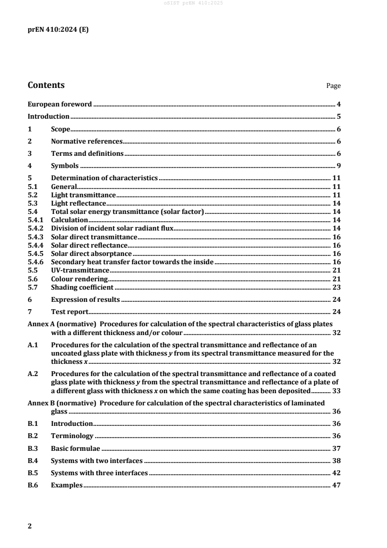
Contents Page
European foreword . 4
Introduction . 5
1 Scope . 6
2 Normative references . 6
3 Terms and definitions . 6
4 Symbols . 9
5 Determination of characteristics . 11
5.1 General. 11
5.2 Light transmittance . 11
5.3 Light reflectance . 14
5.4 Total solar energy transmittance (solar factor) . 14
5.4.1 Calculation . 14
5.4.2 Division of incident solar radiant flux . 14
5.4.3 Solar direct transmittance . 16
5.4.4 Solar direct reflectance . 16
5.4.5 Solar direct absorptance . 16
5.4.6 Secondary heat transfer factor towards the inside . 16
5.5 UV-transmittance . 21
5.6 Colour rendering . 21
5.7 Shading coefficient . 23
6 Expression of results . 24
7 Test report . 24
Annex A (normative) Procedures for calculation of the spectral characteristics of glass plates
with a different thickness and/or colour . 32
A.1 Procedures for the calculation of the spectral transmittance and reflectance of an
uncoated glass plate with thickness y from its spectral transmittance measured for the
thickness x . 32
A.2 Procedures for the calculation of the spectral transmittance and reflectance of a coated
glass plate with thickness y from the spectral transmittance and reflectance of a plate of
a different glass with thickness x on which the same coating has been deposited . 33
Annex B (normative) Procedure for calculation of the spectral characteristics of laminated
glass . 36
B.1 Introduction . 36
B.2 Terminology . 36
B.3 Basic formulae . 37
B.4 Systems with two interfaces . 38
B.5 Systems with three interfaces . 42
B.6 Examples . 47
prEN 410:2024 (E)
Annex C (normative) Procedure for calculation of the spectral characteristics of screen printed
glass . 54
Annex D (normative) Matrix method for non-scattering incoherent optical systems – total solar
energy transmittance for multi-pane glazing units . 55
D.1 The non-scattering incoherent optical system . 55
D.2 Matrix representation . 56
D.3 Modified Matrix Method . 57
D.4 Calculation of the total wavelength dependant absorptances . 58
D.5 Calculation of the total solar integrated absorptances . 60
D.6 Total solar energy transmittance, determination of the g value for multi-pane glazing
units . 61
D.7 Other Considerations . 63
D.8 Examples . 63
Annex E (informative) Modifications to the formulae to permit calculation and declaration of
the luminous and solar properties of BIPV glazing . 74
E.1 General . 74
E.2 Cases to be differentiated . 74
E.3 Test report . 80
Annex F (informative) Example of calculation of colour rendering index . 81
Bibliography . 84
prEN 410:2024 (E)
European foreword
This document (prEN 410:2024) has been prepared by Technical Committee CEN/TC 129 “Glass in
building”, the secretariat of which is held by NBN.
This document is currently submitted to the CEN Enquiry.
This document will supersede EN 410:2011.
In comparison with the previous edition, the following technical modifications have been made:
a) changes to the calculation of the internal heat transfer coefficient for consistency with EN 673:2024;
b) clarification provided that UV transmittance is determined only for the total range and not split into
UVA and UVB;
c) modification to normalized relative spectral distribution of global solar radiation based on 10 nm
wavelength intervals;
d) ambiguity relating to the area-weighting procedure for screen printed glass has been clarified;
e) introduction of a matrix method for non-scattering incoherent optical systems, including multiple
layers;
f) modifications to the formulae to permit calculation and declaration of the luminous and solar
properties of BIPV glazing.
prEN 410:2024 (E)
Introduction
Whilst this document presents the formulae for the exact calculations of the spectral characteristics of
glazing, it does not consider the uncertainty of the measurements necessary to determine the spectral
parameters that are used in the calculations. It should be noted that, for simple glazing systems where
few measurements are required, the uncertainty of the results will be satisfactory if correct
measurements procedures have been followed. When the glazing systems become complex and a large
number of measurements are required to determine the spectral parameters, the uncertainty is
cumulative with the number of measurements and should be considered in the final results.
The term interface used in this document, is considered to be a surface characterized by its transmission
and reflections of light intensities. That is, the interaction with light is incoherent, all phase information
being lost. In the case of thin films (not described in this document), interfaces are characterized by
transmission and reflections of light amplitudes, i.e. the interaction with light is coherent and phase
information is available. Finally, for clarity, a coated interface can be described as having one or more
thin films, but the entire stack of thin films is characterized by its resulting transmission and reflection
of light intensities.
In Annex B, the procedure for the calculation of spectral characteristics of laminated glass makes specific
reference to coated glass. The same procedure can be adopted for filmed glass (e.g. adhesive backed
polymeric film applied to glass).
prEN 410:2024 (E)
1 Scope
This document specifies methods of determining the luminous and solar characteristics of glazing in
buildings. These characteristics can serve as a basis for lighting, heating and cooling calculations of
rooms and permit comparison between different types of glazing.
This document applies both to conventional glazing and to absorbing or reflecting solar-control glazing,
used as vertical or horizontal glazed apertures. The appropriate formulae for single, double and triple
glazing are given. A matrix method is provided as an alternative calculation method.
This document introduces a method to determine the luminous and solar properties of Building-
Integrated Photovoltaic (BIPV) glazing.
This document is accordingly applicable to all transparent materials except those which show
significant transmission in the wavelength region 5 µm to 50 µm of ambient temperature radiation, such
as certain plastic materials.
Materials with light-scattering properties for incident radiation are dealt with as conventional
transparent materials subject to certain conditions (see 5.2).
Angular light and solar properties of glass in building are excluded from this document. However,
research work in this area is summarized in Bibliographic references [1], [2] and [3].
Guidance on the measurement of luminous and spectral properties of glass can be found in the
Bibliography [4].
Vacuum Insulating Glass (VIG) is excluded from the scope of this document. For determination of the
g value of VIG, please refer to ISO 19916-1.
2 Normative references
The following documents are referred to in the text in such a way that some or all of their content
constitutes requirements of this document. For dated references, only the edition cited applies. For
undated references, the latest edition of the referenced document (including any amendments) applies.
EN 673, Glass in building — Determination of thermal transmittance (U value) — Calculation method
EN 12898:2019, Glass in building — Determination of the emissivity
3 Terms and definitions
For the purposes of this document, the following terms and definitions apply.
ISO and IEC maintain terminology databases for use in standardization at the following addresses:
IEC Electropedia: available at http://www.electropedia.org/
ISO Online browsing platform: available at http://www.iso.org/obp/
3.1
light transmittance
fraction of the incident light that is transmitted by the glass
3.2
light reflectance
fraction of the incident light that is reflected by the glass
prEN 410:2024 (E)
3.3
total solar energy transmittance (solar factor)
fraction of the incident solar radiation that is totally transmitted by the glass
3.4
solar direct transmittance
fraction of incident solar radiation that is directly transmitted by the glass
3.5
normal emissivity
ratio, in a direction normal to the surface, of the emissive power of the surface of the glass to the emissive
power of a black body
Note 1 to entry: Normal emissivity is determined in accordance with EN 12898.
3.6
solar direct reflectance
fraction of the incident solar radiation that is reflected by the glass
3.7
ultraviolet transmittance
fraction of the incident UV component of the solar radiation that is transmitted by the glass
3.8
colour rendering index (in transmission)
change in colour of an object as a result of the light being transmitted by the glass
3.9
shading coefficient
ratio of the solar factor of the glass to the solar factor of a reference glass (clear float)
3.10
planar PV module
planar device designed to convert solar radiation into electricity by the photovoltaic effect
Note 1 to entry: The glazing configuration of a planar PV module may be, but is not restricted to, a coated or
uncoated pane of glass, a coated polymer film, a glass-polymer laminate or a glass-polymer-glass laminate. For the
sake of brevity, the term PV module will be understood to mean a planar PV module in Annex E.
3.11
building-integrated photovoltaic (BIPV) glazing
architectural glazing that incorporates a (planar) PV module as one of its panes
Note 1 to entry: In this context, architectural glazing refers to glazed apertures in buildings.
prEN 410:2024 (E)
3.12
optically homogeneous
attribute of glazing with optical properties, which, when determined using a spectrophotometer in
accordance with this European Standard, are independent of the position selected for measurement
Note 1 to entry: Many thin-film PV modules are examples of optically homogeneous glazing.
3.13
optically inhomogeneous
attribute of glazing with optical properties, which, when determined using a spectrophotometer in
accordance with this document, vary significantly (i.e. by an amount greater than measurement
tolerances) on the position selected for measurement
Note 1 to entry: Typically, this refers to areas on a scale of cm that have a visibly different appearance, e.g.
crystalline PV cells surrounded by a transparent embedding material.
3.14
open circuit
OC
with reference to a PV device, an electrical state in which the output electric current is zero
Note 1 to entry: Adapted from 3.4.57 of IEC TS 61836.
3.15
maximum power point
MPP
point on a PV device's current-voltage characteristic where the product of electric current and voltage
yields the maximum electrical power under specified operating conditions
[SOURCE: IEC TS 61836, 3.4.43.3]
3.16
standard test conditions
STC
reference values of in-plane irradiance (GI,ref = 1 000 W/m ), photovoltaic cell junction temperature
(25 °C), and a reference spectral irradiance distribution calculated for air mass = 1,5, used during the
testing of any photovoltaic device
[SOURCE: IEC TS 61836, 3.4.87]
3.17
conversion efficiency
ratio of electric power generated by a PV device per unit area to its incident irradiance
[SOURCE: IEC TS 61836, 3.1.17]
prEN 410:2024 (E)
4 Symbols
Sym. Deutsch/German/Allemand Englisch/English/Anglais Französisch/French/Français
D65 Normlichtart D65 standard illuminant D65 illuminant normalisé D65
UV Ultravioletter ultraviolet radiation rayonnement ultraviolet
Strahlungsbereich
τ Ultravioletter ultraviolet transmittance facteur de transmission de
UV
Transmissionsgrad l'ultraviolet
τ(λ) Spektraler Transmissionsgrad spectral transmittance facteur de transmission
spectrale
ρ(λ) Spektraler Reflexionsgrad spectral reflectance facteur de réflexion spectrale
τ Lichtransmissionsgrad light transmittance facteur de transmission
V
lumineuse
ρ Lichtreflexionsgrad light reflectance facteur de réflexion lumineuse
v
τ direkter Strahlungstrans- solar direct transmittance facteur de transmission directe
e
missionsgrad de l'énergie solaire
ρ direkter Strahlungs- solar direct reflectance facteur de réflexion directe de
e
reflexionsgrad l'énergie solaire
g Gesamtenergiedurchlaß- grad total solar energy facteur de transmission totale
transmittance (solar de l'énergie solaire ou facteur
factor) solaire
R allgemeiner Farbwieder- general colour rendering indice général de rendu des
a
gabeindex index couleurs
D relative spektrale Vertei- lung relative spectral répartition spectrale relative de
λ
der Normlichtart D65 distribution of illuminant l'illuminant normalisé D65
D65
V(λ) spektraler Hellempfindlich- spectral luminous efficacité lumineuse relative
keitsgrad efficiency spectrale
α direkter Strahlungsabsorp solar direct absorptance facteur d'absorption directe de
e
tionsgrad l'énergie solaire
Φ Strahlungsleistung incident solar radiant flux flux énergétique solaire
e
(Strahlungsfluß) incident
q sekundärer Wärmeabgabe- secondary internal heat facteur de réémission
i
grad nach innen transfer factor thermique vers l'intérieur
q sekundärer Wärme- secondary external heat facteur de réémission
e
abgabegrad nach außen transfer factor thermique vers l'extérieur
prEN 410:2024 (E)
Sym. Deutsch/German/Allemand Englisch/English/Anglais Französisch/French/Français
α Anteil der insgesamt proportion of total proportion du rayonnement
elec
absorbierten Solarstrahlung, absorbed solar radiation solaire total absorbé qui est
der als Strom von der PV- that is extracted from the extrait de la surface couverte de
Zellenfläche einer BIPV- PV cell-covered area of a cellules photovoltaïques d'un
Verglasungseinheit abgeführt BIPV glazing unit as vitrage BIPV, sous forme
wird electricity d'électricité
S relative spektrale Vertei- lung relative spectral répartition spectrale relative du
λ
der Sonnenstrahlung distribution of solar rayonnement solaire
radiation
he Wärmeübergangs- koeffizient external heat transfer coefficient d'échange
nach außen coefficient thermique extérieur
h Wärmeübergangs- koeffizient internal heat transfer coefficient d'échange
i
nach innen coefficient thermique intérieur
ε korrigierter Emissionsgrad corrected emissivity émissivité corrigée
εn normaler Emissionsgrad normal emissivity émissivité normale
Λ Wärmedurchlaßkoeffizient thermal conductance conductance thermique
λ Wellenlänge wavelength longueur d'onde
Δλ Wellenlängenintervall wavelength interval intervalle de longueur d'onde
U relative spektrale Vertei- relative spectral répartition spectrale relative du
λ
Lung der UV-Strahlung der distribution of UV in solar rayonnement ultraviolet solaire
Sonne radiation
SC Durchlassfaktor shading coefficient coefficient d’ombrage
normalisierter spektraler spectral normalized flux radiant spectral normalisé
I(λ)
Strahlungsfluß radiant flow
elektrischer Wirkungsgrad photovoltaic conversion efficacité de conversion de
η
mod
eines PV-Moduls efficiency of a PV module puissance du module
photovoltaïque
A Fläche surface area superficie
r Reflexionsgrad an der reflectance on interface facteur de réflexion à l'interface
Oberfläche
CR Deckungsgrad coverage ratio taux de couverture
η elektrischer Wirkungsgrad power conversion efficacité de conversion de
cell,mod
eines hypothetischen PV- efficiency of a hypothetical puissance d'un module
Moduls mit 100 % PV module with 100% cell photovoltaïque hypothétique
Zelldeckungsgrad coverage ratio
prEN 410:2024 (E)
5 Determination of characteristics
5.1 General
The characteristics are determined for quasi-parallel, near normal radiation incidence (see
Bibliography, [4]) using the radiation distribution of illuminant D65 (see Table 1), solar radiation in
accordance with Table 2 and ultraviolet (UV) radiation in accordance with Table 3.
The characteristics are as follows:
the spectral transmittance τ(λ) and the spectral reflectance ρ (λ) in the wavelength range from
300 nm to 2 500 nm;
the light transmittance τ and the light reflectance ρ for illuminant D65;
v v
the solar direct transmittance τ and the solar direct reflectance ρ ;
e e
the total solar energy transmittance (solar factor) g ;
the UV-transmittance τ ;
UV
the general colour rendering index R ;
a
the total shading coefficient, SC.
To characterize glazing, the principal parameters are τ and g; the other parameters are optional to
v
provide additional information.
If the value of a given characteristic is required for different glass thicknesses (in the case of uncoated
glass) or for the same coating applied to different substrates, it can be obtained by calculation (in
accordance with Annex A).
A procedure for the calculation of the spectral characteristics of laminated glass is given in Annex B.
Guidelines on determining the spectral characteristics of screen-printed glass are given in Annex C.
A modified matrix method is provided as an alternative calculation method is given in Annex D.
Modifications to the formulae to permit calculation and declaration of the luminous and solar properties
of BIPV glazing are given in Annex E.
The convention adopted in this document is for the incident radiation to be from left to right. The left
side is also referred to as outside or outdoors, whereas the right side is also referred to as inside or
indoors.
5.2 Light transmittance
The light transmittance τ of the glazing is calculated using the following formula:
v
780 𝑛𝑛𝑛𝑛
∑ 𝐷𝐷 ⋅𝜏𝜏(𝜆𝜆)⋅𝑉𝑉(𝜆𝜆)⋅𝛥𝛥𝜆𝜆
𝜆𝜆
𝜆𝜆=380 𝑛𝑛𝑛𝑛
𝜏𝜏 = (1)
𝑣𝑣 780 𝑛𝑛𝑛𝑛
∑
𝐷𝐷 ⋅𝑉𝑉(𝜆𝜆)⋅𝛥𝛥𝜆𝜆
𝜆𝜆
𝜆𝜆=380 𝑛𝑛𝑛𝑛
where
D
λ is the relative spectral distribution of illuminant D65 (see Bibliography [5]);
τ(λ) is the spectral transmittance of the glazing;
prEN 410:2024 (E)
V(λ) is the spectral luminous efficiency for photopic vision defining the standard observer for
photometry (see Bibliography [5]);
Δλ is the wavelength interval.
Table 1 indicates the values for 𝐷𝐷 ⋅𝑉𝑉(𝜆𝜆)⋅𝛥𝛥𝜆𝜆 for wavelength intervals of 10 nm. The table has been
𝜆𝜆
drawn up in such a way that ∑𝐷𝐷 ⋅𝑉𝑉(𝜆𝜆)⋅𝛥𝛥𝜆𝜆 = 1.
𝜆𝜆
In the case of multiple glazing, the spectral transmittance τ(λ) is calculated from the spectral
transmittances and reflectances of the individual components as follows:
For double glazing:
𝜏𝜏 (𝜆𝜆)⋅𝜏𝜏 (𝜆𝜆)
1 2
𝜏𝜏(𝜆𝜆) = (2)
′
1−𝜌𝜌 (𝜆𝜆)⋅𝜌𝜌 (𝜆𝜆)
where
τ (λ) is the spectral transmittance of the first (outer) pane;
τ (λ) is the spectral transmittance of the second pane;
ρ '(λ) is the spectral reflectance of the first (outer) pane, measured in the direction opposite to
the incident radiation;
ρ (λ) is the spectral reflectance of the second pane, measured in the direction of the incident
radiation.
The above is illustrated in Figure 1.
Key
1 pane 1
2 cavity
3 pane 2
Figure 1 — Transmittance and reflectance in a double glazing insulating glass unit
prEN 410:2024 (E)
For triple glazing:
𝜏𝜏 (𝜆𝜆)⋅𝜏𝜏 (𝜆𝜆)⋅𝜏𝜏 (𝜆𝜆)
1 2 3
( )
𝜏𝜏𝜆𝜆 = (3)
′ ′ 2 ′
( ) ( )
�1−𝜌𝜌 (𝜆𝜆)⋅𝜌𝜌 (𝜆𝜆)�⋅�1−𝜌𝜌 𝜆𝜆⋅𝜌𝜌 𝜆𝜆�−𝜏𝜏 (𝜆𝜆)⋅𝜌𝜌 (𝜆𝜆)⋅𝜌𝜌 (𝜆𝜆)
2 3 3
1 2 2 1
where
τ (λ), τ (λ) ρ '(λ) and ρ (λ) are as explained in Formula (2);
1 2 1 2
τ (λ) is the spectral transmittance of the third pane;
ρ '(λ) is the spectral reflectance of the second pane, measured in the direction opposite to the
incident radiation;
ρ (λ) is the spectral reflectance of the third pane, measured in the direction of the incident
radiation.
The above is illustrated in Figure 2.
Key
1 pane 1
2 cavity 1
3 pane 2
4 cavity 2
5 pane 3
Figure 2 — Transmittance and reflectance in a triple glazing insulating glass unit
For glazing with more than three components, formulae similar to Formulae (2) and (3) are found to
calculate τ(λ) of such glazing from the spectral coefficients of the individual components. As an example,
glazing composed of five components may be treated as follows:
a) first consider the first three components as triple glazing and calculate the spectral characteristics
of this combination;
b) next, run the same procedure for the next two components as double glazing;
c) then calculate τ(λ) for the five-component glazing, considering it as double glazing consisting of the
preceding triple and double glazing (or, alternatively, the methodology in Annex D could be
followed).
The use of an integrating sphere is necessary when light scattering materials are tested. In this case the
size of the sphere and its aperture shall be large enough to collect all possible scattered light and to
obtain fair average values when surface patterns are irregularly distributed.
NOTE Measurement of light scattering glass products is the subject of a round robin test programme under
the responsibility of International Commission on Glass Technical Committee 10. The results of this programme
are expected to include suggestions for improvements in measurement and prediction techniques.
prEN 410:2024 (E)
5.3 Light reflectance
The light reflectance of the glazing ρ is calculated using the following formula:
v
780 𝑛𝑛𝑛𝑛
∑ 𝐷𝐷 ⋅𝜌𝜌(𝜆𝜆)⋅𝑉𝑉(𝜆𝜆)⋅𝛥𝛥𝜆𝜆
𝜆𝜆
𝜆𝜆=380 𝑛𝑛𝑛𝑛
𝜌𝜌 = (4)
𝑣𝑣 780 𝑛𝑛𝑛𝑛
∑ 𝐷𝐷 ⋅𝑉𝑉(𝜆𝜆)⋅𝛥𝛥𝜆𝜆
𝜆𝜆
𝜆𝜆=380 𝑛𝑛𝑛𝑛
where
D , V(λ) and Δλ are as explained in 5.2;
λ
ρ(λ) is the spectral reflectance of the glazing.
In the case of multiple glazing, the spectral reflectance ρ(λ) is calculated from the spectral
transmittances and the spectral reflectances of the individual components as follows.
For double glazing, the external light reflectance of the glazing is calculated as follows:
𝜏𝜏 (𝜆𝜆)⋅𝜌𝜌 (𝜆𝜆)
1 2
𝜌𝜌(𝜆𝜆) =𝜌𝜌 (𝜆𝜆) + (5)
′
1−𝜌𝜌 (𝜆𝜆)⋅𝜌𝜌 (𝜆𝜆)
1 2
where
τ (λ), ρ (λ) and ρ '(λ) are as explained in 5.2;
1 2 1
ρ (λ) is the spectral reflectance of the first (outer) pane, measured in the direction of incident
radiation.
A corresponding formula can also be derived for calculating the internal light reflectance.
For triple glazing, the external light reflectance of the glazing is calculated as follows:
2 ′ 2 2
𝜏𝜏 (𝜆𝜆)⋅𝜌𝜌 (𝜆𝜆)⋅�1−𝜌𝜌 (𝜆𝜆)⋅𝜌𝜌 (𝜆𝜆)�+𝜏𝜏 (𝜆𝜆)⋅𝜏𝜏 (𝜆𝜆)⋅𝜌𝜌 (𝜆𝜆)
1 2 2 3 1 2 3
𝜌𝜌(𝜆𝜆) =𝜌𝜌 + (6)
1 ′ ′ 2 ′
�1−𝜌𝜌 (𝜆𝜆)⋅𝜌𝜌 (𝜆𝜆)�⋅�1−𝜌𝜌 (𝜆𝜆)⋅𝜌𝜌 (𝜆𝜆)�−𝜏𝜏 (𝜆𝜆)⋅𝜌𝜌 (𝜆𝜆)⋅𝜌𝜌 (𝜆𝜆)
2 3 3
1 2 2 1
where
ρ (λ) is the spectral reflectance of the third pane, measured in the direction of the incident
radiation;
τ (λ), τ (λ), ρ (λ), ρ (λ), ρ '(λ) and ρ '(λ) are as defined in 5.2 and 5.3.
1 2 1 2 1 2
A corresponding formula for the internal light reflectance of triple glazing can also be derived.
For glazing with more than three elements, the same method as described in 5.2 is used.
5.4 Total solar energy transmittance (solar factor)
5.4.1 Calculation
The total solar energy transmittance g is calculated as the sum of the solar direct transmittance τ and
e
the secondary heat transfer factor q of the glazing towards the inside (see 5.4.3 and 5.4.6), the latter
i
resulting from heat transfer by convection and longwave IR-radiation of that part of the incident solar
radiation which has been absorbed by the glazing:
𝑔𝑔 =𝜏𝜏 +𝑞𝑞 (7)
𝑒𝑒 𝑖𝑖
5.4.2 Division of incident solar radiant flux
The incident solar radiant flux Φ is divided into the following three parts (see Figure 3):
e
a) the transmitted part, τ Φ ;
e e
b) the reflected part, ρ Φ ;
e e
prEN 410:2024 (E)
c) the absorbed part, α Φ ;
e e
where
τ is the solar direct transmittance (see 5.4.3);
e
ρ is the solar direct reflectance (see 5.4.4);
e
α is the solar direct absorptance (see 5.4.5).
e
Key
1 outer pane
2 inner pane
3 unit incident radiant flux
Figure 3 — Example of division of the incident radiant flux
The relation between the three characteristics is:
𝜏𝜏 +𝜌𝜌 +𝛼𝛼 = 1 (8)
𝑒𝑒 𝑒𝑒 𝑒𝑒
The absorbed part α Φ is subsequently split into two parts, q Φ and q Φ , which are energy transferred
e e i e e e
to the inside and outside respectively:
𝛼𝛼 =𝑞𝑞 +𝑞𝑞 (9)
𝑒𝑒 𝑖𝑖 𝑒𝑒
where
q is the secondary heat transfer factor of the glazing towards the inside;
i
q is the secondary heat transfer factor of the glazing towards the outside.
ei
prEN 410:2024 (E)
5.4.3 Solar direct transmittance
The solar direct transmittance τ of the glazing is calculated using the following formula:
e
2500 𝑛𝑛𝑛𝑛
∑ 𝑆𝑆 ⋅𝜏𝜏(𝜆𝜆)⋅𝛥𝛥𝜆𝜆
𝜆𝜆
𝜆𝜆=300 𝑛𝑛𝑛𝑛
𝜏𝜏 = (10)
𝑒𝑒 2500 𝑛𝑛𝑛𝑛
∑ 𝑆𝑆 ⋅𝛥𝛥𝜆𝜆
𝜆𝜆
𝜆𝜆=300 𝑛𝑛𝑛𝑛
where
S is the relative spectral distribution of the solar radiation (see Table 2);
λ
τ(λ) is the spectral transmittance of the glazing;
Δλ is the wavelength interval.
In the case of multiple glazing, the spectral transmittance τ(λ) is calculated in accordance with 5.2.
The relative spectral distribution, S , used to calculate the solar direct transmittance is derived from CIE
λ
85 [6].
The corresponding values S Δ are given in Table 2. The table was drawn up in such a way that
λ λ
∑
𝑆𝑆𝛥𝛥𝜆𝜆 = 1.
𝜆𝜆
NOTE Contrary to real situations, it is always assumed, for simplification, that the spectral distribution of the
solar radiation (see Table 2) is not dependent upon atmospheric conditions (e.g. dust, mist, moisture content) and
that the solar radiation strikes the glazing as a collimated beam and at normal incidence. The resulting errors are
very small.
5.4.4 Solar direct reflectance
The solar direct reflectance ρ of the glazing is calculated using the following formula:
e
2500 𝑛𝑛𝑛𝑛
∑ 𝑆𝑆 ⋅𝜌𝜌(𝜆𝜆)⋅𝛥𝛥𝜆𝜆
𝜆𝜆
𝜆𝜆=300 𝑛𝑛𝑛𝑛
𝜌𝜌 = (11)
𝑒𝑒 2500 𝑛𝑛𝑛𝑛
∑
𝑆𝑆 ⋅𝛥𝛥𝜆𝜆
𝜆𝜆
𝜆𝜆=300 𝑛𝑛𝑛𝑛
where
S is the relative spectral distribution of the solar radiation (see Table 2);
λ
ρ(λ) is the spectral reflectance of the glazing;
Δλ is the wavelength interval.
In the case of multiple glazing, the spectral reflectance ρ(λ) is calculated in accordance with 5.3.
5.4.5 Solar direct absorptance
The solar direct absorptance α is calculated from Formula (8) in 5.4.2.
e
5.4.6 Secondary heat transfer factor towards the inside
5.4.6.1 Boundary conditions
For the calculation of the secondary heat transfer factor towards the inside, q, the heat transfer
i
coefficients of the glazing towards the outside, h , and towards the inside, h are needed. These values
e i
mainly depend on the position of the glazing, wind velocity, inside and outside temperatures and
furthermore on the temperature of the two external glazing surfaces.
As the purpose of this document is to provide basic information on the performance of glazing,
conventional conditions have been stated for simplicity:
a) position of the glazing: vertical;
prEN 410:2024 (E)
b) outside surface: wind velocity: approximately 4 m/s, corrected emissivity = 0,837;
c) inside surface: natural convection, emissivity optional;
d) air spaces are unventilated.
Under these conventional, average conditions, standard values for h and h are obtained:
e i
ℎ = 25𝑊𝑊⁄(𝑚𝑚 ⋅𝐾𝐾)
𝑒𝑒
ℎ =ℎ +ℎ (12)
𝑖𝑖 𝑟𝑟 𝑐𝑐
where
h is the internal radiative heat transfer coefficient;
r
h is the internal convective heat transfer coefficient.
c
For the purposes of this document, the internal radiative heat transfer coefficient for uncoated soda lime
glass surfaces is 4,8 W/(m .K), rounded to one decimal place.
If the internal surface of the glass has a lower emissivity, the internal radiative heat transfer coefficient
is given by:
= 4⋅𝜀𝜀 .𝜎𝜎 .𝑇𝑇 (13)
ℎ
𝑟𝑟 𝑠𝑠
where
ε is the corrected emissivity of the coated surface;
−8 2 4
σ is Stefan-Boltzmann's constant, 5,67 × 10 W/(m ·K );
T is the mean temperature of the internal surface of the glass (K).
s
This is only applicable if there is no condensation on the coated surface. A procedure for determining
the corrected emissivity of a coating is given in EN 12898:2019.
The value of h is 2,5 W/(m ·K) for free convection for horizontal heat flow.
c
For vertical soda lime glass surfaces and free convection
⁄( )
ℎ = 4,8 + 2,5 = 7,3𝑊𝑊 𝑚𝑚 ⋅𝐾𝐾 (14)
𝑖𝑖
which is standardized for the purposes of comparison of U values.
For uncoated soda lime silicate glass, e = 0,837 and h = 7,3 W/(m .K).
i
With reasonable confidence the same value may be used for uncoated borosilicate glass, alkaline earth
silicate glass, alumino silicate glass and glass ceramics.
The corrected emissivity shall be defined and measured in accordance with EN 12898:2019.
NOTE Values lower than 0,837 for e (due to surface coatings with higher reflectance in the far infra-red) are
only to be taken into account if condensation on the coated surface can be excluded.
prEN 410:2024 (E)
5.4.6.2 Single glazing
The secondary internal heat transfer factor, q , of single glazing is calculated using the following formula:
i
ℎ
𝑖𝑖
𝑞𝑞 =𝛼𝛼 ⋅ (15)
𝑖𝑖 𝑒𝑒
ℎ +ℎ
𝑒𝑒
𝑖𝑖
where
α is the solar direct absorptance in accordance with 5.4.5;
e
h and h are the heat transfer coefficients towards the outside and inside respectively in
e i
accordance with 5.4.6.1.
5.4.6.3 Double glazing
The secondary internal heat transfer factor, qi, of double glazing is calculated using the following
formula:
𝛼𝛼 +𝛼𝛼 𝛼𝛼
𝑒𝑒1 𝑒𝑒2 𝑒𝑒2
� + �
ℎ 𝛬𝛬
𝑒𝑒
𝑞𝑞 = (16)
𝑖𝑖
1 1 1
� + + �
ℎ ℎ 𝛬𝛬
𝑒𝑒
𝑖𝑖
where
h and h are the heat transfer coefficients towards the outside and inside respectively in
e i
accordance with 5.4.6.1;
α is the solar direct absorptance of the outer pane within the double glazing;
e1
α is the solar direct absorptance of the second pane within the double glazing;
e2
Λ is the thermal conductance between the outer surface and the innermost surface of the
double glazing (see Figure 4).
α and α are calculated as follows:
e1 e2
′
𝛼𝛼 (𝜆𝜆)⋅𝜏𝜏 (𝜆𝜆)⋅𝜌𝜌 (𝜆𝜆)
2500 𝑛𝑛𝑛𝑛 1 1 2
∑ � ( ) �
𝑆𝑆 ⋅𝛼𝛼 𝜆𝜆+ ⋅𝛥𝛥𝜆𝜆
𝜆𝜆 1
𝜆𝜆=300 𝑛𝑛𝑛𝑛 ′
1−𝜌𝜌 (𝜆𝜆)⋅𝜌𝜌 (𝜆𝜆)
1 2
𝛼𝛼 = (17)
𝑒𝑒1 2500 𝑛𝑛𝑛𝑛
∑ 𝑆𝑆 ⋅𝛥𝛥𝜆𝜆
𝜆𝜆
𝜆𝜆=300 𝑛𝑛𝑛𝑛
𝛼𝛼 (𝜆𝜆)⋅𝜏𝜏 (𝜆𝜆)
2500 𝑛𝑛𝑛𝑛 2 1
∑ 𝑆𝑆 ⋅� �⋅𝛥𝛥𝜆𝜆
𝜆𝜆
𝜆𝜆=300 𝑛𝑛𝑛𝑛 ′
1−𝜌𝜌 (𝜆𝜆)⋅𝜌𝜌 (𝜆𝜆)
𝛼𝛼 = (18)
𝑒𝑒2 2500 𝑛𝑛𝑛𝑛
∑ 𝑆𝑆 ⋅𝛥𝛥𝜆𝜆
𝜆𝜆
𝜆𝜆=300 𝑛𝑛𝑛𝑛
where
(λ) is the spectral direct absorptance of the outer pane, measured in the direction of the
α1
incident radiation, given by the formula:
𝛼𝛼 (𝜆𝜆) = 1−𝜏𝜏 (𝜆𝜆)−𝜌𝜌 (𝜆𝜆) (19)
1 1 1
α '(λ) is the spectral direct absorptance of the outer pane, measured in the opposite direction
to the incident radiation, given by the formula:
′ ′
𝛼𝛼 (𝜆𝜆) = 1−𝜏𝜏 (𝜆𝜆)−𝜌𝜌 (𝜆𝜆) (20)
1 1
(λ) is the spectral direct absorptance of the second pane, measured in the direction of the
α2
incident radiation, given by the formula:
prEN 410:2024 (E)
𝛼𝛼 (𝜆𝜆) = 1−𝜏𝜏 (𝜆𝜆)−𝜌𝜌 (𝜆𝜆) (21)
2 2
S and Δλ are as defined in 5.4.3;
λ
τ (λ), ρ (λ) and ρ '(λ) are as defined in 5.2.
1 2 1
The thermal conductance Λ shall be determined by the calculation method in accordance with EN 673,
whenever possible. Where this is not possible, measuring methods in accordance with EN 674 or EN 675
should be used.
Key
1 pane 1
2 pane 2
3 outside
4 inside
Figure 4 — Illustration of the meaning of thermal conductance Λ
5.4.6.4 Triple glazing
The secondary internal heat transfer factor of triple glazing, q , is calculated using the following formula:
i
𝛼𝛼 𝛼𝛼 +𝛼𝛼 𝛼𝛼 +𝛼𝛼 +𝛼𝛼
𝑒𝑒3 𝑒𝑒3 𝑒𝑒2 𝑒𝑒3 𝑒𝑒2 𝑒𝑒1
� + + �
𝛬𝛬 𝛬𝛬 ℎ
23 12 𝑒𝑒
𝑞𝑞 = (22)
𝑖𝑖
1 1 1 1
� + + + �
ℎ ℎ 𝛬𝛬 𝛬𝛬
𝑒𝑒 12 23
𝑖𝑖
where
α is the solar direct absorptance of the outer pane within the triple glazing;
e1
is the solar direct absorptance of the second pane within the triple glazing;
αe2
α is the solar direct absorptance of the third pane within the triple glazing;
e3
h and h are the heat transfer coefficients towards the outside and inside respectively in
e i
accordance with 5.4.6.1;
Λ is the thermal conductance between the outer surface of the first pane and the centre of
the second pane (see Figure 5);
Λ is the thermal conductance between the centre of the second pane and the innermost
surface of the third pane (see Figure 5).
prEN 410:2024 (E)
Key
1 pane 1
2 pane 2
3 pane 3
4 outside
5 inside
Figure 5 — Illustration of the meaning of the thermal conductances Λ and Λ
12 23
α , α and α are calculated as follows:
e1 e2 e3
′ ′ 2 ′
( ) ( ) ( ) ( ) ( )
𝛼𝛼 𝜆𝜆⋅𝜏𝜏 𝜆𝜆⋅𝜌𝜌 𝜆𝜆⋅�1−𝜌𝜌 𝜆𝜆⋅𝜌𝜌 𝜆𝜆�+𝜏𝜏 (𝜆𝜆)⋅𝜏𝜏 (𝜆𝜆)⋅𝛼𝛼 (𝜆𝜆)⋅𝜌𝜌 (𝜆𝜆)
1 2 3 1 3
1 2 2 1
2500 𝑛𝑛𝑛𝑛
∑ ( )
𝑆𝑆 ⋅�𝛼𝛼 𝜆𝜆+ �⋅𝛥𝛥𝜆𝜆
𝜆𝜆=300 𝑛𝑛𝑛𝑛 𝜆𝜆 ′ ′ 2 ′
�1−𝜌𝜌 (𝜆𝜆)⋅𝜌𝜌 (𝜆𝜆)�⋅�1−𝜌𝜌 (𝜆𝜆)⋅𝜌𝜌 (𝜆𝜆)�−𝜏𝜏 (𝜆𝜆)⋅𝜌𝜌 (𝜆𝜆)⋅𝜌𝜌 (𝜆𝜆)
2 3 3
1 2 2 1
𝛼𝛼 = (23)
𝑒𝑒1 2500 𝑛𝑛𝑛𝑛
∑
𝑆𝑆 ⋅𝛥𝛥𝜆𝜆
𝜆𝜆
𝜆𝜆=300 𝑛𝑛𝑛𝑛
′ ′
𝜏𝜏 (𝜆𝜆)⋅𝛼𝛼 (𝜆𝜆)⋅�1−𝜌𝜌 (𝜆𝜆)⋅𝜌𝜌 (𝜆𝜆)�+𝜏𝜏 (𝜆𝜆)⋅𝜏𝜏 (𝜆𝜆)⋅𝛼𝛼 (𝜆𝜆)⋅𝜌𝜌 (𝜆𝜆)
1 2 2 3 1 2 2 3
2500 𝑛𝑛𝑛𝑛
∑ 𝑆𝑆 ⋅� �⋅𝛥𝛥𝜆𝜆
𝜆𝜆
𝜆𝜆=300 𝑛𝑛𝑛𝑛 ′ ′ 2 ′
( ) ( ) ( )
�1−𝜌𝜌 𝜆𝜆⋅𝜌𝜌 (𝜆𝜆)�⋅�1−𝜌𝜌 𝜆𝜆⋅𝜌𝜌 𝜆𝜆�−𝜏𝜏 (𝜆𝜆)⋅𝜌𝜌 (𝜆𝜆)⋅𝜌𝜌 (𝜆𝜆)
2 3 3
1 2 2 1
𝛼𝛼 = (24)
𝑒𝑒2 2500 𝑛𝑛𝑛𝑛
∑ 𝑆𝑆 ⋅𝛥𝛥𝜆𝜆
𝜆𝜆
𝜆𝜆=300 𝑛𝑛𝑛𝑛
𝜏𝜏 (𝜆𝜆)⋅𝜏𝜏 (𝜆𝜆)⋅𝛼𝛼 (𝜆𝜆)
2500 𝑛𝑛𝑛𝑛 1 2 3
∑ 𝑆𝑆 ⋅� �⋅𝛥𝛥𝜆𝜆
𝜆𝜆
𝜆𝜆=300 𝑛𝑛𝑛𝑛 ′ ′ 2 ′
�1−𝜌𝜌 (𝜆𝜆)⋅𝜌𝜌 (𝜆𝜆)�⋅�1−𝜌𝜌 (𝜆𝜆)⋅𝜌𝜌 (𝜆𝜆)�−𝜏𝜏 (𝜆𝜆)⋅𝜌𝜌 (𝜆𝜆)⋅𝜌𝜌 (𝜆𝜆)
2 3 3
1 2 2 1
𝛼𝛼 = (25)
𝑒𝑒3 2500 𝑛𝑛𝑛𝑛
∑
𝑆𝑆 ⋅𝛥𝛥𝜆𝜆
𝜆𝜆
𝜆𝜆=300 𝑛𝑛𝑛𝑛
where
α (λ), α '(λ) and α (λ) are as defined in 5.4.6.3;
1 1 2
α '(λ) is the spectral direct absorptance of the second pane, measured in the opposite direction
to the incident radiation, given by the formula:
′ ′
𝛼𝛼 (𝜆𝜆) = 1−𝜏𝜏 (𝜆𝜆)−𝜌𝜌 (𝜆𝜆) (26)
2 2 2
τ (λ) is the spectral transmittance of the second pane;
ρ '(λ) is the spectral reflectance of the second pane, measured in the opposite direction for the
incident radiation;
α (λ) is the spectral direct absorptance of the third pane, measured in the direction of the
incident radiation, given by the formula:
𝛼𝛼 (𝜆𝜆) = 1−𝜏𝜏 (𝜆𝜆)−𝜌𝜌 (𝜆𝜆) (27)
3 3 3
S and Δλ are as defined in 5.4.3;
λ
τ (λ) is the spectral transmittance of the third pane;
prEN 410:2024 (E)
ρ '(λ) is the spectral reflectance of the third pane, measured in the opposite direction for the
incident radiation.
The thermal conductances Λ and Λ are determined in accordance with 5.4.6.3.
12 23
5.4.6.5 Quadruple glazing
The secondary internal heat transfer factor of quadruple glazing can be determined by reference to the
g value calculation in Annex D.
5.5 UV-transmittance
A standard relative spectral distribution for the UV part of the global solar radiation, U , is given (see
λ
Bibliography, [7]). Table 3 gives the values of UΔλ for wavelength intervals of 5 nm in the UV range.
λ
∑
The table has been drawn up with relative values in such a way that 𝑈𝑈 ⋅𝛥𝛥𝜆𝜆 = 1 for the total UV range.
𝜆𝜆
The UV-transmittance τ is calculated as follows:
uv
380𝑛𝑛𝑛𝑛
∑ 𝑈𝑈 𝜏𝜏(𝜆𝜆)𝛥𝛥𝜆𝜆
𝜆𝜆
𝜆𝜆=300𝑛𝑛𝑛𝑛
𝜏𝜏 = (28)
𝑢𝑢𝑣𝑣 380𝑛𝑛𝑛𝑛
∑ 𝑈𝑈 𝛥𝛥𝜆𝜆
𝜆𝜆
𝜆𝜆=300𝑛𝑛𝑛𝑛
where
τ(λ) is the spectral direct transmittance of the glazing (see 5.2);
U is the relative distribution of the UV part of global solar radiation;
λ
Δλ is the wavelength interval.
NOTE If statements are made about the UV transmission of glazing, in most cases it is sufficient to give τ , th
...