

oSIST prEN 14509-4:2026
(Main)Factory-made double skin metal faced insulating sandwich panels - Part 4: Test methods for fixing of panels to substructure and for determining restraining effect on substructure
- Abstract
This document specifies test methods for determination of characteristics for fixing of factory-made double skin metal faced insulating sandwich panels (hereafter referred to as sandwich panels) to substructure and for stabilization of substructure. Sandwich panels are used for both self-supporting and structural applications in roofs, in external and internal walls (including partitions) and in ceilings in buildings as well as those in cold store applications.
- Status
- Not Published
- Public Enquiry End Date
- 09-Nov-2026
- Technical Committee
- IKER - Ceramics
- Current Stage
- 4020 - Public enquire (PE) (Adopted Project)
- Start Date
- 08-Sep-2026
- Due Date
- 26-Jan-2027

oSIST prEN 14509-4:2026 is a draft European Standard from CEN for factory-made double skin metal faced insulating sandwich panels. It specifies test methods for fixing these panels to substructure and for determining the restraining effect on the supporting structure. The document is for engineers, manufacturers, test laboratories and specifiers who need to measure fixing resistance and stiffness for roofs, walls, ceilings and cold store applications.
What does oSIST prEN 14509-4:2026 specify?
oSIST prEN 14509-4:2026 specifies how to test the characteristics of sandwich panels when they are fixed to a supporting structure and when they help stabilize that structure. It covers both the fixing performance itself and the restraining effect the panel has on the member it is attached to.
Clause 1 sets the scope for self-supporting and structural applications in roofs, external and internal walls, partitions, ceilings and cold store applications. Clause 4 covers resistance of fixings, and Clause 5 covers the parameters needed to determine restraining effect. Clause 3 provides the terms, symbols and abbreviations used throughout the document.
What are the key requirements of oSIST prEN 14509-4:2026?
Clause 4 treats fixing resistance as a property of the panel-fixing system, not of the fastener alone or the supporting structure. In practice, that means the test and the declaration need to focus on the failure modes in the sandwich panel, while fastener failure and support failure are handled separately.
Fixing families, specimen choice and reporting
Clause 4.1 allows a test series to represent a family of panels and one type or group of fasteners, but the weakest relevant combination within that family has to be tested. The panel family is defined by items such as face profiling, core material, longitudinal joint type, thicknesses and adhesive type, while the fastener group is defined by the fastener, washer and any load spreading component. This matters because a declaration of resistance only applies within the family and fixing configuration actually tested.
Clause 4.1.2 sets out what the test report must record, including the specimen build-up, fixing geometry, test arrangement, cycles, failure mode, load-deflection curves, material properties and any deviations. That gives traceability for later design use, audit or certification.
Tensile resistance of visible fixings
Clause 4.2.2 measures tensile resistance of visible fixings mainly as pull-through failure in the face. The document requires both static and cyclic loading, with at least three static tests at the minimum and maximum panel thickness, and cyclic testing at 5 000 cycles. The cyclic part matters because wind-gust-type effects can reduce fixing resistance in service.
The test result is adjusted to nominal material properties before characteristic values are derived. In practice, the manufacturer or laboratory has to measure the relevant face and core properties from the same batch or document the correction factors used. Clause 4.2.2.6 also permits an alternative no-core test for visible fixings, but only when it gives the lowest tensile resistance and with the stated reduction factor.
Tensile resistance of hidden fixings
Clause 4.2.3 applies the same general approach to hidden fixings, but the joint, load spreading component and local panel failure modes also become part of the evaluation. The test arrangement has to keep the joint in the middle of the specimen and measure displacements beside the joint as well as at the fixing.
This matters in practice because hidden fixings are more sensitive to joint geometry and load transfer details than visible fixings. The calculated adjustment also has to account for face material, core compression strength, core shear strength and, where relevant, the load spreading component.
Shear resistance of fixings
Clause 4.3 determines shear resistance for both visible and hidden fixings. The visible-fixing test loads the fixing until the face shows local bearing deformation or hole elongation, and the result is the characteristic 5 % fractile of the adjusted values.
For users, this is the test to rely on when the concern is sideways load transfer rather than pull-through. The clause also gives specimen sizes, loading rates and the need to document the failure mode and load-displacement curve.
Full-scale alternative for hidden fixings
Clause 4.4 offers a full-scale alternative for tensile resistance of hidden fixings. It uses complete panels, static tests and a defined cyclic loading history, with support reactions and fixing-point forces measured so the resistance of the fixing point can be derived from the full assembly.
This alternative is useful when the small-scale specimen may not capture the interaction between joint, support and panel flexibility well enough. Clause 4.4.7 then combines the adjusted static and cyclic results to determine the declared resistance.
Shortened programme and safety factor
Clause 4.5 allows a shortened test programme only under the conditions referenced from prEN 14509-3:2026. It also gives specific reuse conditions for certain PU and MW core changes, provided the mechanical properties remain at least equal to the prior assessment.
Clause 4.6 sets the material safety factor for ultimate limit state design of fixing to substructure at γM = 1,33. In practice, this links the test result to design use.
Restraining effect and stiffness for support design
Clause 5 addresses the restraining effect that sandwich panels provide to supporting members in structural class II. The document gives methods for rotational spring stiffness and shear stiffness, and it says the rules apply to PU, XPS/EPS and MW panels.
Clause 5.2.2 defines a test method for rotational stiffness using constant surface load on the panel and rotation of the supporting member, with at least three tests at each of the minimum and maximum panel thicknesses. Clause 5.2.3 sets conditions under which calculated stiffness values may be used, including limits on core modulus, compression strength, fastener layout, washer size and panel overhang. Clause 5.3 gives the shear stiffness method for lateral restraint and limits the tabulated fastening factors to steel-faced sandwich panels on steel supports.
What terms does oSIST prEN 14509-4:2026 define?
- Sandwich panel - a building product with two metal faces bonded on either side of a thermally insulating core so the three parts act compositely under load.
- Fixing - the mechanical connection between the sandwich panel and the supporting structure, usually using one or more fasteners.
- Visible fixing - a fixing where the fasteners are visible on the face and pass through both faces and the core.
- Hidden fixing - a fixing placed in the longitudinal joint of adjacent panels, with one or more fasteners and sometimes a load spreading component.
- Load spreading component - a flat or profiled metal part that distributes fastener load into the panel.
- Rotational spring stiffness - the rotational stiffness used to describe the joint between the sandwich panel and the supporting member.
- PU, MW, EPS and XPS - PU means rigid polyurethane foam, MW means mineral wool, EPS means expanded polystyrene, and XPS means extruded polystyrene foam.
Who uses oSIST prEN 14509-4:2026?
oSIST prEN 14509-4:2026 is used by sandwich panel manufacturers who need to declare fixing resistance and restraint properties. It is also used by test laboratories carrying out type tests, by fastener and load-spreader suppliers who need evidence for their components, and by designers of roofs, façades, partitions and cold store linings who need support data for structural calculations.
Quality managers and certification bodies use it to check that the declared fixing values come from the right test method and specimen family. Buyers and specifiers use it when they need to compare products on the basis of tested fixing performance rather than general product descriptions.
Which standards are used with oSIST prEN 14509-4:2026?
| Standard | What it contributes |
|---|---|
| EN 1993-1-3:2024 | Base design rules for cold-formed members and sheeting, and the stiffness framework used in Clause 5. |
| prEN 14509-3:2026 | Statistical evaluation, adjustment rules and related test principles for sandwich panels. |
| EN 1990-1 | Basis of structural design used when the restraining effect is applied in design. |
| EAD 330047-01-0602:2016 | Alternative test approach for visible fixings and the referenced fastening screw assessment route. |
| EN 10204 | Inspection documents for load spreading components. |
| EN 13165 | Core-change conditions for PU panels with covered blowing agents. |
| prEN 14509-5:2026 | Design methods and the safety-factor context for fixing resistance. |
What does the oSIST prEN 14509-4:2026 document contain?
oSIST prEN 14509-4:2026 contains test arrangements, specimen requirements, loading procedures and result-evaluation rules for visible fixings, hidden fixings and shear resistance. It also includes a full-scale alternative method for hidden fixings and procedures for shortened testing in defined cases.
The document uses figures for the visible-fixing, hidden-fixing, full-scale and stiffness test set-ups, and tables for cyclic load history, stiffness parameters and fastening stiffness factors. It also provides formulas for adjusted results, characteristic values, rotational stiffness and shear stiffness, which makes it usable for testing, design checks, product declarations and technical audits.
Get Certified
Connect with accredited certification bodies for this standard

DIBt (Deutsches Institut für Bautechnik)
German Institute for Building Technology.
DIN CERTCO
DIN Group product certification.

Aboma Certification B.V.
Specialized in construction, metal, and transport sectors.
Sponsored listings
Frequently Asked Questions
oSIST prEN 14509-4:2026 is a draft published by the Slovenian Institute for Standardization (SIST). Its full title is "Factory-made double skin metal faced insulating sandwich panels - Part 4: Test methods for fixing of panels to substructure and for determining restraining effect on substructure". This standard covers: This document specifies test methods for determination of characteristics for fixing of factory-made double skin metal faced insulating sandwich panels (hereafter referred to as sandwich panels) to substructure and for stabilization of substructure. Sandwich panels are used for both self-supporting and structural applications in roofs, in external and internal walls (including partitions) and in ceilings in buildings as well as those in cold store applications.
This document specifies test methods for determination of characteristics for fixing of factory-made double skin metal faced insulating sandwich panels (hereafter referred to as sandwich panels) to substructure and for stabilization of substructure. Sandwich panels are used for both self-supporting and structural applications in roofs, in external and internal walls (including partitions) and in ceilings in buildings as well as those in cold store applications.
oSIST prEN 14509-4:2026 is classified under the following ICS (International Classification for Standards) categories: 91.100.60 - Thermal and sound insulating materials. The ICS classification helps identify the subject area and facilitates finding related standards.
oSIST prEN 14509-4:2026 is available in PDF format for immediate download after purchase. The document can be added to your cart and obtained through the secure checkout process. Digital delivery ensures instant access to the complete standard document.
Standards Content (Sample)
SLOVENSKI STANDARD
01-november-2026
Tovarniško izdelane izolacijske sendvič plošče z obojestranskim kovinskim
oplaščenjem - 4. del: Preskusne metode za pritrjevanje plošč na podkonstrukcijo
in za ugotavljanje učinka zadrževanja na podkonstrukcijo
Factory-made double skin metal faced insulating sandwich panels - Part 4: Test methods
for fixing of panels to substructure and for determining restraining effect on substructure
Werkmäßig hergestellte Sandwich-Elemente mit beidseitigen Metalldeckschichten - Teil
4: Prüfverfahren zur Befestigung von Paneelen an der Unterkonstruktion und zur
Bestimmung der Rückhaltewirkung auf die Unterkonstruktion
Panneaux sandwichs isolants à deux parements métalliques manufacturés - Partie 4 :
Méthodes d'essai pour l'assemblage des panneaux à la structure support et pour
déterminer l'effet de maintien de la structure support
Ta slovenski standard je istoveten z: prEN 14509-4
ICS:
91.100.60 Materiali za toplotno in Thermal and sound insulating
zvočno izolacijo materials
2003-01.Slovenski inštitut za standardizacijo. Razmnoževanje celote ali delov tega standarda ni dovoljeno.
DRAFT
EUROPEAN STANDARD
NORME EUROPÉENNE
EUROPÄISCHE NORM
August 2026
ICS 91.100.60
English Version
Factory-made double skin metal faced insulating sandwich
panels - Part 4: Test methods for fixing of panels to
substructure and for determining restraining effect on
substructure
Panneaux sandwichs isolants à deux parements Werkmäßig hergestellte Sandwich-Elemente mit
métalliques manufacturés - Partie 4 : Méthodes d'essai beidseitigen Metalldeckschichten - Teil 4:
pour l'assemblage des panneaux à la structure support Prüfverfahren zur Befestigung von Paneelen an der
et pour déterminer l'effet de maintien de la structure Unterkonstruktion und zur Bestimmung der
support Rückhaltewirkung auf die Unterkonstruktion
This draft European Standard is submitted to CEN members for enquiry. It has been drawn up by the Technical Committee
CEN/TC 128.
If this draft becomes a European Standard, CEN members are bound to comply with the CEN/CENELEC Internal Regulations
which stipulate the conditions for giving this European Standard the status of a national standard without any alteration.
This draft European Standard was established by CEN in three official versions (English, French, German). A version in any other
language made by translation under the responsibility of a CEN member into its own language and notified to the CEN-CENELEC
Management Centre has the same status as the official versions.
CEN members are the national standards bodies of Austria, Belgium, Bulgaria, Croatia, Cyprus, Czech Republic, Denmark, Estonia,
Finland, France, Germany, Greece, Hungary, Iceland, Ireland, Italy, Latvia, Lithuania, Luxembourg, Malta, Netherlands, Norway,
Poland, Portugal, Republic of North Macedonia, Romania, Serbia, Slovakia, Slovenia, Spain, Sweden, Switzerland, Türkiye and
United Kingdom.
Recipients of this draft are invited to submit, with their comments, notification of any relevant patent rights of which they are
aware and to provide supporting documentation.
Warning : This document is not a European Standard. It is distributed for review and comments. It is subject to change without
notice and shall not be referred to as a European Standard.
EUROPEAN COMMITTEE FOR STANDARDIZATION
COMITÉ EUROPÉEN DE NORMALISATION
EUROPÄISCHES KOMITEE FÜR NORMUNG
CEN-CENELEC Management Centre: Rue de la Science 23, B-1040 Brussels
© 2026 CEN All rights of exploitation in any form and by any means reserved Ref. No. prEN 14509-4:2026 E
worldwide for CEN national Members.
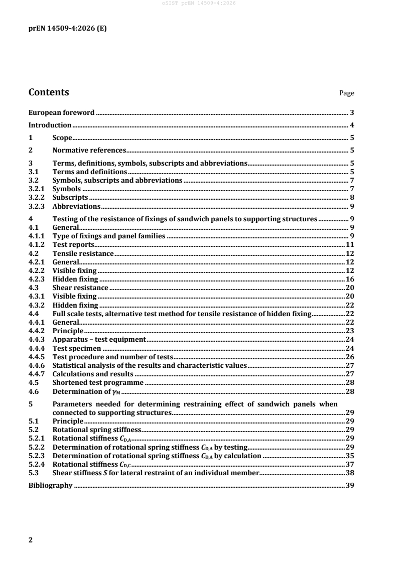
Contents Page
European foreword . 3
Introduction . 4
1 Scope . 5
2 Normative references . 5
3 Terms, definitions, symbols, subscripts and abbreviations . 5
3.1 Terms and definitions . 5
3.2 Symbols, subscripts and abbreviations . 7
3.2.1 Symbols . 7
3.2.2 Subscripts . 8
3.2.3 Abbreviations . 9
4 Testing of the resistance of fixings of sandwich panels to supporting structures . 9
4.1 General. 9
4.1.1 Type of fixings and panel families . 9
4.1.2 Test reports . 11
4.2 Tensile resistance . 12
4.2.1 General. 12
4.2.2 Visible fixing . 12
4.2.3 Hidden fixing . 16
4.3 Shear resistance . 20
4.3.1 Visible fixing . 20
4.3.2 Hidden fixing . 22
4.4 Full scale tests, alternative test method for tensile resistance of hidden fixing . 22
4.4.1 General. 22
4.4.2 Principle . 23
4.4.3 Apparatus – test equipment . 24
4.4.4 Test specimen . 24
4.4.5 Test procedure and number of tests . 26
4.4.6 Statistical analysis of the results and characteristic values . 27
4.4.7 Calculations and results . 27
4.5 Shortened test programme . 28
4.6 Determination of γ . 28
M
5 Parameters needed for determining restraining effect of sandwich panels when
connected to supporting structures . 29
5.1 Principle . 29
5.2 Rotational spring stiffness . 29
5.2.1 Rotational stiffness C . 29
D,A
5.2.2 Determination of rotational spring stiffness C by testing . 29
D,A
5.2.3 Determination of rotational spring stiffness CD,A by calculation . 35
5.2.4 Rotational stiffness C . 37
D,C
5.3 Shear stiffness S for lateral restraint of an individual member . 38
Bibliography . 39
European foreword
This document (prEN 14509-4:2026) has been prepared by Technical Committee CEN/TC 128 “Roof
covering products for discontinuous laying and products for wall cladding”, the secretariat of which is
held by NBN.
This document is currently submitted to the CEN Enquiry.
Introduction
This document gives testing procedures for determining the strength of fixing the panels to
substructures and stabilization of substructures.
1 Scope
This document specifies test methods for determination of characteristics for fixing of factory-made
double skin metal faced insulating sandwich panels (hereafter referred to as sandwich panels) to
substructure and for stabilization of substructure. Sandwich panels are used for both self-supporting
and structural applications in roofs, in external and internal walls (including partitions) and in ceilings
in buildings as well as those in cold store applications.
2 Normative references
The following documents are referred to in the text in such a way that some or all of their content
constitutes requirements of this document. For dated references, only the edition cited applies. For
undated references, the latest edition of the referenced document (including any amendments) applies.
EN 1993-1-3:2024, Eurocode 3 — Design of steel structures — Part 1-3: Cold-formed members and
sheeting
prEN 14509-3:2026 Factory-made double skin metal faced insulating sandwich panels — Part 3: Test
methods for determining mechanical strength, building physical behaviour and durability
3 Terms, definitions, symbols, subscripts and abbreviations
3.1 Terms and definitions
For the purposes of this document, the following terms and definitions apply.
ISO and IEC maintain terminology databases for use in standardization at the following addresses:
— ISO Online browsing platform: available at https://www.iso.org/obp/
— IEC Electropedia: available at https://www.electropedia.org/
3.1.1
bond
bonding
adhesion between the face(s) and the core normally provided by an adhesive
3.1.2
ceiling
covering over an internal area
3.1.3
core
layer of material, having thermal insulating properties, which is bonded between two metal faces
Note 1 to entry: Panels with special edge details in the longitudinal joints may utilize different core materials
from the main insulating core (e.g. for improved fire performance) if these edge details do not influence on
mechanical performance of the panel.
3.1.4
edge
longitudinal edge
side of the panel where adjacent panels join together in the same plane
3.1.5
face
flat, lightly profiled or profiled thin metal face firmly bonded to the core
3.1.6
flat face
face without any rolled or pressed profile or raised strengthening rib
3.1.7
lightly profiled face
face with a rolled or pressed profile not exceeding 5 mm in depth
3.1.8
fastener
component (screw incl. washer, with or without sealant if relevant) used for fixing the panel to the
supporting structure
3.1.9
fastening
fastening is local interaction of a fastener (self-tapping/self-drilling screws) with a surrounding
material of the connected elements
3.1.10
fixing
mechanical connection between the sandwich panel and the supporting structure, typically with one
fastener or more fasteners in a visible fixing (through the sandwich panel) or in a hidden fixing (placed
in the longitudinal joint of the sandwich panel)
Note 1 to entry: Fixing is covering only the failure modes in sandwich panels caused by the fastening.
3.1.11
hidden fixing
mechanical connection between the sandwich panel and the supporting structure, placed in the
longitudinal joint of adjacent sandwich panels consisting of one or more fasteners (with or without
washer) going through or connecting both faces in a certain arrangement in relation to the sandwich
panel geometry, with or without load spreading component
3.1.12
joint
interface between two panels where the meeting edges have been designed to allow the panels to join
together in the same plane
Note 1 to entry: The joint may incorporate interlocking parts that enhance the mechanical properties of the
system as well as improve the thermal, acoustic and fire performance and restrict air movement.
Note 2 to entry: The term ‘joint’ does not refer to a junction between cut panels or a junction where the panels are
not installed in the same plane.
3.1.13
lamella
core material consisting of mineral wool that has been cut and orientated with the fibres perpendicular
to the faces prior to bonding
3.1.14
load spreading component
flat or profiled metal component used to distribute the load from the fasteners to the panel
3.1.15
profiled face
face with a rolled or pressed profile exceeding 5 mm in depth
3.1.16
visible fixing
one or more fasteners in a certain minimum distance to the sandwich panel edges and between
themselves (if applicable), visible on the visible side of the face of the sandwich panel, penetrating the
inner and the outer face and the core of the sandwich panel
Note 1 to entry: Visible fixings can be covered by flashings after installation.
3.1.17
sandwich panel
building product consisting of two metal faces positioned on either side of a core that is a thermally
insulating material, which is firmly bonded to both faces so that the three components act compositely
when under load
3.1.18
stiffness parameter
parameter expressing stiffening effect on supporting structure given by sandwich panels when fastened
to supporting structure
3.2 Symbols, subscripts and abbreviations
For the purposes of this document, the following symbols, subscripts and abbreviations apply.
3.2.1 Symbols
B overall width of the panel/specimen,
C ratio
D overall thickness of the panel
E modulus of elasticity
F force, load, support reaction
G shear modulus
L span, distance, width of support (L )
s
M bending moment
Q load
R resistance
S shear rigidity
V shear force
b width of test specimen
d depth of face profile or stiffeners, depth of core (d )
c
e distance between centroids of faces, base of natural logarithms (e = 2,718 282)
f strength, yield stress
h height of profile
k parameter, correction factor
l length
m torsional moment
n number of tests, number of screws, number of webs
t thickness of face sheet
v displacement
w deflection
δ deviation
ϕ angle
γ shear strain
φ creep coefficient
3.2.2 Subscripts
A rotational stiffness (C )
D,A
C core
D expressed value, rotational stiffness (C )
D
F face
adj adjusted
−1
arcsin trigonometric function (inverse of sine function, sin )
−1
arctan trigonometric function (inverse of tangent function, tan )
c compression
d design
e distance between centroids of faces
eff effective
end end support
i internal
i, j index
int internal support
m material
nom nominal
o upper face
obs observed (e.g. result)
rep repeated (F )
Rtk,rep
res residual (F ; Q )
Rt, res res
Rtk characteristic (5 %-fractile) value (F )
Rtk
s support (Ls = support width), stiffeners, surface (R )
s1
t tension, time
tol tolerance (normal or special)
tr traffic (C )
tr
u ultimate (F )
u
l lower face
v shear
0 basic value, unit width, time (e.g. t = 0)
1 upper face
supporting member
2 lower face
φ effect of creep on core module (E φ )
θ,t θ,t
3.2.3 Abbreviations
EPS expanded polystyrene
MW mineral wool
PU rigid polyurethane foam (the abbreviation PU includes polyisocyanurate foam (PIR))
PF phenolic foam
ULS ultimate limit state
XPS extruded polystyrene foam
4 Testing of the resistance of fixings of sandwich panels to supporting
structures
4.1 General
4.1.1 Type of fixings and panel families
This document covers the resistance of fixing of panels to supporting structures and the failure modes
in the sandwich panel. It does not cover the failure of the fastener itself or failure of the fixing in the
supporting structure. Thus, the failure mode for tension is generally a pull-through failure of the visible
fixing. The failure mode for tension of the hidden fixing can be a failure of the joint, a failure of the load
spreading component (if applicable) or a failure of the sandwich panel triggered by the fastening
(delamination, compression or shear failure). A pull-through failure is used as a common name for
these failure modes. In addition, the shear failure mode of fixing is covered by this document.
The types of fixing of panels to supporting structure covered by this document are:
— visible fixings;
— hidden fixings.
NOTE 1 Combinations of these fixing types are also possible.
For the fixing of panels to supporting structure, failure modes in supporting structure and fastener shall
be determined separately. However, they are outside the scope of this document.
The test series of a fixing may cover a family of the sandwich panel products and one fastener type
which is to be specified in the declaration of resistance values.
Panels with variation in the properties listed below can be included in the same family as long as the
panel with weakest combination of the properties is tested.
A family of panels is specified by:
— profiling:
— in the faces for visible fixings;
— in the longitudinal joint for hidden fixings;
— material and grade of face material;
— type of longitudinal joint;
— the same type of core material (manufacturer and manufacturers code);
— panel thickness;
— thickness (inner and outer) of faces;
— type and amount of adhesive.
One type or group of fasteners is specified by and shall be listed in connection to characteristics to be
expressed:
— material of fastener;
— a fastener whose length will vary;
— same number and position (edge distance and distance between fasteners when more than one
fastener is used) of fasteners;
— washer type and material;
— washer diameter;
— washer sealant;
— head diameter and type of head of the fastener;
— the thread of the fastener;
— the diameter of the shaft of the fastener;
— geometry and material type and grade of load spreading component, if relevant.
The end distance and the distance between the fixings may be varied in the test series, which shall then
be taken into account in the analysis of the test results. In all the cases, the minimum edge distance
envisaged between the fixing and the edge of the panel shall be tested. The influence of the centre-to-
centre distance of the fixing shall be tested, when critical.
Tests have to be done for both static and cyclic loading for tensile resistance.
The series of the tests of the fixings give a set of test results for the determination of the characteristic
resistance. The test results shall be adjusted to correspond to the nominal strength of the material
components used in the sandwich panel and load spreading components, if relevant.
Historical data can be used for declaration if the principles given in this clause are followed.
The values for the fixing to be expressed are based on resistance values in ultimate limit state (ULS)
only.
NOTE 2 To reduce the range of tests for visible fixings, it is possible to perform all the tests with flat or lightly
profiled faced sandwich panels of a panel family. It is also possible for visible fixings to do only tests on small scale
tests on only the face-material without the possible influence of the core bedding.
NOTE 3 Typically the end or edge distance in a test series correspond to either the minimum end distance used
in practice or the location of the fixing at an intermediate support. The fastener placed close to each other can
have interactions in the tensile resistance. Therefore, the influence of the centre-to-centre distance of the fastener
needs to be studied.
If the EAD specification of a fixing has all the information for a fastening (e.g. visible fixing with screws),
within pull-through and pull-out resistance, shear resistance and max. relative displacement between
the internal and external face at the head of a fastener and material safety factor, then no additional
tests are needed.
If not otherwise specified for serviceability limit state, no notable plastic deformation is allowed.
4.1.2 Test reports
The test report shall contain:
a) the description of the test specimen:
— thicknesses and grade of the face material;
— the type of core material and its reference;
— the thickness and the span of the panel and the test arrangements (2 or 3 supports);
— the description of the fixing including the material properties and geometry of the fixing part
(i.e. load distribution plate, etc.), the position and the number of fasteners;
— the distance between the end of the panel and the fastener;
— the detailed geometry of the longitudinal joint of the panel;
b) the description of the test:
— identification of standard and methods used for testing;
— the cycles used in the tests with maximum and minimum loads;
— the ultimate load;
— the type of collapse (failure mode);
— all other significant characteristics observed during the test;
— the load-deflection curves measured in the test;
c) the identification of the test specimen;
d) the mechanical characteristics of the metal facing (measured thickness, tensile strength, yield
strength or 0,2 % strain limit, elongation after fracture) for the outer and inner face;
e) the mechanical test results for the panel (measured shear and compression strength);
NOTE Shear strength test for the panel is relevant only for hidden fixing.
f) notations on any deviation of procedure or any unusual features or defects observed;
g) date of test;
h) test results and methods used for calculation of results:
The result of the test is the tensile resistance F of the fixing for cyclic loading see 4.2.2.5
Rtk, rep
Formula (5).
4.2 Tensile resistance
4.2.1 General
The determination of the tensile resistance of a fixing point is introduced in 4.2.2 for visible fixing, in
4.2.3 for hidden fixing with small-scale specimens and in 4.4 for hidden fixing with full- scale specimens
as follows:
1) The ultimate static tensile resistance is determined, and a single test result is named as F
obs
(4.2.2.4.2, 4.2.3.4 and 4.4.6). The mean value of F is named F .
obs Rt
2) The single test result is adjusted by determining the material properties from samples used in the
fixing tests in order to correspond to the results of expressed material properties. The adjusted
results are named as F (see 4.2.2.5, 4.2.3.5 and 4.4.6).
adj
3) The 5 %-fractile value is determined from the adjusted single test results F and is named as F .
adj Rtk
4) The cyclic loading has to be performed. The maximum load according to 4.2.2 and 4.2.3 in one cycle
has the value of k·F (F is as specified in point 1). To determine the value of k, see 4.2.2.4.3. For
Rt Rt
large scale testing F is the force in fixing point corresponding to reference load Q for determining
the maximum load in one cycle (see 4.4.5.1, Table 1). Q is representing the ultimate load divided by
2. The ultimate static failure load after cyclic loading is tested.
5) The tensile resistance of the fixing for static and cyclic loading is F , which is determined on the
Rtk.rep
basis of k and F (see 4.2.2.5 and 4.4.6).
Rtk
NOTE Deteriorating effect of wind gusts on fixing resistance is covered by cyclic tests described in 4.2.2.4.3
and 4.4.5.1 or by the reduction factor 2/3 in 4.2.2.6.
4.2.2 Visible fixing
4.2.2.1 Principles
The tensile resistance of the visible fixing is specified as a pull-through failure mode in the panel face.
The amount of test for all cases shall be at least 3 tensile tests for the minimum and the maximum panel
thickness.
In order to get more reliable results, the amount should be preferably 5 tensile tests with static load for
each relevant outer face thickness t and grade of material, or for the weakest combination in each family
if known from previous tests.
The respective failure modes as well as the material properties of the panel face and core used in the
tests shall be measured and documented in the test report. It is important that the test specimens for
testing the material properties are from the same batch as the test specimens for the fixing tests.
The failure load and mode shall be documented in the test report.
Test results shall be adjusted following rules in 4.2.2.5.
4.2.2.2 Apparatus
The principle test arrangement for visible fixing is shown in Figure 1. In the upper figure fixing on end
support is shown and in lower figure fixing on mid support is shown.
a) test arrangement for fixing to end support
b) test arrangement for fixing to mid support
Key
e corresponds to the distance between the centroids of the faces
l corresponds to the minimum edge distance specified by the manufacturer
l ≥ max {1,25e, 100 mm}, measured from outer edge of support
l ≥ minimum distance to be specified by the manufacturer
l = 0,5 L ≥ 400 mm
l length of overhang on support, e.g. max 100 mm
L span length of the specimen
L support width
s
F load
w and w displacement of the sandwich panel and the end of the fastener correspondingly
1 2
B overall width of the specimen
Figure 1 — Principle testing arrangement for visible fixing
L and L shall be large enough to prevent crushing failure on support.
s
4.2.2.3 Test specimen
The specimen consists of full panel width. The minimum length of specimen is specified in Figure 1.
Samples for fixing tests have to be taken together with the samples for determining the compression
strength of the core, thickness and tensile strength of the outer face.
4.2.2.4 Procedure
4.2.2.4.1 General
The ultimate resistance to static loading and cyclic loading is to be determined. The loading shall be
continued until failure, and a load-deflection curve shall be drawn.
The tests shall be performed under normal laboratory conditions concerning the temperature and
humidity.
4.2.2.4.2 Static loading
The load or displacement shall be increased monotonically up to the ultimate load. The use of a
displacement-controlled testing machine is preferred. The loading rate shall be such as to result in a
failure between 3 min and 5 min after the commencement of the test. The local displacement at the
fixing shall be measured during the course of the test up to a point close to the maximum load.
NOTE The local tensile displacement in the fixing is specified as w = w – w (see Figure 1 and Figure 3). As
1 2
both the displacement of the head of the fastener and the deflection of the sample are included in w1,
compensating with the deflection of the specimen gives the net local displacement of the head of the fastener.
The ultimate failure load, the displacement and the mode of failure shall be recorded.
At least one static load test shall be carried out with repeated loading and unloading (at least 3 loads
and unloads up to 50 % of the ultimate load) before loading up to failure. Displacements shall be
measured and documented and shall show a stable behaviour (e.g. non-relevant increase of deflection)
comparable with the other static load tests.
The interaction at intermediate support between bending moment and support reaction shall be
determined as described in prEN 14509-3:2026, 4.8.
4.2.2.4.3 Cyclic loading
Cyclic loading tests shall be carried out in order to determine the resistance of the fixing after a cyclic
loading history. As a minimum three, but preferably five cyclic load tests shall be performed with a
number of cyclic loads of 5 000 cycles. In each cycle, the minimum and maximum loads are 0,1·F and
Rt
k·F , in which F is the mean tensile resistance determined in the static loading tests. A value of k = 0,5
Rt Rt
is recommended at the commencement of the tests but may be adjusted if local failure or significant
increase of deformation occurs at an early stage. The cyclic loading frequency in the test shall not
exceed 5 Hz. The ultimate static load is measured after the cycles.
The mean of the ultimate static load after the cyclic loading, F shall be equal to or higher than
Rt,residual
1,3·k·F . If this condition is not fulfilled, k shall be decreased and the cyclic tests shall be repeated until
Rt
this is fulfilled.
4.2.2.5 Calculation and results
The recording and interpretation of the adjusted test results shall follow the rules in
prEN 14509-3:2026, 4.12. Out of the test results, the 5 % fractile characteristic values shall be
determined according to prEN 14509-3:2026, 4.12.2.
If the tests for the fixings are made with samples out of the same batch as for the previously assessed
panels for compression strength and the expressed value of compression strength is not less, the test
results of fixings shall be adjusted using the expression:
F = kF (1)
adj 1 obs
If the tests are not from the same batch, or if the expressed value of compression strength is reduced
from previous expressed value, the test results of fixings shall be adjusted using the expression:
F = min kk, F (2)
( )
adj 1 2 obs
where
ff
t t
uu
(3)
k ≤ 1 with ≤≤1 and 1
ft f t
u,,obs obs u obs obs
f
Cck
k ≤ 1 (4)
f
Cc,obs
where
F is the adjusted test result for the tensile force applied to the fastener;
adj
is the measured individual test result;
Fobs
k is the correction factor for the material properties of face material;
k is the correction factor for core compression strength;
f is the nominal value for expressed ultimate tensile strength of the face sheet;
u
f is the measured value for ultimate tensile strength of the face sheet (mean value of 3 tests
u, obs
from the same batch of coil material. For metals without any specified yield strength, 10
tests have to be performed.);
f is the expressed value for panel compression strength;
Cck
f is the 5 %-fractile value for core compression of test results of the batch for fixing tests;
Cc, obs
t is the core-thickness of the nominal metal face in contact to the head of the screw (nominal
thickness of metal face minus nominal thickness of metallic coating);
t is the measured core-thickness of tested metal face without metallic coating in contact to
obs
the head of the screw (mean value of 3 tests from the same batch of coil material).
The tensile resistance of the fixing for cyclic loading F is taken to be the minimum value of (2 k F )
Rtk.rep Rtk
and F ,
Rtk
F min 2⋅⋅kF , F (5)
( )
Rtk, rep Rtk Rtk
where
F is the characteristic value of the adjusted results of the static tests preceding the cyclic
Rtk
loading tests and k is the value determined in 4.2.2.4.3.
This value F is to be determined together with the boundary conditions.
Rtk.rep
=
=
=
4.2.2.6 Alternative test method for tensile resistance of visible fixing
An alternative test method to that described above (4.2.2.1 to 4.2.2.5) is to test the tensile resistance of
visible fixing using a specimen without core. This test method can only be used when it gives a lowest
tensile resistance for visible fixing. The testing specimen consists of the relevant fastener and a strip of
the face material formed to trapezoidal shape (see Figure 2). The test is performed in a tensile test
equipment.
Key
1 sealing washer
2 clamps with rounded inserts
3 fixing screw for sandwich panels
4 test sample type 1: l = 100 mm thickness = t
I
Figure 2 — Principle testing arrangement for visible fixing following the alternative test method
introduced in EAD 330047-01-0602:2016, Annex 3
If the alternative test method with specimen without core (see Figure 2) is used, the test results shall be
adjusted using the reduction factor k given in 4.2.2.5 only.
In addition, a reduction factor 2/3 is to be used which covers that no cyclic loading is performed in the
alternative test method.
The tensile resistance for visible fixing is, if the alternative test method is used and the edge distance
is ≥ 50 mm:
FF2/ 3⋅ (6)
Rtk, rep Rtk
4.2.3 Hidden fixing
4.2.3.1 Principle
The provisions of 4.2.2.1 apply.
=
The failure mode is dependent on the head and washer of the fasteners, the diameter of the screw at the
head of the fastener and the load distributing component (if present) through the joint. The failure
mode may be influenced by its position along the joint. A slip out or a securing of the placement of the
indirectly fixed panel (at the longitudinal joint) are also possible tensile failure modes. It could be also
possible that the hidden fixing fails through a local compression and shear failure in the joint area. All
failure modes can occur alone or in combination. A pull-through failure is used as a common name for
these failure modes.
4.2.3.2 Apparatus
The principle test arrangement for hidden fixing is shown in Figure 3. In the upper figure fixing on end
support is shown and in lower figure fixing on mid support is shown.
a) test arrangement for fixing to end support
b) test arrangement for fixing to mid support
Key
e corresponds to the distance between the centroids of the faces
l1 corresponds to the minimum edge distance specified by the manufacturer
l2 ≥ max{1,25e; 0,5wlsp + 100 mm}
l3 = B/2 where B is the overall width of the panel
l4 ≥ max{0,5(Ls + wlsp) + l5; 400 mm}
l5 ≥ max{1,25e;100 mm}
l6 length of overhang on support; max 100 mm
L span length of the specimen
Ls support width
wlsp width of the load spreading component
F load
w1, w2 displacement of the sandwich panel and the end of the fastener correspondingly
Figure 3 — Testing arrangement for hidden fixing placed in panel to panel longitudinal joint
It has to be made sure that panels have to be prevented from moving sideways so that the end of the
panels are not separated from each other.
L and L shall be large enough to prevent crushing failure on support. The load F shall be applied in the
s
middle of the fasteners when there is more than one fastener per hidden fixing.
4.2.3.3 Test specimen
The panel is cut lengthwise into two halves and mounted to each other to have the joint and hidden
fixing in the middle of the panel centre line. The length of specimen is specified in Figure 3.
Samples for fixing tests shall be taken together with the samples for determining the compression and
shear strength of the core and material properties of the faces and load spreading components, if
relevant.
4.2.3.4 Procedure
The test procedure described in 4.2.2.4 applies correspondingly. In addition to measuring of
displacements as described in 4.2.2.4 also the displacements left and right from the panel joint (near the
hidden fixing) shall be measured and documented in the test report.
The tests shall be performed under normal laboratory conditions concerning the temperature and
humidity.
4.2.3.5 Calculation and results
The recording and interpretation of the adjusted test results shall follow the rules in
prEN 14509-3:2026, 4.12. Out of the test results, the 5 % fractile characteristic values shall be
determined according to prEN 14509-3:2026, 4.12.2.
The tensile test results of hidden fixing shall be adjusted using the following expressions:
If the tests for the fixings are made with specimens out of the same batch as for previously assessed
panels for compression or shear strength and the expressed values of these are not less than the
characteristic values, the test results shall be adjusted using Formula (7):
F min kk,⋅ F (7)
( )
adj 1 4 obs
If the tests are not from the same batch, or if the expressed value of compression or shear strength is
reduced from previous expressed value, the test results shall be adjusted using Formula (8)
F min k , k kk⋅ F (8)
( )
adj 1 2,,3 4 obs
where
ff
t t
uu
k ≤ 1 with ≤≤1 and 1 (9)
ft f t
u,,obs obs u obs obs
f
Cck
k ≤ 1 (10)
f
Cc,obs
f
Cvk
k ≤ 1 (11)
f
Cv,obs
=
=
=
=
=
If load spreading components are used:
R
m lsp
k ≤ 10, (12)
R
m obs lsp
k is only to be taken into account if it is observed that the load spreading components are critical for
the test results.
In the formulas above:
F is the adjusted test result for the tensile force applied to the fixing;
adj
F is the measured individual test result;
obs
k is the correction factor for the material properties of face material;
k is the correction factor for core compression strength;
k3 is the correction factor for core shear strength;
k is the correction factor for the load spreading component;
f is the value for ultimate tensile strength of the decisive face sheet(s);
u
f is the measured value for ultimate tensile strength of the decisive face sheet(s) (mean
u, obs
value of 3 tests from the same batch of coil material. For metals without any specified
yield strength, 10 tests have to be performed);
f is the expressed value for panel compression strength;
Cck
f is the 5 % fractile value for core compression (characteristic value of the batch for fixing
Cc, obs
tests);
f is the expressed value for panel shear strength;
Cvk
f is the 5 % fractile value for panel shear strength (characteristic value of the batch for
Cv, obs
fixing tests);
t is the nominal core-thickness of the metal faces (nominal thickness of metal face minus
nominal thickness of metallic coating);
t is the measured core-thickness of tested metal face without metallic coating (mean
obs
value of 3 tests from the same batch of coil material);
R is the nominal tensile strength of the load spreading component;
m_lsp
R is the measured tensile strength of the load spreading components used for the tests
m_obs lsp
(average value of at least two tensile tests or given in EN 10204, supplier document
Type 3.1 according to EN 10204).
If the load transfer from the indirect fixed part of the panel to the direct fixed part of the neighbouring
panel is given by one “groove and tongue”, so the face of this “groove and tongue” is decisive. If the load
transfer is given by an upper and a lower “overlap” both faces shall be taken into account.
R shall be measured on primary material for the load spreading components used for the tests. In
m_obs lsp
addition, the dimensions of the load spreading components for the tests shall be measured and
documented in the test report. The main dimensions (e.g. nominal thickness and nominal widths) of the
load spreading components to be used shall not be lower than the main dimensions of the load
spreading components used for the tests.
=
The tensile resistance of the fixing for cyclic loading F is taken to be the minimum value of (2 k F )
Rtk.rep Rtk
and F .
Rtk
F min 2⋅⋅kF , F (13)
( )
Rtk, rep Rtk Rtk
where
F is the characteristic value of the adjusted results of the static tests preceding the cyclic
Rtk
loading tests and k is the value described in 4.2.2.4.3.
This value F is to be determined together with the boundary conditions.
Rtk.rep
4.3 Shear resistance
4.3.1 Visible fixing
4.3.1.1 Principle
This test determines the shear resistance specified as failure mode of the panel face connected to the
supporting structure.
The amount of tests for all cases shall be at least 3 shear tests.
In order to get more reliable results, the amount should be preferably 10 shear tests with static load for
each relevant inner face thickness t and grade of material, or for weakest combination in each family.
The test load shall be increased until shear failure (local bearing deformation/hole elongation) of the
face. The load-deformation curves and the respective failure modes as well as the material properties of
the face used for the tests shall be documented in the test report. Furthermore, the failure loads shall be
given in the test report.
The ultimate load is specified to be the smallest of:
— the maximum load recorded during the test;
— the load at which the first significant decrease in load is observed in the load – deflection curve.
NOTE Depending on the construction case, an additional criterion for design could be the load corresponding
to a displacement.
4.3.1.2 Apparatus
The principal test arrangement for visible fixing is shown in Figure 4.
=
Key
F applied load
u displacement
e distance between centroids of faces
l edge distance of the fastener
t thickness of the supporting member
Figure 4 — Principle test arrangement for visible fixing
For shear loads at an end of the panel, l corresponds to the min
...