


ASTM D5568-22
(Test Method)Standard Test Method for Measuring Relative Complex Permittivity and Relative Magnetic Permeability of Solid Materials at Microwave Frequencies Using Waveguide
Standard Test Method for Measuring Relative Complex Permittivity and Relative Magnetic Permeability of Solid Materials at Microwave Frequencies Using Waveguide
SIGNIFICANCE AND USE
5.1 Design calculations for radio frequency (RF), microwave, and millimetre-wave components require the knowledge of values of complex permittivity and permeability at operating frequencies. This test method is useful for evaluating small experimental batch or continuous production materials used in electromagnetic applications. Use this method to determine complex permittivity only (in non-magnetic materials), or both complex permittivity and permeability simultaneously.
SCOPE
1.1 This test method covers a procedure for determining relative complex permittivity (relative dielectric constant and loss) and relative magnetic permeability of isotropic, reciprocal (non-gyromagnetic) solid materials. If the material is nonmagnetic, it is acceptable to use this procedure to measure permittivity only.
1.2 This measurement method is valid over a frequency range of approximately 100 MHz to over 40 GHz. These limits are not exact and depend on the size of the specimen, the size of rectangular waveguide transmission line used as a specimen holder, and on the applicable frequency range of the network analyzer used to make measurements. The size of specimen dimension is limited by test frequency, intrinsic specimen electromagnetism properties, and the request of algorithm. Being a non-resonant method, the selection of any number of discrete measurement frequencies in a measurement band would be suitable. Use of multiple rectangular waveguide transmission line sizes are required to cover this entire frequency range (100 MHz to 40 GHz). This test method can also be generally applied to circular waveguide test fixtures. The rectangular waveguide fixture is preferred over coaxial fixtures when samples have in-plane anisotropy or are difficult to manufacture precisely.
1.3 The values stated in SI units are to be regarded as the standard. The values given in parentheses are in inch-pound units and are included for information only. The equations shown here assume an e+jωt harmonic time convention.
1.4 This standard does not purport to address all of the safety concerns, if any, associated with its use. It is the responsibility of the user of this standard to establish appropriate safety, health, and environmental practices and determine the applicability of regulatory limitations prior to use.
1.5 This international standard was developed in accordance with internationally recognized principles on standardization established in the Decision on Principles for the Development of International Standards, Guides and Recommendations issued by the World Trade Organization Technical Barriers to Trade (TBT) Committee.
General Information
Buy Standard
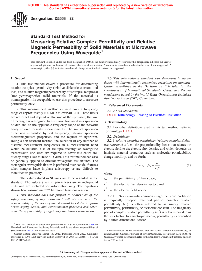


Standards Content (Sample)
NOTICE: This standard has either been superseded and replaced by a new version or withdrawn.
Contact ASTM International (www.astm.org) for the latest information
Designation: D5568 − 22
Standard Test Method for
Measuring Relative Complex Permittivity and Relative
Magnetic Permeability of Solid Materials at Microwave
1
Frequencies Using Waveguide
This standard is issued under the fixed designation D5568; the number immediately following the designation indicates the year of
original adoption or, in the case of revision, the year of last revision. A number in parentheses indicates the year of last reapproval. A
superscript epsilon (´) indicates an editorial change since the last revision or reapproval.
1. Scope* 1.5 This international standard was developed in accor-
dance with internationally recognized principles on standard-
1.1 This test method covers a procedure for determining
ization established in the Decision on Principles for the
relative complex permittivity (relative dielectric constant and
Development of International Standards, Guides and Recom-
loss)andrelativemagneticpermeabilityofisotropic,reciprocal
mendations issued by the World Trade Organization Technical
(non-gyromagnetic) solid materials. If the material is
Barriers to Trade (TBT) Committee.
nonmagnetic, it is acceptable to use this procedure to measure
permittivity only.
2. Referenced Documents
1.2 This measurement method is valid over a frequency
2
2.1 ASTM Standards:
range of approximately 100 MHz to over 40 GHz.These limits
D1711 Terminology Relating to Electrical Insulation
are not exact and depend on the size of the specimen, the size
of rectangular waveguide transmission line used as a specimen
3. Terminology
holder, and on the applicable frequency range of the network
3.1 For other definitions used in this test method, refer to
analyzer used to make measurements. The size of specimen
Terminology D1711.
dimension is limited by test frequency, intrinsic specimen
3.2 Definitions:
electromagnetism properties, and the request of algorithm.
3.2.1 relative complex permittivity (relative complex dielec-
Being a non-resonant method, the selection of any number of
*
tric constant),ε ,n—the proportionality factor that relates the
discrete measurement frequencies in a measurement band
r
electric field to the electric flux density, and which depends on
would be suitable. Use of multiple rectangular waveguide
intrinsic material properties such as molecular polarizability,
transmission line sizes are required to cover this entire fre-
charge mobility, and so forth:
quency range (100 MHz to 40 GHz). This test method can also
be generally applied to circular waveguide test fixtures. The
W
D
* ' ''
rectangular waveguide fixture is preferred over coaxial fixtures
ε 5ε 2 jε 5 (1)
r r r
W
ε E
when samples have in-plane anisotropy or are difficult to 0
manufacture precisely.
where:
1.3 The values stated in SI units are to be regarded as the
ε = the permittivity of free space,
0
standard. The values given in parentheses are in inch-pound →
D = the electric flux density vector, and
units and are included for information only. The equations
→
+jωt
E = the electric field vector.
shown here assume an e harmonic time convention.
1.4 This standard does not purport to address all of the
3.2.1.1 Discussion—In common usage the word “relative”
safety concerns, if any, associated with its use. It is the
is frequently dropped. The real part of complex relative
'
responsibility of the user of this standard to establish appro-
permittivity (ε ) is often referred to as simply relative
r
priate safety, health, and environmental practices and deter-
permittivity, permittivity, or dielectric constant. The imaginary
''
mine the applicability of regulatory limitations prior to use.
part of complex relative permittivity (ε ) is often referred to as
r
the loss factor. In anisotropic media, permittivity is described
by a three dimensional tensor.
1
This test method is under the jurisdiction of ASTM Committee D09 on
Electrical and Electronic Insulating Materials and is the direct responsibility of
2
Subcommittee D09.12 on Electrical Tests. For referenced ASTM standards, visit the ASTM website, www.astm.org, or
Current edition approved March 15, 2022. Published April 2022. Originally contact ASTM Customer Service at service@astm.org. For Annual Book of ASTM
approved in 1994. Last previous edition approved in 2014 as D5568 – 14. DOI: Standards volume information, refer to the standard’s Document Summary page on
10.1520/D5568-22. the ASTM website.
*A Summary of Changes section appears at the end of this standard
Copyright © ASTM International, 100 Barr Harbor Drive, PO Box C700, West Conshohocken, PA 19428-2959. United States
1
---------------------- Page: 1 ----------------------
D5568 − 22
3.2.1.2 Discussion—For the purposes of this test method, 3.3.4 scattering parameter (S-parameter), S ,n—a complex
ij
the media is considered to be isotropic and, therefore, permit- number consis
...
This document is not an ASTM standard and is intended only to provide the user of an ASTM standard an indication of what changes have been made to the previous version. Because
it may not be technically possible to adequately depict all changes accurately, ASTM recommends that users consult prior editions as appropriate. In all cases only the current version
of the standard as published by ASTM is to be considered the official document.
Designation: D5568 − 14 D5568 − 22
Standard Test Method for
Measuring Relative Complex Permittivity and Relative
Magnetic Permeability of Solid Materials at Microwave
1
Frequencies Using Waveguide
This standard is issued under the fixed designation D5568; the number immediately following the designation indicates the year of
original adoption or, in the case of revision, the year of last revision. A number in parentheses indicates the year of last reapproval. A
superscript epsilon (´) indicates an editorial change since the last revision or reapproval.
1. Scope*
1.1 This test method covers a procedure for determining relative complex permittivity (relative dielectric constant and loss) and
relative magnetic permeability of isotropic, reciprocal (non-gyromagnetic) solid materials. If the material is nonmagnetic, it is
acceptable to use this procedure to measure permittivity only.
1.2 This measurement method is valid over a frequency range of approximately 100 MHz to over 40 GHz. These limits are not
exact and depend on the size of the specimen, the size of rectangular waveguide transmission line used as a specimen holder, and
on the applicable frequency range of the network analyzer used to make measurements. The size of specimen dimension is limited
by test frequency, intrinsic specimen electromagnetism properties, and the request of algorithm. Being a non-resonant method, the
selection of any number of discrete measurement frequencies in a measurement band would be suitable. Use of multiple
rectangular waveguide transmission line sizes are required to cover this entire frequency range (100 MHz to 40 GHz). This test
method can also be generally applied to circular waveguide test fixtures. The rectangular waveguide fixture is preferred over
coaxial fixtures when samples have in-plane anisotropy or are difficult to manufacture precisely.
1.3 The values stated in SI units are to be regarded as the standard. The values given in parentheses are in inch-pound units and
+jωt
are included for information only. The equations shown here assume an e harmonic time convention.
1.4 This standard does not purport to address all of the safety concerns, if any, associated with its use. It is the responsibility
of the user of this standard to establish appropriate safety safety, health, and healthenvironmental practices and determine the
applicability of regulatory limitations prior to use.
1.5 This international standard was developed in accordance with internationally recognized principles on standardization
established in the Decision on Principles for the Development of International Standards, Guides and Recommendations issued
by the World Trade Organization Technical Barriers to Trade (TBT) Committee.
2. Referenced Documents
2
2.1 ASTM Standards:
D1711 Terminology Relating to Electrical Insulation
1
This test method is under the jurisdiction of ASTM Committee D09 on Electrical and Electronic Insulating Materials and is the direct responsibility of Subcommittee
D09.12 on Electrical Tests.
Current edition approved Nov. 1, 2014March 15, 2022. Published November 2014April 2022. Originally approved in 1994. Last previous edition approved in 20082014
as D5568 – 08.D5568 – 14. DOI: 10.1520/D5568-14.10.1520/D5568-22.
2
For referenced ASTM standards, visit the ASTM website, www.astm.org, or contact ASTM Customer Service at service@astm.org. For Annual Book of ASTM Standards
volume information, refer to the standard’s Document Summary page on the ASTM website.
*A Summary of Changes section appears at the end of this standard
Copyright © ASTM International, 100 Barr Harbor Drive, PO Box C700, West Conshohocken, PA 19428-2959. United States
1
---------------------- Page: 1 ----------------------
D5568 − 22
3. Terminology
3.1 For other definitions used in this test method, refer to Terminology D1711.
3.2 Definitions:
*
3.2.1 relative complex permittivity (relative complex dielectric constant), ε , n—the proportionality factor that relates the electric
r
field to the electric flux density, and which depends on intrinsic material properties such as molecular polarizability, charge
mobility, and so forth:
W
D
* ' ''
ε 5 ε 2 jε 5 (1)
r r r
W
ε E
0
where:
ε = the permittivity of free space,
0
→
D = the electric flux density vector, and
→
E = the electric field vector.
3.2.1.1 Discussion—
'
In common usage the word “relative” is frequently dropped. The real part of complex relative permittivity (ε ) is often referred
r
''
to as simply relative permittivity, permittivity, or dielectric constant. The imaginary p
...
Questions, Comments and Discussion
Ask us and Technical Secretary will try to provide an answer. You can facilitate discussion about the standard in here.