

EN 18039:2026
(Main)Mountaineering equipment - Autobelay devices for recreational use - Safety requirements and test methods
- Abstract
This document specifies requirements, test methods, marking and information to be supplied for autobelay devices, intended to protect against falls during recreational use in a climbing structure. An autobelay device is a movable personal fall protection system for single person use.
This document does not specify requirements for descender devices or retractable fall arresters that are used for descending/climbing in mountaineering, rescue, rope access, fall arrest or work positioning systems.
NOTE 1 A climbing structure is e.g. a ropes course, a climbing gym.
NOTE 2 An autobelay device which enables the user to belay and descent himself/herself and which conforms to this document is personal protective equipment (PPE).
NOTE 3 For mountaineering standards, see Annex E.
- Status
- Published
- Publication Date
- 18-Aug-2026
- Technical Committee
- CEN/TC 136 - Sports, playground and other recreational equipment
- Drafting Committee
- CEN/TC 136/WG 5 - Mountaineering and climbing equipment
- Current Stage
- 6060 - Definitive text made available (DAV) - Publishing
- Start Date
- 19-Aug-2026
- Due Date
- 27-May-2025
- Completion Date
- 19-Aug-2026

EN 18039:2026 is a CEN standard for autobelay devices used in recreational climbing structures. It specifies safety requirements, test methods, marking, and manufacturer information for single-person devices that automatically manage the safety line and control the user’s descent.
The standard is intended for manufacturers, test laboratories, climbing-wall and ropes-course operators, and buyers or safety managers who need to check whether an autobelay device is suitable for its intended recreational use.
What does EN 18039:2026 specify?
EN 18039:2026 covers autobelay devices intended to protect against falls during recreational use in a climbing structure. It also treats an autobelay device that lets the user belay and descend independently as personal protective equipment (PPE).
EN 18039:2026 does not cover descender devices or retractable fall arresters used for descending or climbing in mountaineering, rescue, rope access, fall arrest, or work positioning systems. In practice, that means the standard is for climbing-structure use, not for general rope-access or rescue equipment.
The document is organised into these main clauses: Scope, Normative references, Terms and definitions, Requirements, Test methods, Marking, and Manufacturer’s instructions and information. It then adds informative annexes that give practical guidance, examples, related standards, and the EU legal relationship.
| Annex | What it covers |
|---|---|
| Annex A | Autobelay Device Belay Gate and how it should help prevent incorrect use |
| Annex B | Example pictograms for the autobelay device climbing start |
| Annex C | Speed climbing immanent risk and related precautions |
| Annex D | Standards on mountaineering equipment |
| Annex ZA | Relationship with the safety requirements of Directive 2001/95/EC |
What are the key requirements of EN 18039:2026?
EN 18039:2026 focuses on safe construction, reliable descent control, predictable performance under load, and clear user information. Clause 4 sets the product requirements, and Clause 5 defines how they are checked.
Design, materials and user connection
Clause 4.1.1 requires the minimum rated load to be stated and the maximum rated load to be at least 100 kg. It also requires the device to avoid sharp edges, rough surfaces, and trapping gaps that could injure the user or damage the retractable safety line.
Clause 4.1.2 and 4.1.3 control the retractable safety line and the connection element. The line may be made from galvanized steel wire rope, stainless-steel wire rope, textile rope, or webbing, but each type has its own construction and termination rules. The connection element must conform to EN 362 or EN 12275, with a secure gate locking arrangement to reduce the risk of accidental opening.
In practice, these requirements matter because the user’s attachment point is the main safety interface. The manufacturer has to choose compatible materials, terminations, and connectors that can be inspected and can survive repeated use.
Classes, extensions, and dynamic performance
Clause 4.1.4 distinguishes class A and class B autobelay devices by safety line extension length. Class A has a safety line extension of 70 cm or less, while class B has more than 70 cm and can support additional functions such as freefall arrangements.
Clauses 4.3.1 to 4.3.4 set the dynamic strength requirements. The device must not release the test mass, must not show tearing or breakage, and the braking force must stay within the stated limit. Landing speed is also limited, with a higher limit allowed when a fall attenuation floor is used.
The practical effect is that the device has to manage a fall or dynamic movement without becoming an uncontrolled drop. For buyers and operators, class B needs extra attention because it covers more demanding use cases.
Retraction, function, and environmental use
Clause 4.2 requires the retraction system to be easy to check and safe if it malfunctions. The device must provide a quick way to verify that retraction works, the retractable safety line must not unravel dangerously if the system fails, and the line must retract fully even after twisting. The retraction speed also has minimum values, and speed climbing devices have a higher minimum.
Clause 4.4 requires the device to work in dry and wet conditions, and in colder conditions if the manufacturer claims those uses. The standard use condition must always be met, and any claimed wet/cold or dry/very cold use must pass the relevant function tests.
This matters because real climbing sites see moisture, temperature changes, and heavy repeated use. The manufacturer has to state the allowed environmental conditions, and the operator has to use the device within them.
Descent energy, static strength, corrosion, and electrical support
Clause 4.5 classifies the descent energy that the device must withstand through repeated descents. The device must still function properly after the specified energy exposure, and the retractable safety line must remain serviceable according to the stated criteria.
Clause 4.6 sets static strength checks for the autobelay device, the blocked device, and the retractable safety line. Clause 4.7 requires corrosion resistance sufficient to avoid functional impairment after salt-spray exposure.
Clause 4.8 applies when the device uses electrical support for safety-relevant functions. In that case, the user must get visible indication of operating status and abnormal energy supply conditions, and the electrical, battery, charger, motor, controller, and EMC aspects must align with the named companion standards.
What terms does EN 18039:2026 define?
- Autobelay device - An automatic device installed above the user that retraction-controls the safety line and lowers the user at a safe speed when loaded.
- Class A autobelay device - A device with a safety line extension of 70 cm or less, intended for climbing up and descending without impact.
- Class B autobelay device - A device with a safety line extension greater than 70 cm, used for additional functions such as freefall.
- Retractable safety line - The self-retractable lanyard of the autobelay device that connects to the user.
- Safety line extension - A permanent or temporary element added to the end of the retractable safety line that does not retract into the device.
- Connection element - The integral connector between the attachment point and the user’s harness attachment point.
- Descent energy - The energy produced by descent load, gravity, descent height, and number of descents, expressed in joules.
- Anchor point - The part of the autobelay device used to connect it to the load-bearing structure.
Who uses EN 18039:2026?
EN 18039:2026 is used by manufacturers designing autobelay devices, by test laboratories carrying out the required examinations, and by certification or compliance teams checking product claims.
It is also used by climbing gyms, ropes-course operators, and safety managers who need to select, install, inspect, maintain, and operate autobelay devices within the manufacturer’s stated limits. Buyers use it to compare devices by class, load range, environmental use, and marking.
Which standards are used with EN 18039:2026?
| Standard | Contribution to EN 18039:2026 |
|---|---|
| EN 362:2004 | Connectors for the user attachment side |
| EN 364:1992 | Test methods and test apparatus for fall protection testing |
| EN 1176-1:2017+A1:2023 | Fall attenuation surfaces for higher fall heights |
| EN 1891:1998 | Low stretch kernmantel rope requirements |
| EN 12275:2013 | Mountaineering connectors, including class T |
| EN 12385-1:2002+A1:2008 | General safety requirements for steel wire ropes |
| EN 13411-1:2002+A1:2008 | Thimbles for wire rope slings |
| EN 13411-2:2001+A1:2008 | Splicing of eyes for wire rope slings |
| EN 13411-3:2022 | Ferrules and ferrule-secured terminations |
| EN 15567-1:2015+A1:2020 | Ropes-course construction and safety requirements |
| EN 60335-1:2012 and parts 2-29, 2-30, 2-80 | Electrical appliance safety for chargers, heaters, and fans used in supported systems |
| EN 60529:1991 | IP enclosure protection for controllers |
| EN 61558-2-16:2009 | Switch-mode power supply and transformer safety |
| EN 62133-1:2017 and EN 62133-2:2017 | Battery safety for nickel and lithium systems |
| EN IEC 55014-1:2021 and EN IEC 55014-2:2021 | EMC emission and immunity for appliance-type equipment |
| EN IEC 61000-6-2:2019 and EN IEC 61000-6-3:2021 | EMC immunity and emission for industrial and residential environments |
| EN IEC 62368-1:2020 | Safety of audio/video, ICT, and similar electronic equipment |
| EN ISO 9227:2022 | Neutral salt-spray corrosion testing |
| EN ISO 13849-1:2023 | Safety-related parts of control systems |
EN 341:2011 is also referenced in the document’s definition and energy discussion for descent-energy context.
What does the EN 18039:2026 document contain?
EN 18039:2026 contains component terminology figures, including the route, anchor point, connection element, retractable safety line, and safety line extension. It also includes detailed test set-ups for retraction system malfunction, twisting, shock load, dyno, freefall performance, and energy-dissipating elements.
The document gives worked test procedures for environmental function testing, descent-energy testing, static strength, and corrosion resistance. These procedures tell laboratories what to load, how to condition the device, and what to measure.
It also includes marking requirements for the device, the retractable safety line termination, and the climbing start, plus extensive manufacturer’s instructions covering use limits, maintenance, rescue planning, attachment, transportation, cleaning, and mis-connection prevention.
Relations
- Effective Date
- 23-Sep-2026
- Effective Date
- 23-Sep-2026
- Refers
EN 13411-3:2022 - Terminations for steel wire ropes - Safety - Part 3: Ferrules and ferrule-securing - Effective Date
- 23-Sep-2026
- Refers
EN ISO 9227:2022 - Corrosion tests in artificial atmospheres - Salt spray tests (ISO 9227:2022) - Effective Date
- 23-Sep-2026
- Effective Date
- 23-Sep-2026
- Effective Date
- 23-Sep-2026
- Effective Date
- 23-Sep-2026
- Effective Date
- 02-Sep-2026
Get Certified
Connect with accredited certification bodies for this standard

CIS Institut d.o.o.
Personal Protective Equipment (PPE) certification body. Notified Body NB-2890 for EU Regulation 2016/425 PPE.

Kiwa BDA Testing
Building and construction product certification.
Kmetijski inštitut Slovenije
Agricultural Institute of Slovenia. Soil testing, plant health, agricultural product analysis.
Sponsored listings
Frequently Asked Questions
EN 18039:2026 is a standard published by the European Committee for Standardization (CEN). Its full title is "Mountaineering equipment - Autobelay devices for recreational use - Safety requirements and test methods". This standard covers: This document specifies requirements, test methods, marking and information to be supplied for autobelay devices, intended to protect against falls during recreational use in a climbing structure. An autobelay device is a movable personal fall protection system for single person use. This document does not specify requirements for descender devices or retractable fall arresters that are used for descending/climbing in mountaineering, rescue, rope access, fall arrest or work positioning systems. NOTE 1 A climbing structure is e.g. a ropes course, a climbing gym. NOTE 2 An autobelay device which enables the user to belay and descent himself/herself and which conforms to this document is personal protective equipment (PPE). NOTE 3 For mountaineering standards, see Annex E.
This document specifies requirements, test methods, marking and information to be supplied for autobelay devices, intended to protect against falls during recreational use in a climbing structure. An autobelay device is a movable personal fall protection system for single person use. This document does not specify requirements for descender devices or retractable fall arresters that are used for descending/climbing in mountaineering, rescue, rope access, fall arrest or work positioning systems. NOTE 1 A climbing structure is e.g. a ropes course, a climbing gym. NOTE 2 An autobelay device which enables the user to belay and descent himself/herself and which conforms to this document is personal protective equipment (PPE). NOTE 3 For mountaineering standards, see Annex E.
EN 18039:2026 is classified under the following ICS (International Classification for Standards) categories: 13.340.60 - Protection against falling and slipping; 97.220.40 - Outdoor and water sports equipment. The ICS classification helps identify the subject area and facilitates finding related standards.
EN 18039:2026 has the following relationships with other standards: It is inter standard links to EN 15567-1:2015+A1:2020, EN 13411-2:2001+A1:2008, EN 13411-3:2022, EN ISO 9227:2022, EN 12385-1:2002+A1:2008, EN 1176-1:2017+A1:2023, EN 13411-1:2002+A1:2008, EN 341:2011. Understanding these relationships helps ensure you are using the most current and applicable version of the standard.
EN 18039:2026 is associated with the following European legislation: EU Directives/Regulations: 2016/425; Standardization Mandates: M/571, M/571 Amd 1. When a standard is cited in the Official Journal of the European Union, products manufactured in conformity with it benefit from a presumption of conformity with the essential requirements of the corresponding EU directive or regulation.
EN 18039:2026 is available in PDF format for immediate download after purchase. The document can be added to your cart and obtained through the secure checkout process. Digital delivery ensures instant access to the complete standard document.
Standards Content (Sample)
SLOVENSKI STANDARD
01-december-2026
Gorniška oprema - Samovarovala za rekreativno uporabo - Varnostne zahteve in
preskusne metode
Mountaineering equipment - Autobelay devices for recreational use - Safety
requirements and test methods
Persönliche Absturzschutzausrüstung - Selbstsicherungs-Automaten im
Freizeitsportbereich - Sicherheitsanforderungen und Prüfverfahren
Equipement d'alpinisme et d'escalade - Auto-assureur automatique pour le loisir
Ta slovenski standard je istoveten z: EN 18039:2026
ICS:
13.340.60 Zaščita pred padci in zdrsi Protection against falling and
slipping
97.220.40 Oprema za športe na Outdoor and water sports
prostem in vodne športe equipment
2003-01.Slovenski inštitut za standardizacijo. Razmnoževanje celote ali delov tega standarda ni dovoljeno.
EN 18039
EUROPEAN STANDARD
NORME EUROPÉENNE
August 2026
EUROPÄISCHE NORM
ICS 13.340.60
English Version
Mountaineering equipment - Autobelay devices for
recreational use - Safety requirements and test methods
Équipement d'alpinisme et d'escalade - Auto-assureurs Bergsteigerausrüstung - Selbstsicherungs-Automaten
automatiques pour le loisir - Exigences de sécurité et im Freizeitsportbereich - Sicherheitsanforderungen
méthodes d'essai und Prüfverfahren
This European Standard was approved by CEN on 29 June 2026.
CEN members are bound to comply with the CEN/CENELEC Internal Regulations which stipulate the conditions for giving this
European Standard the status of a national standard without any alteration. Up-to-date lists and bibliographical references
concerning such national standards may be obtained on application to the CEN-CENELEC Management Centre or to any CEN
member.
This European Standard exists in three official versions (English, French, German). A version in any other language made by
translation under the responsibility of a CEN member into its own language and notified to the CEN-CENELEC Management
Centre has the same status as the official versions.
CEN members are the national standards bodies of Austria, Belgium, Bulgaria, Croatia, Cyprus, Czech Republic, Denmark, Estonia,
Finland, France, Germany, Greece, Hungary, Iceland, Ireland, Italy, Latvia, Lithuania, Luxembourg, Malta, Netherlands, Norway,
Poland, Portugal, Republic of North Macedonia, Romania, Serbia, Slovakia, Slovenia, Spain, Sweden, Switzerland, Türkiye and
United Kingdom.
EUROPEAN COMMITTEE FOR STANDARDIZATION
COMITÉ EUROPÉEN DE NORMALISATION
EUROPÄISCHES KOMITEE FÜR NORMUNG
CEN-CENELEC Management Centre: Rue de la Science 23, B-1040 Brussels
© 2026 CEN All rights of exploitation in any form and by any means reserved Ref. No. EN 18039:2026 E
worldwide for CEN national Members.
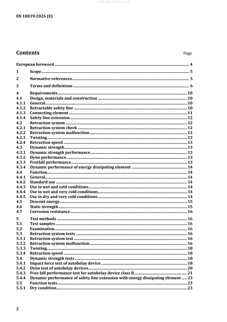
Contents Page
European foreword . 4
1 Scope . 5
2 Normative references . 5
3 Terms and definitions . 6
4 Requirements . 10
4.1 Design, materials and construction . 10
4.1.1 General. 10
4.1.2 Retractable safety line . 10
4.1.3 Connecting element . 11
4.1.4 Safety line extension . 12
4.2 Retraction system . 12
4.2.1 Retraction system check . 12
4.2.2 Retraction system malfunction . 12
4.2.3 Twisting . 12
4.2.4 Retraction speed . 13
4.3 Dynamic strength . 13
4.3.1 Dynamic strength performance . 13
4.3.2 Dyno performance . 13
4.3.3 Freefall performance . 13
4.3.4 Dynamic performance of energy dissipating element . 14
4.4 Function . 14
4.4.1 General. 14
4.4.2 Standard use . 14
4.4.3 Use in wet and cold conditions . 14
4.4.4 Use in wet and very cold conditions . 14
4.4.5 Use in dry and very cold conditions . 14
4.5 Descent energy. 15
4.6 Static strength . 15
4.7 Corrosion resistance . 16
5 Test methods . 16
5.1 Test samples . 16
5.2 Examination . 16
5.3 Retraction system tests . 16
5.3.1 Retraction system test . 16
5.3.2 Retraction system malfunction . 16
5.3.3 Twisting . 18
5.3.4 Retraction speed . 18
5.4 Dynamic strength tests . 18
5.4.1 Impact force test of autobelay device . 18
5.4.2 Dyno test of autobelay devices . 20
5.4.3 Free fall performance test for autobelay device class B . 21
5.4.4 Dynamic performance of safety line extension with energy dissipating element . 23
5.5 Function tests . 23
5.5.1 Dry condition . 23
5.5.2 Wet condition . 23
5.5.3 Wet and cold condition . 23
5.5.4 Wet and very cold condition . 23
5.5.5 Dry and very cold condition . 24
5.5.6 Function test method . 24
5.6 Descent energy test . 24
5.7 Static strength test . 26
5.7.1 General . 26
5.7.2 Static strength test of the retractable safety line end in the autobelay device . 26
5.7.3 Static strength test of the autobelay device . 26
5.7.4 Static strength of the retractable safety line. 27
5.8 Corrosion resistance test . 27
6 Marking . 27
6.1 General . 27
6.2 On the device . 27
6.3 On a termination of the retractable safety line. 28
6.4 On the climb start . 28
7 Manufacturer’s instructions and information . 28
Annex A (informative) Autobelay device belay gate . 31
Annex B (informative) Examples for pictograms at autobelay device climbing start . 32
Annex C (informative) Speed climbing immanent risk . 33
Annex D (informative) Electrical supported systems . 34
Annex E (informative) Standards on mountaineering equipment . 35
Annex ZA (informative) Relationship between this European Standard and the essential
requirements of Regulation (EU) 2016/425 aimed to be covered . 37
Bibliography . 40
European foreword
This document (EN 18039:2026) has been prepared by Technical Committee CEN/TC 136 “Sports,
playground and other recreational facilities and equipment”, the secretariat of which is held by DIN.
This European Standard shall be given the status of a national standard, either by publication of an
identical text or by endorsement, at the latest by February 2027, and conflicting national standards shall
be withdrawn at the latest by February 2027.
Attention is drawn to the possibility that some of the elements of this document may be the subject of
patent rights. CEN shall not be held responsible for identifying any or all such patent rights.
This document has been prepared under a standardization request addressed to CEN by the European
Commission. The Standing Committee of the EFTA States subsequently approves these requests for its
Member States.
For the relationship with EU Legislation, see informative Annex ZA, which is an integral part of this
document.
Any feedback and questions on this document should be directed to the users’ national standards body.
A complete listing of these bodies can be found on the CEN website.
According to the CEN-CENELEC Internal Regulations, the national standards organisations of the
following countries are bound to implement this European Standard: Austria, Belgium, Bulgaria, Croatia,
Cyprus, Czech Republic, Denmark, Estonia, Finland, France, Germany, Greece, Hungary, Iceland, Ireland,
Italy, Latvia, Lithuania, Luxembourg, Malta, Netherlands, Norway, Poland, Portugal, Republic of North
Macedonia, Romania, Serbia, Slovakia, Slovenia, Spain, Sweden, Switzerland, Türkiye and the United
Kingdom.
1 Scope
This document specifies requirements, test methods, marking and information to be supplied for
autobelay devices, intended to protect against falls during recreational use in a climbing structure. An
autobelay device is a movable personal fall protection system for single person use.
This document does not specify requirements for descender devices or retractable fall arresters that are
used for descending/climbing in mountaineering, rescue, rope access, fall arrest or work positioning
systems.
NOTE 1 A climbing structure is e.g. a ropes course, a climbing gym.
NOTE 2 An autobelay device which enables the user to belay and descent himself/herself and which conforms
to this document is personal protective equipment (PPE).
NOTE 3 For mountaineering standards, see Annex E.
2 Normative references
The following documents are referred to in the text in such a way that some or all of their content
constitutes requirements of this document. For dated references, only the edition cited applies. For
undated references, the latest edition of the referenced document (including any amendments) applies.
EN 341:2011, Personal fall protection equipment — Descender devices for rescue
EN 364:1992, Personal protective equipment against falls from a height — Test methods
EN 1176-1:2017+A1:2023, Playground equipment and surfacing — Part 1: General safety requirements
and test methods
EN 12385-1:2002+A1:2008, Steel wire ropes — Safety — Part 1: General requirements
EN 13411-1:2002+A1:2008, Terminations for steel wire ropes — Safety — Part 1: Thimbles for steel wire
rope slings
EN 13411-2:2001+A1:2008, Terminations for steel wire ropes — Safety — Part 2: Splicing of eyes for wire
rope slings
EN 13411-3:2022, Terminations for steel wire ropes — Safety — Part 3: Ferrules and ferrule-securing
EN 15567-1:2015+A1:2020, Sports and recreational facilities — Ropes courses — Part 1: Construction and
safety requirements
EN ISO 9227:2022, Corrosion tests in artificial atmospheres — Salt spray tests (ISO 9227:2022)
3 Terms and definitions
For the purposes of this document, the following terms and definitions apply.
ISO and IEC maintain terminology databases for use in standardization at the following addresses:
— ISO Online browsing platform: available at https://www.iso.org/obp
— IEC Electropedia: available at https://www.electropedia.org/
3.1
autobelay device
automatically operated device, usually installed on top of a route and above the user, including a
retractable safety line, to which the user is connected, that allows climbing up without slack in the
retractable safety line and, in case of loading the retractable safety line by the user, lowers the user
automatically speed-regulated at a safe speed
Note 1 to entry: The device has a braking system that does not require an intervention for speed regulation by the
user once the descent has commenced.
Note 2 to entry: The use of an additional redundant stop braking system is also possible and acceptable, provide
that the additional redundant stop brake does not interfere during normal use.
3.1.1
class A autobelay device
autobelay device which has a safety line extension less than or equal to 70 cm, intended only for climbing
up and descending without impact
3.1.2
class B autobelay device
autobelay device which has a safety line extension greater than 70 cm, for additional functions
EXAMPLE Freefall devices with a slack in retractable safety line.
3.1.3
autobelay device for speed climbing
autobelay device which is intended for climbing style, where high climbing speed is the target
3.2
route
distance between ground floor and height of fully retracted connecting element when autobelay device
is installed in accordance with the product instructions and information
Note 1 to entry: See Figure 1.
Key
1 autobelay device
2 connecting element
3 route
4 climbing hold
Figure 1 — Route
3.3
retractable safety line
self-retractable lanyard of the autobelay device with an attachment point on its outer end termination
Note 1 to entry: See Figure 2.
EXAMPLES Wire rope, textile rope, or webbing.
3.4
safety line extension
element permanently or temporarily added to the end of retractable safety line (3.3) that does not retract
into the belay device and provides a new fixation for the connecting element and also additional functions
Note 1 to entry: Examples of additional functions are but not limited to elastic webbing assemblies for freefall, or
energy absorbers or line extensions required for specific site applications.
3.5
connecting element
integral element permitting connection between the attachment point and the harness attachment point
Note 1 to entry: See Figure 2.
3.6
attachment point
component of the retractable safety line permitting the fixation of the connecting element or temporary
safety line extension
Note 1 to entry: See Figure 2.
3.7
anchor point
component of the autobelay device which is used to connect the autobelay device to the load bearing
structure
Note 1 to entry: See Figure 2.
Key
1 anchor point
2 connecting element
3 retractable safety line
4 attachment point
Figure 2 — Terminology of autobelay device components
3.8
descent energy
energy measured in joules and expressed as W, which results from the product of the descent load, the
gravity, the descent height and the number of descents
Note 1 to entry:
Descent energy W = m × g × h × n
where
W is the descent energy, expressed in joules (J);
m is the descent mass, expressed in kilograms (kg);
g is the gravity 9,81 m/s ;
h is the descent height, expressed in metres (m);
n is the number of descents.
[SOURCE: EN 341:2011, 3.1.2]
3.9
minimum rated load
minimum mass of the user, including all gear, as specified in the product instructions and information
Note 1 to entry: Minimum rated load is expressed in kilograms.
3.10
maximum rated load
maximum mass of the user, including all gear, as specified in the product instructions and information
Note 1 to entry: Maximum rated load is expressed in kilograms.
3.11
energy dissipating element
element or component or arrangement of a fall arresting system, which is designed to reduce impact force
of the kinetic energy developed during a fall of the user
3.12
braking force
maximum force F in kilonewtons measured at the anchor point during the braking period of the
max
dynamic strength test
3.13
minimum mounting height
shortest vertical distance between ground and anchor point of autobelay device which is allowed in the
product instructions and information
3.14
maximum mounting height
longest vertical distance between ground and anchor point of autobelay device which is allowed in the
product instructions and information
3.15
man-made fibre
fibre obtained by a manufacturing process
Note 1 to entry: For more information on man-made fibre, refer to ISO/TR 11827:2012.
3.16
twin-safety line
two independent retractable safety lines permanently connected together
4 Requirements
4.1 Design, materials and construction
4.1.1 General
The minimum rated load shall be specified according to 6.2 h).
The maximum rated load shall be specified in the product instructions and information and shall be at
least 100 kg according to 6.2 h).
The materials which may come into contact with the skin of a user shall not be known to, or suspected to,
adversely affect user hygiene or health, e.g. cause irritating or sensitization effects, during normal use of
the autobelay device, according to 5.2.
The autobelay devices shall not have sharp or rough edges that may cut, abrade or otherwise damage
retractable safety line or cause injury to the user, according to 5.2.
There shall be no gaps between 8 mm and 25 mm and with a depth greater than 15 mm which can lead
to entrapment according to 5.2. Finger entrapment does not apply to anchor points and connecting
element.
The energy dissipating elements of the autobelay device shall transmit an impact force not exceeding
6 kN, when tested according to 5.4.
NOTE For electrical supported systems, see informative Annex D.
4.1.2 Retractable safety line
4.1.2.1 General
The retractable safety line shall be made of galvanized steel wire rope or stainless-steel wire rope, textile
rope or webbing.
The retractable safety line shall have a connecting element intended for attachment of a user.
The retractable safety line including its terminations shall allow inspections as specified in the product
instructions and information. All requirements of this subclause are to be checked according to 5.2.
NOTE It is advisable to take care that the retractable safety line has an adequate protection against abrasive
climbing wall surfaces.
4.1.2.2 Attachment point
The attachment point shall be terminated using appropriate methods depending on the retractable safety
line material(s). The structural material of the attachment point shall be protected from wear.
All requirements of this subclause are checked in 5.2.
4.1.2.3 Wire rope retractable safety line
The wire rope retractable safety line shall be made in one piece and shall be stress and torsion relieved.
The wire rope retractable safety line made of steel, except stainless steel, shall be galvanized in
accordance with EN 12385-1:2002+A1:2008.
The nominal tensile strength of the metallic wire rope of the retractable safety line shall be less or equal
to 1 960 N/mm .
All requirements of this subclause are to be checked according to 5.2.
NOTE 1 For autobelay devices, it is advisable to be particularly careful when selecting lines made of stainless
steel as some types of stainless steel can have unpredictable fatigue and corrosion characteristics.
NOTE 2 A limit of the nominal tensile strength is necessary, because the wires become too brittle with a higher
nominal tensile strength.
4.1.2.4 Textile rope retractable safety line
The textile rope retractable safety line shall be of kernmantel construction and shall be suitable for its
intended purpose, e.g. in accordance with EN 1891:1998, 4.5, type A. They shall be made of man-made
fibres suitable for the use intended.
All requirements of this subclause are checked in 5.2.
4.1.2.5 Webbing retractable safety line
The webbing retractable safety line shall meet the requirements suitable for its intended purpose, e.g. in
accordance EN 1891:1998, 4.5, type A.
The webbing retractable safety line shall be made of man-made fibres suitable for the use intended.
All requirements of this subclause are checked in 5.2.
4.1.2.6 Termination
The retractable safety line shall be terminated on the user side in such a manner that it can be connected,
directly or by a connecting element, as specified in the product instructions and information, to the
harness of the user.
Reinforcement or other methods shall be used to reduce abrasion of connecting element due to
concentrated wear at all retractable safety line-to-metal fitting interfaces.
Where visible stitching is used to provide safety and strength (e.g. in joints) it shall contrast with the
webbing/rope in colour or surface appearance.
Webbing/textile rope ends shall be sealed or otherwise prevented from unravelling.
All splices shall be secured to prevent splice moving.
The eye terminations of wire rope shall be made with thimbles and splices or with thimbles and pressed
ferrules, in accordance with EN 13411-1:2002+A1:2008, EN 13411-2:2001+A1:2008 and
EN 13411-3:2022.
All requirements of this subclause are to be checked according to 5.2.
4.1.3 Connecting element
The connecting element shall be suitable for its intended purpose, e.g. in accordance with EN 362:2004,
class M or T, or EN 12275:2013, class T, with triple action gate locking device or comparable safe gate
locking device (e.g. 2 opposing double action gates, gate locked with key) to prevent accidental opening
during use.
The reinforcement or other methods shall be used to reduce abrasion of connecting element due to
concentrated wear at all retractable safety line-to-metal fitting interfaces.
All requirements of this subclause are to be checked according to 5.2. It is recommended to take care that
the connecting element has an adequate protection against abrasive climbing wall surfaces.
4.1.4 Safety line extension
The safety line extension shall be made of galvanized steel wire rope or stainless-steel wire rope, textile
rope or webbing.
The safety line extension shall have a connecting element intended for attachment of a user.
The safety line extension including its terminations shall allow inspections as specified in the product
instructions and information.
All terminations of the safety line extension structural material shall be protected from wear.
The safety line extensions shall have a permanent or openable connection to the retractable safety line.
The openable safety line extension connection to the retractable safety line shall be openable only with a
tool.
All above requirements of this subclause are to be checked according to 5.2.
The safety line extension shall be assessed in combination with the autobelay device in 4.3, 4.5, 4.6.
The autobelay device class A shall have a safety line extension ≤ 70 cm. The safety line extension for
class A that is part of an energy absorbing system shall have an impact force ≤ 6 kN when tested in
accordance with 5.4.1.
The autobelay device class B shall have a safety line extension > 70 cm.
The safety line extension for class B that is part of an energy absorbing system shall have an impact
force ≤ 6 kN when tested in accordance with 5.4.1 and 5.4.3.
The safety line extension with energy dissipating element for safety purposes shall have an impact
force ≤ 6 kN when tested in accordance with 5.4.4.
4.2 Retraction system
4.2.1 Retraction system check
An autobelay device shall have an indicator or control procedure which allows evaluating in short time
the function of retracting retractable safety line. This shall be prescribed in the product instructions and
information. When tested in accordance with 5.3.1 the performing of evaluation shall not need more than
10 seconds.
4.2.2 Retraction system malfunction
An autobelay device shall be constructed in such a way that there is no safety problem when, during a
climb, the retraction system for the retractable safety line has a malfunction and the user stops climbing
up. When tested in accordance with 5.3.2, the retractable safety line shall not unravel itself and a mass
equivalent to the maximum rated load shall descent at a safe landing speed (see 4.4.2).
4.2.3 Twisting
When tested in accordance with 5.3.3, the retractable safety line shall be retracted fully into the autobelay
device.
This test is not required for twin-safety lines.
4.2.4 Retraction speed
When tested in accordance with 5.3.4, an autobelay device shall have a retraction speed > 0,5 m/s.
When tested in accordance with 5.3.4, an autobelay device for speed climbing shall have a retraction
speed > 3,5 m/s.
4.3 Dynamic strength
4.3.1 Dynamic strength performance
This requirement applies for autobelay device classes A and B.
When tested in accordance with 5.4.1, which simulates a fall on a slack safety line:
— the autobelay device shall not release the test mass;
— no part of the autobelay device shall show sign of breaking or tearing;
— braking force shall be ≤ 6 kN;
— landing speed shall be ≤ 2 m/s;
— or, with fall protection floor, see 4.4.2, landing speed shall be ≤ 3 m/s.
4.3.2 Dyno performance
This requirement applies for autobelay device classes A and B.
When tested in accordance with 5.4.2, which simulates a dynamic move of a climber ending in a fall:
— the autobelay device shall not release the test mass;
— no part of the autobelay device shall show any signs of breaking or tearing;
— the braking force shall be ≤ 6 kN;
— the landing speed shall be ≤ 2 m/s;
— or, with fall protection floor, see 4.4.2, the landing speed shall be ≤ 3 m/s.
4.3.3 Freefall performance
This requirement applies for autobelay device class B.
When tested in accordance with 5.4.3, which simulates a jump from a platform:
— the autobelay device shall not release the test mass;
— no part of the autobelay device shall show any signs of breaking or tearing;
— the braking force shall be ≤ 6 kN;
— the landing speed shall be ≤ 2 m/s;
— or, with fall attenuation surface, see 4.4.2, the landing speed shall be ≤ 3 m/s.
4.3.4 Dynamic performance of energy dissipating element
This requirement applies for autobelay device with energy dissipating element in safety line extension.
When tested in accordance with 5.4.4, which verifies the performance of energy dissipating elements:
— the safety line extension shall not release the test mass;
— the braking force shall be ≤ 6 kN.
4.4 Function
4.4.1 General
The authorized environmental conditions for the use of the autobelay device shall be indicated. Standard
use (see 4.4.2) shall always be met, whilst subclauses 4.4.3 to 4.4.5 shall be met if claimed by the product
instructions and information; see Table 1.
4.4.2 Standard use
When tested in the dry and wet condition in accordance with 5.5.1 and 5.5.2:
— the landing speed shall be maintained between 0,1 m/s and 2 m/s when no specific fall attenuation
surface is required;
— if fall attenuation surface for fall heights > 2 000 mm is used according to EN 1176-1:2017+A1:2023,
the landing speed shall be maintained between 0,1 m/s and 3 m/s.
4.4.3 Use in wet and cold conditions
When claimed in the product instructions and information that the autobelay device can be used in wet
and cold condition according to 5.5.3:
— the landing speed shall be maintained between 0,1 m/s and 2 m/s when no specific fall attenuation
surface is required;
— if fall attenuation surface for fall heights > 2 000 mm is used according to EN 1176-1:2017+A1:2023,
the landing speed shall be maintained between 0,1 m/s and 3 m/s.
4.4.4 Use in wet and very cold conditions
When claimed in the product instructions and information that the autobelay device can be used in wet
and very cold condition in accordance with 5.5.4:
— the landing speed shall be maintained between 0,1 m/s and 2 m/s when no specific fall attenuation
surface is required;
— if fall attenuation surface for fall heights > 2 000 mm is used according to EN 1176-1:2017+A1:2023,
the landing speed shall be maintained between 0,1 m/s and 3 m/s.
4.4.5 Use in dry and very cold conditions
When claimed in the product instructions and information that the autobelay device can be used outdoor
in dry condition (e.g. protected by rain cover, without condensing effects) it shall be tested additionally
in dry and very cold condition in accordance with 5.5.5:
— the landing speed shall be maintained between 0,1 m/s and 2 m/s when no specific fall attenuation
surface is required;
— if fall attenuation surface for fall heights > 2 000 mm is used in accordance with
EN 1176-1:2017+A1:2023, the landing speed shall be maintained between 0,1 m/s and 3 m/s.
Table 1 — Function tests of autobelay devices
Environmental
Mandatory Optional Test subclause
condition
Dry x 5.5.1
Wet x 5.5.2
Wet and cold x 5.5.3
Wet and very cold x 5.5.4
Dry and very cold x 5.5.5
4.5 Descent energy
Autobelay devices are classified as follows:
descent energy W: ≥ 7,5 × 10 J; (10 × class A of EN 341:2011)
NOTE 1 Value is no life time limit but qualification as autobelay device.
NOTE 2 In practice, autobelay devices are subject to different load scenarios which can have different influences
on the life time of the product. This is something to consider with regard to the use, service, maintenance and
disposal of the product.
When tested in accordance with 5.6, with the descents being carried out in succession, the autobelay
device shall meet the following requirements:
a) it shall resist the descent energy W: ≥ 7,5 × 10 J and still has to function properly;
b) it shall be possible to maintain the descent velocity (at landing) between 0,1 m/s and 2 m/s. When
no specific ground floor is required;
c) if appropriate fall attenuation surface for fall heights > 2 m is used (EN 1176-1:2017+A1:2023)
landing speed can be higher up to 3 m/s.
The retractable safety line can be replaced according to the product instructions and information when
it is worn during this testing, but shall meet at least the descent energy W: 1 × 7,5 × 10 J (like
EN 341:2011, class A) and static strength test in 4.6.
After the descent energy test, the textile retractable safety line shall not show any heat damage (melted
fibres); glassy surface is allowed.
After the descent energy test, the steel cable retractable safety line shall not show any wire/cable damage.
4.6 Static strength
When tested in accordance with 5.7.2, autobelay devices shall withstand a test force of 5 times the
+0,25
maximum rated load, but at least 6 kN, applied for min.
When tested in accordance with 5.7.3, autobelay devices with blocked retractable safety line shall hold a
+0,25
test force of 10 times the maximum rated load, but at least 12 kN, applied for 3 min.
When tested in accordance with 5.7.4, the autobelay device retractable safety lines shall withstand a test
+0,25
force of 10 times the maximum rated load, but at least 15 kN, applied for min.
4.7 Corrosion resistance
After testing in accordance with 5.8, no part of the autobelay device shall show evidence of corrosion that
would affect its function.
White scaling or tarnishing is acceptable if the function is not impaired.
NOTE Conformity with this requirement does not imply suitability for use in e.g. a marine environment or
indoor swimming pool.
5 Test methods
5.1 Test samples
A minimum of two new autobelay device samples shall be provided: one for the purposes of the tests
specified in 5.2, 5.3, 5.5 and 5.8 and one for the purposes of the tests specified in 5.4, 5.6 and 5.7.
NOTE Depending on the configuration, the claim in the product instructions and information for the intended
use, the material of the retractable safety line and the class of the device, more than two samples or additional
samples of components can be required.
5.2 Examination
Confirm by reference to appropriate documentation accompanying the autobelay device and by
measurement and by normal or corrected vision and/or tactile examination of the autobelay device that
it conforms to the relevant part of 4.1.1, 4.1.2, 4.1.2.2, 4.1.2.3, 4.1.2.4, 4.1.2.5, 4.1.2.6, 4.1.3 and relevant
part of 4.1.4. If necessary to examine internal parts, dismantle the autobelay device.
5.3 Retraction system tests
5.3.1 Retraction system test
Check the retraction system ability using the method described in the product instructions and
information. Measure and record the time for evaluation.
5.3.2 Retraction system malfunction
The autobelay device retraction system for the retractable safety line is manipulated in accordance with
the product instructions and information in a way that simulates neutralization of a retraction spring
(other failures shall be evaluated if no spring system used).
The manipulated autobelay device is attached by its anchor point to the test apparatus, in accordance
with the product instructions and information, at maximum mounting height (±100) mm. Suspend with
an anchor point within 300 mm maximum horizontal distance from the anchor point used for the
autobelay device a test mass equivalent to the maximum rated load in accordance with manufacturer’s
+100
instructions and information, at a height mm from the ground (see Figure 3).
3 000
Attach the connecting element to a test mass equivalent to the maximum rated load, and then verify if the
retractable safety line comes out of the device without additional pull (only the retractable safety line
weight pulls on it).
+100
Afterwards, raise the test mass with the same test apparatus by mm. Hold the test mass by the
quick release device. Release the test mass without initial velocity (see Figure 3). Record the landing
speed. Verify that the requirements in 4.2.2 are met.
Alternatively, the retractable safety line may be shortened by a knot if testing height is not sufficient.
Dimensions in millimetres
Key
1 test apparatus fixation points
2 autobelay device
3 quick release device
4 retractable safety line
5 test mass with maximum rated load
MH maximum mounting height
max
Figure 3 — Retraction system malfunction test setup
5.3.3 Twisting
The autobelay device is attached by its anchor point to the anchor point of a crane or winch and not
allowed to rotate, in accordance with the product instructions and information, at maximum mounting
height. The retractable safety line, pulled out of the device at its maximum, is twisted with 10 turns in one
direction. While holding the connecting element stationary at its intended user load bearing point, the
autobelay device should be lowered down completely via crane or winch from maximum height to the
connecting element, allowing the retractable safety line to retract, with a retraction speed of minimum
0,5 m/s , but not faster than retraction speed of tested autobelay device.
The retractable safety line shall retract fully and continuously into autobelay device during the lowering
of the autobelay device. All 10 twisted turns in the retractable safety line shall then be untwisted. The test
shall be repeated twisting the retractable safety line 10 turns in the opposite direction.
5.3.4 Retraction speed
Fully extract the vertically free hanging retractable safety line with connecting element from an autobelay
device. Release and calculate average retraction speed for fully retracted retractable safety line with an
uncertainty of measurement of (±0,2) m/s.
The autobelay device can be damaged by letting out the retractable safety line without load on it. If that
occurs in that test, use another test sample for further tests.
The retraction speed increasing or decreasing slightly over the retraction distance is acceptable.
5.4 Dynamic strength tests
5.4.1 Impact force test of autobelay device
The test apparatus shall conform to 4.4.1, 4.4.2 and 4.6 of EN 364:1992. The test masses shall have the
same diameter than those according to EN 364:1992, 4.5.
Attach a new autobelay device by its anchor point to the anchor point of the test apparatus, in accordance
with the product instructions and information, in minimum mounting height. Attach a load cell between
the autobelay device anchor point and the anchor point of the test apparatus. Raise the test mass of
maximum rated load, which is fixed on the connecting element of the retractable safety line
+100
mm off the ground.
3 000
Then prevent the retractable safety line from further retracting by a clamp and raise the test mass by
+50
mm, with a maximum horizontal distance of 300 mm from the anchor point, see Figure 4.
Hold the test mass by the quick release device. Release the test mass without initial velocity.
Measure and record the braking force and the descent speed measured at (1 000 ± 50) mm above the
ground.
Check that the autobelay device does not release the test mass and does not show any signs of breaking
or tearing.
Dimensions in millimetres
Key
1 anchor point
2 quick release device
3 retractable safety line
4 autobelay device
5 test mass (maximum rated load)
6 clamp
7 load cell
MHmin minimum mounting height
Figure 4 — Impact force test for autobelay devices
5.4.2 Dyno test of autobelay devices
The test apparatus shall conform to 4.4.1, 4.4.2 and 4.6 of EN 364:1992. Test masses shall have the same
diameter than those in accordance with EN 364:1992, 4.5.
Attach a new autobelay device by its anchor point to the anchor point of the test apparatus, in accordance
with the product instructions and information, in minimum mounting height. Attach a load cell between
the autobelay device anchor point and the anchor point of the t
...