

prEN 81-21
(Main)Safety rules for the construction and installation of lifts - Lifts for the transport of persons and goods - Part 21: New passenger and goods passenger lifts in existing building
- Abstract
This document specifies the safety rules related to passenger and goods/passenger lifts installed in existing buildings where limitations enforced by certain building constraints mean that some requirements of EN 81-20:2020 cannot be met.
It addresses the following constraints and gives requirements for alternative solutions:
- existing perforate walls of the lift well;
- reduction in available well are leading to reduced distance between car, counterweight or balancing weight;
- counterweight or balancing weight in a separate existing well;
- reduced building dimensions and clearances leading to:
- reductions in available space for headroom and pit;
- reduced car roof balustrade dimensions;
- reduced height of sill apron;
- reduced height of machine and/or pulley room;
- reduced available area for access door/trap door;
- reduction in available height of landing doors.
This document is not applicable to lifts installed before the date of its publication.
- Status
- Not Published
- Publication Date
- 24-Apr-2028
- Technical Committee
- CEN/TC 10 - Passenger, goods and service lifts
- Drafting Committee
- CEN/TC 10/WG 1 - Lifts and service lifts
- Current Stage
- 4010 - Start of draft translation - Enquiry
- Start Date
- 30-Sep-2026
- Completion Date
- 24-Sep-2026


prEN 81-21 is a CEN draft European Standard for new passenger lifts and goods passenger lifts in existing buildings or existing wells. It sets safety rules and alternative technical solutions for installations where some EN ISO 8100-1:2026 requirements cannot be met because of building constraints. It is written for lift manufacturers, installers, designers, maintenance providers, inspectors and the safety bodies that assess these lifts.
What does prEN 81-21 specify?
prEN 81-21 specifies the safety rules for passenger and goods/passenger lifts installed in existing buildings or existing wells when site limitations prevent full use of EN ISO 8100-1:2026. The document focuses on alternative solutions for reduced spaces, openings and clearances, and on how those alternatives are monitored and verified.
The scope covers these constraint types in practice:
- perforate lift-well walls
- reduced distance between car, counterweight or balancing weight
- reduced headroom and pit space
- reduced car roof balustrade dimensions
- reduced sill apron height
- reduced machine-room and pulley-room height
- reduced access-door or trap-door area
- reduced landing-door height
The document applies to lifts in existing buildings, meaning buildings already in use before the lift is installed. It also states that it is not applicable to lifts installed before the date of its publication. The structure of the document runs from Scope, Normative references and Terms through safety requirements, verification, and information for use, with normative Annex A and Annex B and informative Annex ZA.
What are the key requirements of prEN 81-21?
prEN 81-21 replaces full EN ISO 8100-1:2026 solutions with specific safety measures where existing building conditions make the base rules impractical. Clause 4 gives the core design rules, Clause 5 gives the verification approach, and Clause 6 tells the installer or manufacturer what the user and maintainer must be told.
General approach
Clause 4.1 says that the lift shall comply with the relevant parts of this standard where one or more EN ISO 8100-1:2026 requirements cannot be fulfilled. It also points designers back to EN ISO 12100:2010 for hazards not specifically covered. In practice, that means the installer must still do a risk-based design, not simply accept a reduced clearance.
Well openings and spacing to moving parts
Clause 4.2 requires minimum distances between moving parts and perforate well openings to follow EN ISO 13857:2019. It also requires an imperforate screen around landing-door locking devices where unlocking parts could be reached with a straight round object. In practice, this is about stopping reach-through access to dangerous parts from outside the well.
Clause 4.3 covers the distance between the car and the counterweight or balancing weight. The car and associated components shall be at least 25 mm from the counterweight or balancing weight and its associated components, and retaining devices shall keep both guided if the guidance fails. This matters because the standard is trying to prevent collision when the available shaft width is reduced.
Reduced top clearances and car-roof refuge space
Clause 4.4 is the main top-clearance section. prEN 81-21 allows either movable stop(s) or a pre-triggered stopping system to create refuge space on the car roof and safe headroom clearances. The device shall stop the empty car under the stated speed conditions, and the final car position must still leave the refuge space and headroom clearances required by EN ISO 8100-1:2026.
The movable-stop solution is tied to the drive type. For traction lifts it can act on the car or counterweight, for positive-drive lifts on the car, and for hydraulic lifts it limits ram stroke. Where a balustrade would hit the ceiling, an extendable balustrade is required and its extended and retracted positions are electrically monitored.
Clause 4.4 also requires:
- automatic or manual operation of the stop or tripping device
- fail-safe behaviour after power loss
- an electric reset device for returning to automatic operation
- visual confirmation before anyone enters the car roof area
- extra protection when several lifts share one well
Reduced pit clearances
Clause 4.5 mirrors the top-clearance logic for the pit. The device may be movable stop(s) or a pre-triggered stopping system, but here it is intended to stop the car with rated load from the downward direction and maintain the required pit refuge space.
The same themes recur:
- mechanical stopping by a device acting on the guide rails
- electrical monitoring of extended and retracted positions
- reset only by intentional on-site action
- no need to enter the well to release the stopping means
- a visible check before access to the pit
- extra rules when landing doors give access to the pit
Clause 4.5 also covers an extendable apron where the normal dimensional requirement cannot be met. That apron has to support safe access and be linked to electrical monitoring and door conditions. The instructions and warnings for this part are especially important for maintenance and emergency use.
Access openings, machine room and landing-door heights
Clauses 4.6 to 4.8 provide reduced height rules for the machine room, machine-room doors and landing doors. Where clear height is under 2,0 m, the standard requires warning marking or signs, and in some cases shock-dampening material. Minimum clear heights are set for working areas and door entrances, so people can use and service the lift with lower collision risk.
Clause 4.9 ties the electric safety devices to Annex A, which assigns Safety Integrity Level (SIL) values to the monitored functions. That matters because the electrical checks are not just formalities - they are part of the safety function.
Verification and use information
Clause 5 requires both general verification methods and specific installed-lift tests. The installed lift must be dynamically tested for the top-clearance and pit-clearance devices, and the tests check that the stopping device works alone and that no harmful deterioration occurs.
Clause 6 requires instructions, operating information, maintenance procedures, reset procedures, and warning notices. The document is therefore not only a design standard - it also tells the supplier what the owner and maintenance team must know to use the installation safely.
What terms does prEN 81-21 define?
- Existing building - a building already in use before the lift is installed; the standard treats a fully renewed internal structure as a new building.
- Movable stop(s) - a stopping device that acts on the car or counterweight/balancing weight to create refuge space and safe clearances.
- Pre-triggered stopping system - a mechanical tripping device plus a mechanical stopping means that stops the car before the critical clearance is lost.
- Electric safety device - the electrical monitoring function used to check positions, access conditions or reset status in the safety circuit.
- Safety Integrity Level (SIL) - the safety level assigned to certain electric safety devices in Annex A.
- Balancing weight - a balancing mass used in some lift arrangements, treated in the standard together with the counterweight.
Who uses prEN 81-21?
prEN 81-21 is used by lift manufacturers, installation companies and design engineers who need to adapt a new lift to an existing building. It also matters to maintenance and service providers, because the standard sets reset, inspection and verification duties that affect routine work.
Health and safety bodies, market surveillance authorities and accident-prevention organizations use it when checking whether a lift installation is acceptable in a constrained site. Building owners, employers and users rely on it indirectly because it defines the safety measures that must be built in and documented.
What changed in prEN 81-21 from the previous edition?
prEN 81-21 will supersede EN 81-21:2022. The foreword states these significant changes:
- references and related requirements were updated for EN ISO 8100-1:2026
- the chapter on counterweight/balancing weight in a separate well was removed
- the automatic extending apron was removed
- Annex ZA was updated, including a table for Machinery Regulation (EU) 2023/1230
Which standards are used with prEN 81-21?
- EN ISO 8100-1:2026 - the base safety rules for passenger and goods passenger lifts; prEN 81-21 adds the adaptations for existing buildings.
- EN ISO 8100-2:2026 - gives design rules, calculations, verifications and tests for lift components.
- EN ISO 12100:2010 - provides the general risk assessment and risk reduction principles used for hazards not specifically covered.
- EN ISO 13857:2019 - supplies the safety-distance rules used for perforate well walls and partitions.
- ISO 3864-1:2011 - gives the design principles for yellow-black safety markings.
- ISO 7010:2019 - provides the registered safety signs used for warnings such as W020.
- EN ISO 8100-33:2022 - is referenced in Annex B for guide-rail type information used with the stopping-element instructions.
- CEN/TR 81-10:2008 - is cited in the foreword as the document that describes the structure of the EN 81 series.
What does the prEN 81-21 document contain?
The document contains a requirements part, a verification part and an information-for-use part. It also includes Table 1 for the highest car position used in refuge-space checks and Table 2 for the verification method used for each subclause.
Annex A lists the electric safety devices and the SIL values assigned to them. Annex B gives the verification method for the mechanical stopping means of the pre-triggered stopping system, including the test setup, the measurements to record and the instructions to supply with the stopping element. Annex ZA maps the clauses to Directive 2014/33/EU and Regulation (EU) 2023/1230.
Relations
- Effective Date
- 18-Feb-2026
Get Certified
Connect with accredited certification bodies for this standard

DIBt (Deutsches Institut für Bautechnik)
German Institute for Building Technology.
DIN CERTCO
DIN Group product certification.

Aboma Certification B.V.
Specialized in construction, metal, and transport sectors.
Sponsored listings
Frequently Asked Questions
prEN 81-21 is a draft published by the European Committee for Standardization (CEN). Its full title is "Safety rules for the construction and installation of lifts - Lifts for the transport of persons and goods - Part 21: New passenger and goods passenger lifts in existing building". This standard covers: This document specifies the safety rules related to passenger and goods/passenger lifts installed in existing buildings where limitations enforced by certain building constraints mean that some requirements of EN 81-20:2020 cannot be met. It addresses the following constraints and gives requirements for alternative solutions: - existing perforate walls of the lift well; - reduction in available well are leading to reduced distance between car, counterweight or balancing weight; - counterweight or balancing weight in a separate existing well; - reduced building dimensions and clearances leading to: - reductions in available space for headroom and pit; - reduced car roof balustrade dimensions; - reduced height of sill apron; - reduced height of machine and/or pulley room; - reduced available area for access door/trap door; - reduction in available height of landing doors. This document is not applicable to lifts installed before the date of its publication.
This document specifies the safety rules related to passenger and goods/passenger lifts installed in existing buildings where limitations enforced by certain building constraints mean that some requirements of EN 81-20:2020 cannot be met. It addresses the following constraints and gives requirements for alternative solutions: - existing perforate walls of the lift well; - reduction in available well are leading to reduced distance between car, counterweight or balancing weight; - counterweight or balancing weight in a separate existing well; - reduced building dimensions and clearances leading to: - reductions in available space for headroom and pit; - reduced car roof balustrade dimensions; - reduced height of sill apron; - reduced height of machine and/or pulley room; - reduced available area for access door/trap door; - reduction in available height of landing doors. This document is not applicable to lifts installed before the date of its publication.
prEN 81-21 is classified under the following ICS (International Classification for Standards) categories: 91.140.90 - Lifts. Escalators. The ICS classification helps identify the subject area and facilitates finding related standards.
prEN 81-21 has the following relationships with other standards: It is inter standard links to EN 81-21:2022. Understanding these relationships helps ensure you are using the most current and applicable version of the standard.
prEN 81-21 is associated with the following European legislation: EU Directives/Regulations: 2014/33/EU; Standardization Mandates: M/599. When a standard is cited in the Official Journal of the European Union, products manufactured in conformity with it benefit from a presumption of conformity with the essential requirements of the corresponding EU directive or regulation.
prEN 81-21 is available in PDF format for immediate download after purchase. The document can be added to your cart and obtained through the secure checkout process. Digital delivery ensures instant access to the complete standard document.
Standards Content (Sample)
SLOVENSKI STANDARD
01-november-2026
Varnostna pravila za konstruiranje in vgradnjo dvigal (liftov) - Dvigala za prevoz
oseb in blaga - 21. del: Nova osebna in osebno-tovorna dvigala v obstoječih
stavbah
Safety rules for the construction and installation of lifts - Lifts for the transport of persons
and goods - Part 21: New passenger and goods passenger lifts in existing building
Sicherheitsregeln für die Konstruktion und den Einbau von Aufzügen - Aufzüge für den
Personen- und Gütertransport - Teil 21: Neue Personen- und Lastenaufzüge in
bestehenden Gebäuden
Règles de sécurité pour la construction et l'installation des élévateurs - Élévateur pour le
transport de personnes et d'objets - Partie 21 : Ascenseurs et ascenseurs de charge
neufs dans les bâtiments existants
Ta slovenski standard je istoveten z: prEN 81-21
ICS:
91.140.90 Dvigala. Tekoče stopnice Lifts. Escalators
2003-01.Slovenski inštitut za standardizacijo. Razmnoževanje celote ali delov tega standarda ni dovoljeno.
DRAFT
EUROPEAN STANDARD
NORME EUROPÉENNE
EUROPÄISCHE NORM
December 2026
ICS 91.140.90 Will supersede EN 81-21:2022
English Version
Safety rules for the construction and installation of lifts -
Lifts for the transport of persons and goods - Part 21: New
passenger and goods passenger lifts in existing building
Règles de sécurité pour la construction et l'installation Sicherheitsregeln für die Konstruktion und den Einbau
des élévateurs - Élévateur pour le transport de von Aufzügen - Aufzüge für den Personen- und
personnes et d'objets - Partie 21 : Ascenseurs et Gütertransport - Teil 21: Neue Personen- und
ascenseurs de charge neufs dans les bâtiments Lastenaufzüge in bestehenden Gebäuden
existants
This draft European Standard is submitted to CEN members for enquiry. It has been drawn up by the Technical Committee
CEN/TC 10.
If this draft becomes a European Standard, CEN members are bound to comply with the CEN/CENELEC Internal Regulations
which stipulate the conditions for giving this European Standard the status of a national standard without any alteration.
This draft European Standard was established by CEN in three official versions (English, French, German). A version in any other
language made by translation under the responsibility of a CEN member into its own language and notified to the CEN-CENELEC
Management Centre has the same status as the official versions.
CEN members are the national standards bodies of Austria, Belgium, Bulgaria, Croatia, Cyprus, Czech Republic, Denmark, Estonia,
Finland, France, Germany, Greece, Hungary, Iceland, Ireland, Italy, Latvia, Lithuania, Luxembourg, Malta, Netherlands, Norway,
Poland, Portugal, Republic of North Macedonia, Romania, Serbia, Slovakia, Slovenia, Spain, Sweden, Switzerland, Türkiye and
United Kingdom.
Recipients of this draft are invited to submit, with their comments, notification of any relevant patent rights of which they are
aware and to provide supporting documentation.
Warning : This document is not a European Standard. It is distributed for review and comments. It is subject to change without
notice and shall not be referred to as a European Standard.
EUROPEAN COMMITTEE FOR STANDARDIZATION
COMITÉ EUROPÉEN DE NORMALISATION
EUROPÄISCHES KOMITEE FÜR NORMUNG
CEN-CENELEC Management Centre: Rue de la Science 23, B-1040 Brussels
© 2026 CEN All rights of exploitation in any form and by any means reserved Ref. No. prEN 81-21:2026 E
worldwide for CEN national Members.
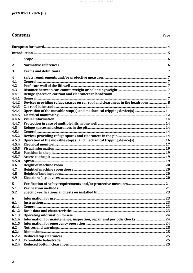
Contents Page
European foreword . 4
Introduction . 5
1 Scope . 6
2 Normative references . 6
3 Terms and definitions . 7
4 Safety requirements and/or protective measures . 7
4.1 General . 7
4.2 Perforate wall of the lift well . 7
4.3 Distance between car, counterweight or balancing weight . 7
4.4 Refuge spaces on car roof and clearances in headroom . 7
4.4.1 General . 7
4.4.2 Devices providing refuge spaces on car roof and clearances in the headroom . 8
4.4.3 Car roof balustrade . 11
4.4.4 Operation of the movable stop(s) and mechanical tripping device(s) . 11
4.4.5 Electrical monitoring . 12
4.4.6 Visual information . 14
4.4.7 Protection in case of multiple lifts in one well . 14
4.5 Refuge spaces and clearances in the pit . 14
4.5.1 General . 14
4.5.2 Devices providing refuge spaces and clearances in the pit. 14
4.5.3 Operation of the movable stop(s) and mechanical tripping device(s) . 16
4.5.4 Electrical monitoring . 17
4.5.5 Visual information . 19
4.5.6 Partition in the pit . 19
4.5.7 Access to the pit . 19
4.5.8 Apron . 19
4.6 Height of machine room . 20
4.7 Height of machine room doors . 20
4.8 Height of landing doors . 20
4.9 Electric safety devices . 20
5 Verification of safety requirements and/or protective measures . 21
5.1 Verification methods . 21
5.2 Specific verifications and tests on installed lift . 23
6 Information for use . 23
6.1 Instructions . 23
6.1.1 General . 23
6.1.2 Basic data and characteristics . 23
6.1.3 Operating information for use . 24
6.1.4 Information for maintenance, inspection, repair and periodic checks . 24
6.1.5 Information for emergency operation . 24
6.2 Notices and warnings . 25
6.2.1 Dimensions . 25
6.2.2 Reduced top clearances . 25
6.2.3 Extendable balustrade . 25
6.2.4 Reduced bottom clearances . 25
6.2.5 Extendable car apron . 25
Annex A (normative) List of the electric safety devices . 26
Annex B (normative) Verification of the mechanical stopping means of the pre-triggered
stopping system . 27
B.1 General provisions . 27
B.2 Test samples . 27
B.3 Testing . 27
B.4 Instructions . 28
Annex ZA (informative) Relationship between this European Standard and the essential
requirements of Directive 2014/33/EU aimed to be covered . 30
Bibliography . 34
European foreword
This document (prEN 81-21:2026) has been prepared by Technical Committee CEN/TC 10 “Lifts,
escalators and moving walks”, the secretariat of which is held by AFNOR.
This document is currently submitted to the CEN Enquiry.
This document will supersede EN 81-21:2022.
— updating of references and their associated requirements with regard to EN ISO 8100-1:2026;
— removal of chapter on counterweight/balancing weight in separate well;
— removal of automatic extending apron;
— update of Annex ZA including a table for Machinery Regulation (EU) 2023/1230.
This document is intended to be used in conjunction with EN ISO 8100-1:2026, which gives the basic
requirements for passenger and goods passenger lifts.
This document is part of the EN 81 series of standards. The structure of the EN 81 series is described in
CEN/TR 81-10:2008.
This document has been prepared under a standardization request addressed to CEN by the European
Commission. The Standing Committee of the EFTA States subsequently approves these requests for its
Member States.
For the relationship with EU Legislation, see informative Annex ZA, which is an integral part of this
document.
Introduction
This document is a type-C standard as stated in EN ISO 12100:2010.
This document is of relevance, in particular, for the following stakeholder groups representing the market
players with regard to machinery safety:
— machine manufacturers (small, medium and large enterprises);
— health and safety bodies (regulators, accident prevention organizations, market surveillance, etc.).
Others can be affected by the level of machinery safety achieved with the means of the document by the
above-mentioned stakeholder groups:
— machine users/employers (small, medium and large enterprises);
— machine users/employees (e.g. trade unions, organizations for people with special needs);
— service providers, e.g. for maintenance (small, medium and large enterprises);
— consumers (in case of machinery intended for use by consumers).
The above-mentioned stakeholder groups have been given the possibility to participate in the drafting
process of this document.
The machinery concerned and the extent to which hazards, hazardous situations or hazardous events are
covered are indicated in the Scope of this document.
When requirements of this type-C standard are different from those which are stated in type-A or type-B
standards, the requirements of this type-C standard take precedence over the requirements of the other
standards for machines that have been designed and built according to the requirements of this type-C
standard.
The main concern dealt with in this document is the reduction of top and pit clearances that may be
required due to site conditions. The adopted principle of safety is based on two levels of achievement:
first by means of an electrical stopping of the lift car, then by means of a mechanical stopping of the lift
car.
In order to have a uniform understanding of the requirements of this document, an existing building
within the terms of this document is understood to be one which was already in use before the lift was
installed. A building whose internal structure is completely renewed is considered as a new building
within the terms of this document.
1 Scope
This document specifies the safety rules related to passenger and goods/passenger lifts installed in
existing buildings or existing wells where limitations enforced by building constraints mean that some
requirements of EN ISO 8100-1:2026 cannot be met.
It addresses the following constraints and gives requirements for alternative solutions:
— existing perforate walls of the lift well;
— reduction in available well are leading to reduced distance between car, counterweight or balancing
weight;
— reduced building dimensions and clearances leading to:
— reductions in available space for headroom and pit;
— reduced car roof balustrade dimensions;
— reduced height of sill apron;
— reduced height of machine and/or pulley room;
— reduced available area for access door/trap door;
— reduction in available height of landing doors.
This document is not applicable to lifts installed before the date of its publication.
2 Normative references
The following documents are referred to in the text in such a way that some or all of their content
constitutes requirements of this document. For dated references, only the edition cited applies. For
undated references, the latest edition of the referenced document (including any amendments) applies.
EN ISO 8100-1:2026, Lifts for the transport of persons and goods — Part 1: Safety rules for the construction
and installation of passenger and goods passenger lifts (ISO 8100-1:2026, including corrected version 2026-
05)
EN ISO 8100-2:2026, Lifts for the transport of persons and goods — Part 2: Design rules, calculations,
verifications and tests of lift components (ISO 8100-2:2026)
EN ISO 12100:2010, Safety of machinery — General principles for design — Risk assessment and risk
reduction (ISO 12100:2010)
EN ISO 13857:2019, Safety of machinery — Safety distances to prevent hazard zones being reached by
upper and lower limbs (ISO 13857:2019)
ISO 3864-1:2011, Graphical symbols — Safety colours and safety signs — Part 1: Design principles for safety
signs and safety markings
ISO 7010:2019, Graphical symbols — Safety colours and safety signs — Registered safety signs
3 Terms and definitions
For the purposes of this document, the terms and definitions given in EN ISO 12100:2010,
EN ISO 8100-1:2026 apply.
ISO and IEC maintain terminology databases for use in standardization at the following addresses:
— ISO Online browsing platform: available at https://www.iso.org/obp/
— IEC Electropedia: available at https://www.electropedia.org/
4 Safety requirements and/or protective measures
4.1 General
Lifts within the scope of this standard shall comply with the relevant safety requirements and/or
protective measures of the following clauses where one or several requirements in EN ISO 8100-1:2026
cannot be fulfilled. In addition, lifts shall be designed according to the principles of EN ISO 12100:2010
for relevant but not significant hazards, which are not dealt with by this document.
4.2 Perforate wall of the lift well
4.2.1 Where the lift is installed in an existing lift well enclosure, which is not imperforate as per
EN ISO 8100-1:2026, 4.2.5.2.1, the minimum distances between the moving parts of the lift and the
openings in the well enclosure shall be in accordance with EN ISO 13857:2019, Table 5 and 4.2.4.3 or
4.2.4.2.
4.2.2 An imperforate screen shall be provided around the landing door locking device(s) where parts
to unlock the locking device can be reached from outside the well by means of a straight, round object
with a length of 300 mm and a diameter of 1 mm.
4.3 Distance between car, counterweight or balancing weight
Where due to existing building constraints the distance between car and counterweight or balancing
weight as per EN ISO 8100-1:2026, 4.2.5.5.3 cannot be fulfilled the following shall apply.
The guidance shall ensure that the car and its associated components shall be at a distance of at least
25 mm from the counterweight or balancing weight and its associated components.
Retaining devices on the car and counterweight or balancing weight shall be provided to maintain the car
and the counterweight or balancing weight guided to avoid collision if the guidance has failed.
The retaining devices shall withstand the horizontal forces in accordance with EN ISO 8100-1:2026,
4.7.2.3.1 a).
4.4 Refuge spaces on car roof and clearances in headroom
4.4.1 General
Where due to existing building constraints the refuge spaces on the car roof and/or clearances in the
headroom as per EN ISO 8100-1:2026, 4.2.5.7 cannot be fulfilled when the car is at its highest position as
per EN ISO 8100-1:2026, 4.2.5.6.1 the requirements from 4.4.2 to 4.4.7 shall apply.
4.4.2 Devices providing refuge spaces on car roof and clearances in the headroom
4.4.2.1 General
4.4.2.1.1 The device(s) providing refuge space on the car roof and clearances in the headroom shall be
either:
a) movable stop(s) as per 4.4.2.2; or
b) a pre-triggered stopping system as per 4.4.2.3.
4.4.2.1.2 The device(s) shall be able to stop the empty car either with:
a) movable stop(s) as per 4.4.2.2 from any speed up to 115 % of the rated speed; or
b) a pre-triggered stopping system as per 4.4.2.3 from any speed up to the maximum tripping speed in
accordance with EN ISO 8100-1:2026, 4.6.6.10 or the maximum speed for hydraulic lifts in
accordance with EN ISO 8100-1:2026, 4.9.3.8.2.
4.4.2.1.3 When the car is at the highest position as per Table 1, the dimensions of the refuge spaces on
the car roof shall be in accordance with EN ISO 8100-1:2026, Table 2 and the clearances in the headroom
shall be in accordance with EN ISO 8100-1:2026, 4.2.5.7.2 a), b), c), d).
Table 1 — Highest position of the car
Device Traction drive Positive drive Hydraulic drive Hydraulic drive
providing (direct) (indirect)
refuge space
Movable Counterweight on Car on fully Ram in its Ram in its
compressed upper ultimate position ultimate position
stop(s) fully compressed
buffer of movable buffer as per achieved through achieved through
(4.4.2.2)
2*
stop + 0,034v as 4.4.2.2.1.2 the means of ram the means of ram
per 4.4.2.2.1.1 a) stroke limitation stroke limitation
as per 4.4.2.2.1.3 as per 4.4.2.2.1.3 +
or
2*
0,034v
car on fully
compressed upper
buffer as per
4.4.2.2.1.1 b)
Pre-triggered Final stopped position
stopping
system
(4.4.2.3)
* 0,034v represents half the gravity stopping distance corresponding to 115 % of the rated speed.
4.4.2.1.4 Inspection and maintenance (see 6.1) of the devices providing refuge space and clearances
shall be possible from a machinery space, the car roof, through an inspection door in accordance with
EN ISO 8100-1:2026, 4.2.3.2, 4.2.3.3, or from the pit.
Where maintenance or inspection work disables the functioning of the mechanical triggering device(s)
or automatic movable stop(s), the following shall apply:
a) A mechanical device shall be provided. When engaged, it shall prevent the movement of the car.
b) The retracted position of the mechanical device shall be checked by an electric safety device.
4.4.2.2 Movable stops
4.4.2.2.1 Arrangement
4.4.2.2.1.1 For traction drive lifts, the movable stop(s) in the extended position shall act on either:
a) the upwards travelling car; or
b) the downwards travelling counterweight, under the condition that the suspension means shall slip
on the traction sheave in accordance with EN ISO 8100-1:2026, 4.5.3.3 a) 1).
4.4.2.2.1.2 For positive drive lifts, the movable stop(s) in the extended position shall act on the
upwards travelling car.
4.4.2.2.1.3 For hydraulic lifts, the movable stop(s) in the extended position shall limit the ram stroke
in accordance with EN ISO 8100-1:2026, 4.9.3.2.3.2.
4.4.2.2.2 Buffering of movable stop(s)
4.4.2.2.2.1 In the case of traction and positive drive lifts the movable stop(s) shall incorporate buffers
or act on buffers of the following type:
a) energy accumulation type buffers in accordance with EN ISO 8100-1:2026, 4.8.1.5 and 4.8.2.1; or
b) energy dissipation type buffers in accordance with EN ISO 8100-1:2026, 4.8.1.6 and 4.8.2.2.
4.4.2.2.2.2 In the case of hydraulic lifts the design of the movable stop(s) shall be in accordance with
EN ISO 8100-1:2026, 4.9.3.2.4.2.
4.4.2.2.3 Strength of movable stop(s)
Movable stop(s) shall withstand the vertical force imposed on them in accordance with
EN ISO 8100-1:2026, 4.2.1.5.5.
4.4.2.2.4 Counterweight screen and movable stop(s)
In accordance with EN ISO 8100-1:2026, 4.2.5.5.1 f) where movable stop(s) are to be placed under the
counterweight, the slots in the screen are permitted to be used for the operation of the movable stop(s).
When the 0,30 m slot width is insufficient to permit the deployment of the movable stop(s) the full screen
or part of the screen may be removed. When the full screen or part of the screen can be removed the
correct installed position of the screen shall be checked by an electric safety device in accordance with
EN ISO 8100-1:2026, 4.11.2.
4.4.2.3 Pre-triggered stopping system
4.4.2.3.1 The pre-triggered stopping system shall consist of:
— a mechanical tripping device; and
— a mechanical stopping means.
4.4.2.3.2 The pre-triggered stopping system shall be in accordance with the following:
a) the mechanical stopping means shall be mounted to the car and act on the guide rails of the car;
b) the mechanical tripping device(s) shall trip the mechanical stopping means:
1) when the car reaches the tripping point; and
2) at any point above the tripping point;
c) the mechanical tripping device(s) shall be capable to produce at least twice the force that is necessary
to engage the mechanical stopping means;
d) the mechanical stopping means shall be tripped by positive mechanical action;
1) where springs are used they shall be of the guided compression type;
2) where a rope is used, it shall have a safety factor of at least 8 related to the tensile force produced
in the rope during the tripping of the mechanical stopping means;
3) the operation force required to trip the mechanical stopping means shall not be generated by
traction;
e) the mechanical stopping means shall remain tripped when the car is at any position above the
tripping point;
f) in case of a release of the mechanical stopping means it shall be re-tripped when the car moves again
in up direction above the tripping point;
g) the retardation by the mechanical stopping means shall be in accordance with EN ISO 8100-1:2026,
4.6.7.6;
h) when the mechanical stopping means has stopped the car the inclination of the floor of the car shall
be in accordance with EN ISO 8100-1:2026, 4.4.3.2.1;
i) the retracted position of the mechanical stopping means shall be checked by an electric safety device
in accordance with EN ISO 8100-1:2026, 4.11.2. This electric safety device is permitted to be
bypassed in in accordance with EN ISO 8100-1:2026, 4.12.1.6.2.1 in emergency electrical operation.
j) when the mechanical stopping means has been engaged and returned to its retracted position, the
return of the lift to automatic operation shall require intentional reset on site as per 6.1. A power
cycle by itself shall not provide this reset;
k) the release of the mechanical stopping means of the pre-triggered stopping system shall not require
access to the well;
l) after the return to the retracted position of the mechanical stopping means, it shall be in a condition
to operate;
m) the pre-triggered stopping system shall be verified in accordance with Annex B;
n) a data plate shall be fixed on the stopping element of the pre-triggered stopping system indicating:
1) the name of the manufacturer;
2) its identification;
3) the limits of the applicable masses;
4) the maximum tripping speed;
5) the minimum height of the characters shall be 2,5 mm.
4.4.3 Car roof balustrade
4.4.3.1 Where a balustrade is required in accordance with EN ISO 8100-1:2026, 4.4.7.2 b) and this
balustrade will collide with the ceiling when the car is at its highest position as per EN ISO 8100-1:2026,
4.2.5.6.1, an extendable balustrade shall be provided on the car roof.
4.4.3.2 The extendable balustrade shall be in accordance with the following:
a) the balustrade in its extended position shall be in accordance with EN ISO 8100-1:2026, 4.4.7.4;
b) the balustrade shall remain in its extended position when a force of 1000 N is applied vertically at
right angles to any point at the top of the balustrade;
c) the balustrade shall be extendable and retractable either from the landing or from a standing area on
the car roof. When extending or retracting the balustrade from the car roof (see 6.1) the standing
area shall be located at a distance of at least 0,5 m from the edge of the car roof where the balustrade
is located;
d) the force needed to extend and to retract the balustrade shall not exceed 150 N.
4.4.4 Operation of the movable stop(s) and mechanical tripping device(s)
4.4.4.1 The movable stop(s) or the mechanical tripping device(s) shall be operated:
a) automatically as per 4.4.5.5; or
b) manually.
4.4.4.2 For traction drive lifts, in the case of manual operation of moveable stop(s) or manual
operation of mechanical tripping device(s), a stopping element in accordance with EN ISO 8100-1:2026,
4.6.7 shall be provided to prevent movement of the car in the up direction. This stopping element shall
be applied when the electric safety device as per 4.4.5.5 is operated and the movable stop(s) or the
mechanical triggering device(s) are not in the extended position.
4.4.4.3 In the case of a power failure to the stopping element as per 4.4.4.2, the stopping element
shall be activated and maintained in the active position at least up to power restoration.
4.4.4.4 In the case of power failure to the automatic movable stop(s) or the automatic mechanical
tripping device(s), they shall be extended and maintained in their extended position at least up to power
restoration.
4.4.5 Electrical monitoring
4.4.5.1 The fully extended (active) position of the movable stop(s) and the triggering device(s) shall
be checked by an electric safety device in accordance with EN ISO 8100-1:2026, 4.11.2.
4.4.5.2 The fully retracted (inactive) position of the movable stop(s) and the triggering device(s)
shall be checked by an electric safety device in accordance with EN ISO 8100-1:2026, 4.11.2.
4.4.5.3 The fully extended (active) position of the extendable balustrade(s), where provided, shall be
checked by an electric safety device in accordance with EN ISO 8100-1:2026, 4.11.2.
4.4.5.4 The fully retracted (inactive) position of the extendable balustrade(s), where provided, shall
be checked by an electric safety device in accordance with EN ISO 8100-1:2026, 4.11.2.
4.4.5.5 The opening by means of a key of an access to the car roof shall:
a) operate an electric safety device in accordance with EN ISO 8100-1:2026, 4.11.2; and
b) operate the automatic movable stop(s) as per 4.4.4.1 a) or the automatic mechanical tripping
device(s) as per 4.4.4.1 a) or the stopping element as per 4.4.4.2 by means of:
1) a safety contact in accordance with EN ISO 8100-1:2026, 4.11.2.2; or
2) a safety circuit in accordance with EN ISO 8100-1:2026, 4.11.2.3; or
3) a SIL-rated circuit in accordance with EN ISO 8100-1:2026 4.11.2.4 with SIL 3; and
c) disable the manual opening of the stopping element as per 4.4.4.2, when the manually operated
movable stop(s) or the manually operated mechanical triggering device(s) are not in the extended
position by means of:
1) a safety contact in accordance with EN ISO 8100-1:2026, 4.11.2.2; or
2) a safety circuit in accordance with EN ISO 8100-1:2026, 4.11.2.3; or
3) a SIL-rated circuit in accordance with EN ISO 8100-1:2026, 4.11.2.4 with SIL 3.
4.4.5.6 The operation as per 4.4.5.5 shall be bi-stable and shall be only reset by the electric reset
device as per 4.4.5.7. A power cycle by itself shall not reset the operation.
When an opening by means of a key of an access to the car roof cannot be detected due to a loss of power
supply, a reset by the electric reset device as per 4.4.5.7 shall be required after the power is restored.
4.4.5.7 The electric reset device shall:
a) be lockable in the inactive position; and
b) located outside the well and accessible only by use of a key; and
c) be provided with an electric safety device in accordance with EN ISO 8100-1:2026, 4.11.2 checking
the inactive position of the reset device.
4.4.5.8 The resetting of the operation as per 4.4.5.5 shall only be possible when:
a) the electric reset device is activated; and
b) the inspection operation switch(es) on the car roof in accordance with EN ISO 8100-1:2026,
4.12.1.5.1.2 a) is in “NORMAL” position; and
c) the stopping device on the car roof in accordance with EN ISO 8100-1:2026, 4.12.1.11.1 a) is not in
the STOP position; and
d) any access to the car roof is closed and locked; and
e) the movable stop(s) or the triggering device(s) are in the retracted position as per 4.4.5.2; and
f) the extendable balustrade, where provided, is in the retracted position as per 4.4.5.4.
4.4.5.9 After the electric safety device as per 4.4.5.5 a) is operated and the car is moving in upwards
direction in inspection operation:
a) an electric safety device in accordance with EN ISO 8100-1:2026 4.11.2 shall be operated before the
car comes into contact with the movable stop(s) and triggering device(s).
The operation of the electric safety device shall be maintained until the buffer(s) of the movable stop(s)
are fully compressed, or the mechanical stopping gear has stopped the car.
b) the car shall stop before the electric safety device as per 4.4.5.9 a) is operated.
4.4.5.10 The electric safety devices as per 4.4.5.1, 4.4.5.2, 4.4.5.3, 4.4.5.4 and 4.4.5.5 a) shall ensure that:
a) operation of the lift while;
— all inspection operation switches are in “NORMAL”, and
— emergency electrical operation switch is in “NORMAL”,
shall only be possible if the electric safety devices as per 4.4.5.2, 4.4.5.4 and 4.4.5.5 a) are not
operated. As required for the operation, the electric safety devices as per 4.4.5.1 and 4.4.5.3 are
permitted to be bypassed by electric safety devices in accordance with EN ISO 8100-1:2026,
4.11.2.
b) operation of the lift while the inspection operation is in “INSPECTION” while 4.4.5.5 a) is operated
shall only be possible if the electric safety devices as per 4.4.5.1 and 4.4.5.3 are not operated. As
required for the operation, the electric safety devices as per 4.4.5.2, 4.4.5.4 and 4.4.5.5 a) are
permitted to be bypassed by electric safety devices in accordance with EN ISO 8100-1:2026, 4.11.2.
c) operation of the lift while the emergency electrical operation switch is in the “ON” position while
4.4.5.5 a) is operated shall only be possible if the electrical safety devices as per 4.4.5.1 and 4.4.5.3
are not operated. As required for the operation, the electric safety devices as per 4.4.5.2, 4.4.5.4 and
4.4.5.5 a) are permitted to be bypassed by electric safety devices in accordance with
EN ISO 8100-1:2026, 4.11.2.
4.4.5.11 For landing doors not mechanically coupled to the car door an additional electric device shall
prevent any movement of the car if this landing door gives access to the car roof and is open. This device
shall not be accessible without using a tool.
4.4.6 Visual information
Before accessing the car roof, it shall be possible to determine if either the movable stop(s) or the
mechanical triggering device(s) are in the extended position as per 6.1.4 a).
4.4.7 Protection in case of multiple lifts in one well
Where the horizontal distance from the edge of the car roof of a lift having reduced top clearances to the
edge of the car roof of an adjacent lift(s) is less than 2,0 m a partition shall prevent access to the lift(s)
having reduced top clearances.
This partition shall be in accordance with the following:
a) If this partition is perforated, it shall be in accordance with EN ISO 13857:2019, 4.2.4.1.
b) The partition shall not deflect to cause the moving parts to collide with it when a force of 300 N being
evenly distributed over an area of 5 cm in round or square section is applied at right angles at any
point of the partition.
c) The partition shall extend through the full height and depth of the well.
4.5 Refuge spaces and clearances in the pit
4.5.1 General
Where due to existing building constraints the refuge spaces and/or clearances in the pit as per
EN ISO 8100-1:2026, 4.2.5.8 cannot be fulfilled when the car is at its lowest position as per
EN ISO 8100-1:2026, 4.2.5.6.1 then 4.5.2 to 4.5.8 shall apply.
4.5.2 Devices providing refuge spaces and clearances in the pit
4.5.2.1 General
4.5.2.1.1 The device(s) providing refuge space and clearances in the pit shall be either:
a) movable stop(s) as per 4.5.2.2; or
b) a pre-triggered stopping system as per 4.5.2.3.
4.5.2.1.2 The device(s) shall be able to stop the car with rated load by:
a) movable stop(s) as per 4.5.2.2 from any speed up to 115 % of the rated speed; or
b) a pre-triggered stopping system as per 4.5.2.3 from any speed up to the maximum tripping speed in
accordance with EN ISO 8100-1:2026, 4.6.2.2.1.1 or the maximum tripping speed for hydraulic lifts
in accordance with EN ISO 8100-1:2026, 4.6.2.2.1.1 or 4.6.3.1 or 4.6.4.1 or the tripping speed of the
safety gear in accordance with EN ISO 8100-1:2026, 4.6.2.2.2 d) or 4.6.2.2.3 h) as applicable.
4.5.2.1.3 When the car rests on the fully compressed buffers as per 4.5.2.2 or when the car is stopped
by the pre-triggered stopping system, the dimensions of the refuge spaces in the pit shall be in accordance
with EN ISO 8100-1:2026, Table 3 and the clearances in the pit shall be in accordance with
EN ISO 8100-1:2026, 4.2.5.8.
4.5.2.1.4 Inspection and maintenance (see 6.1) of the devices providing refuge space and clearances
shall be possible from a machinery space, the car roof, through an inspection door in accordance with
EN ISO 8100-1:2026, 4.2.3 or from the pit.
Where maintenance or inspection work disables the functioning of the mechanical triggering device(s)
or automatic movable stop(s), the following shall apply:
a) a mechanical device shall be provided. When engaged it shall prevent movement of the car;
b) the retracted position of the mechanical device shall be checked by an electric safety device.
4.5.2.2 Movable stop(s)
4.5.2.2.1 Arrangement
The movable stop(s) shall be installed in the pit and in the extended position act on the downwards
travelling car.
4.5.2.2.2 Buffering of movable stop(s)
The movable stop(s) shall incorporate buffers or act on buffers of the following type:
a) energy accumulation type buffers in accordance with EN ISO 8100-1:2026, 4.8.1.5 and 4.8.2.1; or
b) energy dissipation type buffers in accordance with EN ISO 8100-1:2026, 4.8.1.6 and 4.8.2.2.
4.5.2.2.3 Strength of movable stop(s)
Movable stop(s) shall withstand the vertical force imposed on them in accordance with
EN ISO 8100-1:2026, 4.2.1.5.5.
4.5.2.3 Pre-triggered stopping system
4.5.2.3.1 The pre-triggered stopping system shall consist of:
— a mechanical tripping device; and
— a mechanical stopping means.
4.5.2.3.2 The pre-triggered stopping system shall be in accordance with the following:
a) the mechanical stopping means shall be mounted to the car and act on the guide rails of the car;
b) the mechanical tripping device(s) shall trip the mechanical stopping means:
1) when the car reaches the tripping point; and
2) at any point below the tripping point;
c) the mechanical tripping device(s) shall be capable to produce at least twice the force that is necessary
to engage the mechanical stopping means;
d) the mechanical stopping means shall be tripped by positive mechanical action;
1) where springs are used they shall be of the guided compression type;
2) where a rope is used, it shall have a safety factor of at least 8 related to the tensile force produced
in the rope during the tripping of the mechanical stopping means;
3) the operation force required to trip the mechanical stopping means shall not be generated by
traction;
e) the mechanical stopping means shall remain tripped when the car is at any position below the
tripping point;
f) in case of a release of the mechanical stopping means it shall be re-tripped when the car moves again
in down direction below the tripping point;
g) the retardation by the mechanical stopping means shall be in accordance with EN ISO 8100-1:2026,
4.6.7.6;
h) when the mechanical stopping means has stopped the car the inclination of the floor of the car shall
be in accordance with EN ISO 8100-1:2026, 4.4.3.2.1;
i) the retracted position of the mechanical stopping means shall be checked by an electric safety
device in accordance with EN ISO 8100-1:2026, 4.11.2. This electric safety device is permitted to be
bypassed in accordance with EN ISO 8100-1:2026, 4.12.1.6.2.1 in emergency electrical operation.
j) when the mechanical stopping means has been engaged and returned to its retracted position, the
return of the lift to automatic operation shall require intentional reset on site as per 6.1.4 e). A power
cycle by itself shall not provide this reset;
k) the release of the mechanical stopping means of the pre-triggered stopping system shall not require
access to the well;
l) after the return to the retracted position of the mechanical stopping means, it shall be in a condition
to operate;
m) the pre-triggered stopping system shall be verified in accordance with Annex B.
n) a data plate shall be fixed on the stopping element of the pre-triggered stopping system indicating:
1) the name of the manufacturer;
2) its identification;
3) the limits of the applicable masses;
4) the maximum tripping speed;
5) the minimum height of the characters shall be 2,5 mm.
4.5.3 Operation of the movable stop(s) and mechanical tripping device(s)
4.5.3.1 The movable stop(s) or the mechanical tripping device(s) shall be operated:
a) automatically as per 4.5.4.3; or
b) manually.
4.5.3.2 In the case of manual operation of moveable stop(s) or manual operation of mechanical
tripping device(s), a stopping element in accordance with EN ISO 8100-1:2026, 4.6.7 shall be provided to
prevent movement of the car in the down direction. This stopping element shall be applied when the
electric safety device as per 4.5.4.3 is operated and the movable stop(s) or the mechanical triggering
device(s) are not in the extended position.
4.5.3.3 In the case of a power failure to the stopping element as per 4.5.3.2, the stopping element
shall be activated and maintained in the active position at least up to power restoration.
4.5.3.4 In the case of power failure to the automatic movable stop(s) or the automatic mechanical
tripping device(s), they shall be extended and maintained in their extended position at least up to power
restoration.
4.5.4 Electrical monitoring
4.5.4.1 The fully extended (active) position of the movable stop(s) and the triggering device(s) shall
be checked by an electric safety device in accordance with EN ISO 8100-1:2026, 4.11.2.
4.5.4.2 The fully retracted (inactive) position of the movable stop(s) and the triggering device(s)
shall be checked by an electric safety device in accordance with EN ISO 8100-1:2026, 4.11.2.
4.5.4.3 The opening by means of a key of an access to the pit shall:
a) operate an electric safety device in acco
...