

EN IEC 60730-1:2024/FprA1:2026
(Amendment)Automatic electrical controls - Part 1: General requirements
- Status
- Not Published
- Publication Date
- 07-Feb-2027
- Technical Committee
- CLC/TC 72 - Automatic controls for household use
- Current Stage
- 5020 - Vote circulated - Formal Approval
- Start Date
- 25-Sep-2026
- Due Date
- 31-Jul-2026
- Completion Date
- 25-Sep-2026

EN IEC 60730-1:2024/FprA1:2026 is a CENELEC amendment to IEC 60730-1 for automatic electrical controls. It updates the general requirements for controls used in household applications, with a strong focus on insulation coordination, construction, fault assessment, endurance, fire performance and EMC-related tests. Engineers, quality teams, buyers and test labs use it to check which control functions, materials, dimensions and test conditions apply.
What does EN IEC 60730-1:2024/FprA1:2026 specify?
EN IEC 60730-1:2024/FprA1:2026 specifies amendments to the general requirements for automatic electrical controls. The amendment updates the voltage limits, insulation language, technical information, test methods and annex material used to assess controls against safety and EMC expectations.
The document is organized as an amendment to the main standard. It revises Clause 1 Scope, Clause 2 Normative references, Clause 3 Terms and definitions, Clause 5 Required technical information, Clauses 8, 9, 11, 12, 13, 19 and 21, and it updates Annexes C, H, J, M, N, O and Q while adding Annex U.
| Annex | What it covers |
|---|---|
| C | Nominal voltages of supply systems for different modes of overvoltage control |
| H | Requirements related to functional safety and EMC immunity information and tests |
| J | Requirements for thermistor elements and controls using thermistors |
| M | Printed circuit board protection |
| N | Explanatory notes for surge immunity test |
| O | Guidance for applying Clause 11 |
| Q | Regional differences relevant for CENELEC member countries |
| U | Requirements related to Class Ae control functions |
What are the key requirements of EN IEC 60730-1:2024/FprA1:2026?
EN IEC 60730-1:2024/FprA1:2026 mainly tightens how controls are specified and how their insulation, software, and fault behaviour are checked. The practical effect is that the manufacturer has to declare more design information and prove more of the electrical and environmental robustness of the control.
Voltage, insulation and creepage
Clause 1 updates the scope so the standard applies to AC or DC powered controls up to the stated rated-voltage ceiling. Clause 11 then aligns insulation coordination with the updated 2025 edition of IEC 60664-1 and replaces the old wording around rated impulse voltage with rated impulse withstand voltage.
For clearances, Clause 11 now points designers to the largest applicable requirement, including mains-connected cases and steady-state or recurring peak voltage cases. In practice, this means internal voltage transients and recurring peaks must be considered in the insulation design, not only the nominal supply.
For creepage distances, Clause 11 separates the treatment of mains-fed equipment from equipment fed by isolated or alternative sources. The amendment also extends the creepage tables to higher voltages, which matters for product families that operate at higher internal voltages or use different supply systems.
Required technical information and construction
Clause 5 expands the information that must be declared in Table 1, including items linked to enclosure specification, cable length, and class Ae control functions. This matters because the declared information drives which tests and exemption paths are allowed later in the standard.
Clause 9 strengthens constructional requirements for protective impedance and short-circuit capability of the supply when overcurrent protective devices are used. It also points software-based controls to Annex U when they include Ae functions, so software claims and validation evidence must match the declared class.
Clause 8 updates terminal and termination references so the correct Table 1 requirement is used. For a reader, that means terminal design and marking have to be checked against the updated declaration structure, not only against a generic clause reference.
Fault assessment, endurance and fire behaviour
Clause 13 updates the fault assessment procedure for electronic circuits, including the way enclosures and tissue paper are used in the test set-up for integrated and incorporated controls. The amendment also revises how integrated circuits, relays and switches are treated in the fault-mode table, including when short-circuit modes are excluded.
Clause 19 updates endurance testing so the method of operation, changing quantity and overshoot are handled according to the declared values in Table 1. In practice, endurance testing must reflect the actual operating mode of the control, especially for sensing controls and type 2 action.
Clause 21 revises the resistance-to-heat, fire and tracking requirements. The amendment sets out when glow-wire testing is not needed because the material already has the declared GWFI or HB40 classification, and it adds stronger conditions for parts that retain electrical connections. That helps manufacturers choose materials and justify exemptions with the right material classification evidence.
EMC and surge immunity
Annex H updates the information and test requirements for functional safety and EMC immunity. It adds declarations for cable length limits and distinguishes between different cable and interface cases, which affects which immunity tests apply.
Annex H also updates the surge, electrical fast transient/burst and conducted disturbance tests. The practical result is that EMC testing must be matched to the declared installation class, cable length and operating mode, especially for interface cables and signal/data/control lines.
What terms does EN IEC 60730-1:2024/FprA1:2026 define?
EN IEC 60730-1:2024/FprA1:2026 updates several voltage and control terms so the insulation and safety rules can be applied consistently.
- Working voltage - the voltage used to characterize the electrical stress across insulation under operating conditions.
- Impulse withstand voltage - the highest impulse peak that insulation can withstand without breakdown under specified conditions.
- Rated impulse withstand voltage - the impulse withstand value assigned by the manufacturer to the equipment or part.
- Steady-state working voltage - the working voltage after transient overvoltage effects have disappeared, ignoring short-term variations.
- Steady-state peak voltage - the peak value of the steady-state working voltage.
- Recurring peak voltage - periodic voltage peaks caused by waveform distortion or AC components superimposed on DC.
- Operating control - a control type that can provide class A, class Ae, class B or class C control functions.
- Class Ae control function - a control function not intended to be relied upon for safety, but evaluated against the declared specifications.
Who uses EN IEC 60730-1:2024/FprA1:2026?
EN IEC 60730-1:2024/FprA1:2026 is used by control manufacturers, appliance designers, safety engineers, EMC laboratories and conformity assessment teams. It is especially relevant for automatic controls used in household applications such as thermostats, humidity controls, lighting controls, timers, time switches, thermal cut-outs and burner controls.
Quality managers and buyers use it to check what information a supplier must declare and what evidence supports the declared control class. Test laboratories use it to choose the right insulation, endurance, fault and EMC tests. Regional compliance teams also use Annex Q when national differences matter.
What changed in EN IEC 60730-1:2024/FprA1:2026 from the previous edition?
EN IEC 60730-1:2024/FprA1:2026 is Amendment 1 to IEC 60730-1, project IEC 60730-1/AMD1 ED6. The amendment updates the technical basis for insulation coordination, adds and revises definitions, introduces class Ae control functions in Annex U, revises technical information requirements, and updates the EMC, fire and fault-testing clauses.
It also replaces several references with newer editions, including IEC 60664-1:2025, and aligns related tables and annexes with the updated terminology and test approach.
Which standards are used with EN IEC 60730-1:2024/FprA1:2026?
- IEC 60664-1:2025 - provides the updated insulation coordination basis for clearances, creepage distances and overvoltage categories.
- IEC TR 60664-2-2 - is one of the updated normative references connected with insulation coordination practice.
- IEC 63044-5-2 and IEC 63044-5-3 - are the updated EMC-related references named in Clause 2.
- IEC 62368-1:2023 - is used for the resistor requirements accepted for protective impedance.
- IEC 60695-2-12 and IEC 60695-2-13 - provide GWFI and GWIT classifications used to justify glow-wire exemptions.
- IEC 60695-11-10 - provides HB40 classification used in the fire-test exemptions.
- ISO 9772 - provides the HBF requirement for soft or foamy materials when glow-wire testing is not applicable.
- IEC 60669-2-1 - is used for marking switching outputs with micro-gap or semiconductor switching symbols.
- IEC 61000-4-5 - is the surge test method referenced for impulse application in Annex H.
- IEC 60050-851:2008 and IEC 60050-442:2014 - provide source definitions used for voltage terminology.
What does the EN IEC 60730-1:2024/FprA1:2026 document contain?
EN IEC 60730-1:2024/FprA1:2026 contains amended tables, updated definitions, revised test procedures and new annex text for general automatic electrical controls. The practical content includes insulation tables, creepage and clearance methods, fault-mode tables for electronic components, endurance procedures, fire-test exemptions and EMC immunity settings.
It also contains guidance tables for supply-system voltages, declared information for control functions and interface cables, and regional notes for CENELEC member countries. For design and certification work, the most important parts are the updated Table 1 declarations, the insulation tables in Clause 11, the fault assessment in Clause 13, the endurance method in Clause 19 and the EMC material in Annex H.
Relations
- Effective Date
- 25-Feb-2025
Frequently Asked Questions
EN IEC 60730-1:2024/FprA1:2026 is a draft published by CLC. Its full title is "Automatic electrical controls - Part 1: General requirements". This standard covers: Automatic electrical controls - Part 1: General requirements
Automatic electrical controls - Part 1: General requirements
EN IEC 60730-1:2024/FprA1:2026 is classified under the following ICS (International Classification for Standards) categories: 97.120 - Automatic controls for household use. The ICS classification helps identify the subject area and facilitates finding related standards.
EN IEC 60730-1:2024/FprA1:2026 has the following relationships with other standards: It is inter standard links to EN IEC 60730-1:2024. Understanding these relationships helps ensure you are using the most current and applicable version of the standard.
EN IEC 60730-1:2024/FprA1:2026 is available in PDF format for immediate download after purchase. The document can be added to your cart and obtained through the secure checkout process. Digital delivery ensures instant access to the complete standard document.
Standards Content (Sample)
SLOVENSKI STANDARD
01-marec-2026
Avtomatske električne krmilne naprave - 1. del: Splošne zahteve
Automatic electrical controls - Part 1: General requirements
Ta slovenski standard je istoveten z: EN IEC 60730-1:2024/prA1:2026
ICS:
97.120 Avtomatske krmilne naprave Automatic controls for
za dom household use
2003-01.Slovenski inštitut za standardizacijo. Razmnoževanje celote ali delov tega standarda ni dovoljeno.
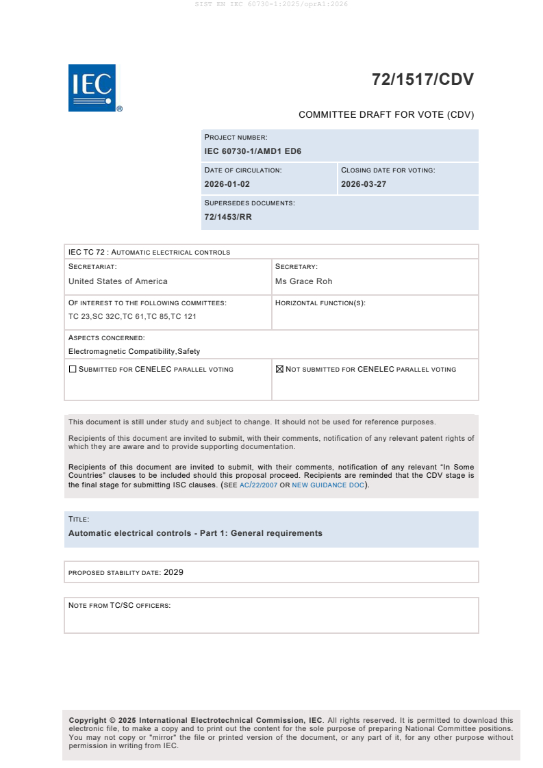
72/1517/CDV
COMMITTEE DRAFT FOR VOTE (CDV)
PROJECT NUMBER:
IEC 60730-1/AMD1 ED6
DATE OF CIRCULATION: CLOSING DATE FOR VOTING:
2026-01-02 2026-03-27
SUPERSEDES DOCUMENTS:
72/1453/RR
IEC TC 72 : AUTOMATIC ELECTRICAL CONTROLS
SECRETARIAT: SECRETARY:
United States of America Ms Grace Roh
OF INTEREST TO THE FOLLOWING COMMITTEES: HORIZONTAL FUNCTION(S):
TC 23,SC 32C,TC 61,TC 85,TC 121
ASPECTS CONCERNED:
Electromagnetic Compatibility,Safety
SUBMITTED FOR CENELEC PARALLEL VOTING NOT SUBMITTED FOR CENELEC PARALLEL VOTING
This document is still under study and subject to change. It should not be used for reference purposes.
Recipients of this document are invited to submit, with their comments, notification of any relevant patent rights of
which they are aware and to provide supporting documentation.
Recipients of this document are invited to submit, with their comments, notification of any relevant “In Some
Countries” clauses to be included should this proposal proceed. Recipients are reminded that the CDV stage is
the final stage for submitting ISC clauses. (SEE AC/22/2007 OR NEW GUIDANCE DOC).
TITLE:
Automatic electrical controls - Part 1: General requirements
PROPOSED STABILITY DATE: 2029
NOTE FROM TC/SC OFFICERS:
electronic file, to make a copy and to print out the content for the sole purpose of preparing National Committee positions.
You may not copy or "mirror" the file or printed version of the document, or any part of it, for any other purpose without
permission in writing from IEC.
IEC CDV 60730-1/AMD1 © IEC 2025
1 INTERNATIONAL ELECTROTECHNICAL COMMISSION
2 ____________
4 AUTOMATIC ELECTRICAL CONTROLS –
6 Part 1: General requirements
8 AMENDMENT 1
10 FOREWORD
11 1) The International Electrotechnical Commission (IEC) is a worldwide organization for standardization comprising
12 all national electrotechnical committees (IEC National Committees). The object of IEC is to promote international
13 co-operation on all questions concerning standardization in the electrical and electronic fields. To this end and
14 in addition to other activities, IEC publishes International Standards, Technical Specifications, Technical Reports,
15 Publicly Available Specifications (PAS) and Guides (hereafter referred to as “IEC Publication(s)”). Their
16 preparation is entrusted to technical committees; any IEC National Committee interested in the subject dealt with
17 may participate in this preparatory work. International, governmental and non-governmental organizations liaising
18 with the IEC also participate in this preparation. IEC collaborates closely with the International Organization for
19 Standardization (ISO) in accordance with conditions determined by agreement between the two organizations.
20 2) The formal decisions or agreements of IEC on technical matters express, as nearly as possible, an international
21 consensus of opinion on the relevant subjects since each technical committee has representation from all
22 interested IEC National Committees.
23 3) IEC Publications have the form of recommendations for international use and are accepted by IEC National
24 Committees in that sense. While all reasonable efforts are made to ensure that the technical content of IEC
25 Publications is accurate, IEC cannot be held responsible for the way in which they are used or for any
26 misinterpretation by any end user.
27 4) In order to promote international uniformity, IEC National Committees undertake to apply IEC Publications
28 transparently to the maximum extent possible in their national and regional publications. Any divergence between
29 any IEC Publication and the corresponding national or regional publication shall be clearly indicated in the latter.
30 5) IEC itself does not provide any attestation of conformity. Independent certification bodies provide conformity
31 assessment services and, in some areas, access to IEC marks of conformity. IEC is not responsible for any
32 services carried out by independent certification bodies.
33 6) All users should ensure that they have the latest edition of this publication.
34 7) No liability shall attach to IEC or its directors, employees, servants or agents including individual experts and
35 members of its technical committees and IEC National Committees for any personal injury, property damage or
36 other damage of any nature whatsoever, whether direct or indirect, or for costs (including legal fees) and
37 expenses arising out of the publication, use of, or reliance upon, this IEC Publication or any other IEC
38 Publications.
39 8) Attention is drawn to the Normative references cited in this publication. Use of the referenced publications is
40 indispensable for the correct application of this publication.
41 9) Attention is drawn to the possibility that some of the elements of this IEC Publication may be the subject of patent
42 rights. IEC shall not be held responsible for identifying any or all such patent rights.
43 Amendment 1 to IEC 60730-1 has been prepared by IEC technical committee 72: Automatic
44 electrical controls. It is an International Standard.
45 The text of this Amendment is based on the following documents:
Draft Report on voting
61/XX/XXXX 61/XX/XXX
47 Full information on the voting for its approval can be found in the report on voting indicated in
48 the above table.
49 The language used for the development of this Amendment is English.
IEC CDV 60730-1/AMD1 © IEC 2025
50 This document was drafted in accordance with ISO/IEC Directives, Part 2, and developed in
51 accordance with ISO/IEC Directives, Part 1 and ISO/IEC Directives, IEC Supplement, available
52 at www.iec.ch/members_experts/refdocs. The main document types developed by IEC are
53 described in greater detail at www.iec.ch/publications/.
54 The committee has decided that the contents of this document will remain unchanged until the
55 stability date indicated on the IEC website under webstore.iec.ch in the data related to the
56 specific document. At this date, the document will be
57 • reconfirmed,
58 • withdrawn, or
59 • revised.
IEC CDV 60730-1/AMD1 © IEC 2025
61 1 Scope
62 Replace the text of the fifth bullet with the following:
63 that are AC or DC powered controls with a rated voltage not exceeding 1000V AC or 1500
64 VDC;2
65 2 Normative references
2 2
66 Replace IEC 60664-1: 2007 with “IEC 60664-1:2025” and delete footnote .
67 Replace “IEC 60664-2 (all parts)” with “IEC TR 60664-2-2”.
68 Replace “IEC 63044 (all parts)” with “IEC 63044-5-2” and “IEC 63044-5-3”.
69 3 Terms and definitions
70 3.1 Definitions relating to ratings, voltages, currents, frequencies, and wattages
71 3.1.3
72 working voltage
73 Add source information to the definition of 3.1.3 after the Note 2 to entry:
74 [SOURCE: IEC 60050-8512008, 851-12-31]
76 Replace the text of 3.1.10 with the following and delete Note 1 to entry:
77 3.1.10
78 impulse withstand voltage
79 highest peak value of impulse voltage of specified form and polarity which does not cause
80 breakdown of insulation under specified conditions.
81 Add the following new definitions:
82 3.1.14
83 rated impulse withstand voltage
84 Value of the impulse withstand voltage assigned by the manufacturer to the equipment or to a
85 part of it, characterizing the specified withstand capability of its insulation against transient
86 overvoltages.
87 [SOURCE: IEC 60664-1: 3.1.19]
89 3.1.14
90 steady-state working voltage
91 working voltage after the transient overvoltage phenomena have subsided and not taking
92 into account short-term voltage variations.
93 [SOURCE: IEC 60664-1: 3.1.8]
94 3.1.16
95 steady-state peak voltage
96 Peak value of the steady-state working voltage.
IEC CDV 60730-1/AMD1 © IEC 2025
97 Note 1 to entry: The peak value of steady-state working voltage across the insulation with the equipment supplied
98 at the rated voltage is considered. The steady-state peak voltage of internal circuits is a direct consequence of the
99 design of products.
100 Note 2 to entry: The steady-state working voltage and the steady-state peak voltage are a long-term voltage
101 stress
102 [SOURCE: IEC 60664-1: 3.1.9]
103 3.1.17
104 recurring peak voltage
105 maximum peak value of periodic excursions of the voltage waveform resulting from distortions
106 of an AC voltage or from AC components superimposed on a DC voltage
107 Note 1 to entry: Random overvoltages, for example due to occasional switching, are not considered to be recurring
108 peak voltages.
109 [SOURCE: IEC 60050-442:2014, 442-09-15]
110 3.2 Definitions of types of control according to purpose
111 3.2.15
112 Operating control
113 Replace the Note 1 to entry with the following:
114 Note 1 to entry: This operating control can provide class A, class Ae, class B or class C control functions.
116 5 Required technical information
m
117 Add in Table 1 item 22, footnote at the end of the sentence.
118 Replace in Table 1 Row 31 “H.17, 19” with “19.7.3, 19.9.3, H.17.5.5” in the third column:
119 Add in Table 1 Row 32 “19.7.4” and “19.9.3” in the third column:
120 Replace “12.2” in Table 1, item 43, column 3 by “12.5”
121 Add the following row 43a to Table 1:
43a signal, data, control and other I/O cables when well separated according to 12.5.1, D or E
installation class 2 H.25.8.1,
H.25.8.3,
Annex N.3
122 Replace in Table 1, Row 55 “rated impulse voltage” with “rated impulse withstand voltage”.
123 Replace in Table 1, Row 60 “rated impulse voltage” with “rated impulse withstand voltage”.
a”
124 Add in Table 1 Row 61 “footnote after Table 14
125 Add in Table 1, row 86, the term “or Ae” after class A in the second column
126 Add the following rows 88 and 89 in Table 1.
l
88 Specification of enclosure in accordance with 13.1.3.2, item h) 13.1.3.2 D
89 Electronic controls of class Ae control functions 3.2.15, 13.1.3.3, D or E
Table H.12,
Annex U,
IEC CDV 60730-1/AMD1 © IEC 2025
127 Add the followings footnote l and m to Table 1:
l
128 The specifications of the enclosure includes material, dimensions, etc
m
129 A control containing a switching output that complies with the requirements of IEC 60669-2-1 for either micro-gap
130 construction (corresponding to micro disconnection, see clause 3.4.3) or semiconductor switching (corresponding
131 to electronic disconnection, see clause 3.4.6) may be marked with a "µ" or "ɛ" respectively, as defined in IEC
132 60669-2-1.
134 8 Terminals and terminations
135 8.2.4.4
136 In the third paragraph, replace “7.2” with “Table 1, requirement 39”.
137 9 Constructional requirements
138 9.2.5 Protective impedance
139 Replace the sentence after the first dashed item in clause 9.2.5 as follows:
140 Alternatively, the resistors shall comply with the requirements of IEC 62368-1:2023, clauses G.10.1,
141 G.10.2, G.10.3.
142 9.3.5.2.1
143 Replace a) with the following:
144 a) when overcurrent protection devices are used as the protective measure, the power supply
145 to the control shall have the capability of supplying a short-circuit current of at least
146 – 500 A, if the control is mains connected,
147 – the maximum capacity of the supply, if the control is not mains connected.
149 9.12 Controls using software
150 Add the following text to 9.12.
151 For Ae control functions, see U.9.12
152 11 Creepage distances, clearances and distances through solid insulation
153 11.1 General
154 Add the following after the last paragraph of 11.1
155 Due to the intended operation modes of specific products, internally generated voltages can
156 also include recurring peaks superimposed to the working voltage. These recurring peaks
157 voltages shall be considered when applying the concept of insulation coordination.
158 Insulation coordination with regard to recurring peak voltage shall consider that partial
159 discharges can occur in solid insulation or along surfaces of insulation.
IEC CDV 60730-1/AMD1 © IEC 2025
160 11.2 Clearances
161 Replace the first paragraph of 11.2.1 with the following:
162 11.2.1
163 Clearances shall be dimensioned to withstand the largest of the following:
164 – For circuits directly connected to the mains supply, the values shown in Table 11 for
165 case A, taking into account the pollution degree and the rated impulse withstand voltage
166 required to serve the overvoltage categories of Table 10.
167 – For a steady-state peak voltage or a recurring peak voltage, the values determined from
168 Table F.8 of IEC 60664-1:2025
169 For basic insulation and functional insulation, smaller distances can be used if the control
170 meets the impulse withstand test of 11.2.14 and the parts are rigid or held by mouldings, or if
171 the construction is such that there is no likelihood of the distances being reduced by distortion
172 or by movement of the parts (for example, during operation or during assembly), but in no case
173 shall the clearances be less than the values shown in Table 11 for case B.
174 Due to intended operation modes of specific controls, internally generated voltages can include
175 recurring peaks superimposed on the working voltage. In such cases, partial discharges can
176 occur in solid insulation or along surfaces of insulation. For peak voltage values greater than
177 2,5 kV, Table F.9 of IEC 60664-1:2025 shall be used to determine the minimum clearance
178 distance.
179 Table 10 – Rated impulse voltage for equipment energized directly from the supply
180 mains (from IEC 60664-1:2007, Table F.1)
181 Replace in the title of Table 10 “IEC 60664-1:2007” with “IEC 60664-1:2025”.
182 Replace in the title of Table 10 “Rated impulse voltage” with “Rated impulse withstand voltage”.
183 Replace “Rated impulse voltage” with “Rated impulse withstand voltage in column 3 of Table
184 10
nd
185 Replace “Rated impulse voltage” with “Rated impulse withstand voltage in the 2 line of
186 footnote (b) in Table 10.
nd
187 Replace “Rated impulse voltage” with “Rated impulse withstand voltage in the 2 line of
188 footnote (d) in Table 10.
190 Table 11 – Clearances for insulation co-ordination (from IEC 60664-1:2007, Table F.2)
191 Replace in the title of Table 11 “IEC 60664-1:2007” with “IEC 60664-1:2025”.
192 Replace in Table 11, footnote b) “IEC 60664-1:2007” with” IEC 60664-1:2025”.
193 Replace “Rated impulse voltage” with impulse withstand voltage” in column 1 of Table 11.
194 Replace “Rated impulse voltage” with “rated impulse withstand voltage” in footnote (a) of Table
195 11.
196 Add the following text in footnote (a) of Table 11 as a new paragraph.
IEC CDV 60730-1/AMD1 © IEC 2025
197 For circuits directly connected to the mains supply, the required impulse withstand voltage is
198 the rated impulse withstand voltage.
199 Add the following entries after the last entry in Table 11:
b
Impulse Clearances in air up to 2000 m above sea level
withstand
Case A Case B
voltage
from
(impulse test required – see 11.2.14)
a
Table 10
c c
Pollution degree Pollution degree
kV
1 2 3 4 1 2 3 4
10 11 11 11 11 3,5 3,5 3,5 3,5
12 14 14 14 14 4,5 4,5 4,5 4,5
15 18 18 18 18 5,5 5,5 5,5 5,5
20 25 25 25 25 8,0 8,0 8,0 8,0
25 33 33 33 33 10 10 10 10
30 40 40 40 40 12,5 12,5 12,5 12,5
40 60 60 60 60 17 17 17 17
50 75 75 75 75 22 22 22 22
60 90 90 90 90 27 27 27 27
80 130 130 130 130 35 35 35 35
100 170 170 170 170 45 45 45 45
201 11.2.2
202 Replace “rated impulse voltage” with “rated impulse withstand voltage” in the first sentence.
203 11.2.3
204 Replace “rated impulse voltage” with “rated impulse withstand voltage” in the first sentence.
205 11.2.11
206 Replace “rated impulse voltage” with “rated impulse withstand voltage” in the first sentence.
207 11.2.12
208 Replace “rated impulse voltage” with “rated impulse withstand voltage” in the second and fourth
209 paragraphs.
210 Replace “IEC 60664-1:2007” with “IEC 60664-1:2025”in the third paragraph.
211 Delete the fourth paragraph from 11.2.12.
Note of the Secretary: Table 10 and Table 11 were updated for higher rated impulse voltage.
Therefore, the sentence in 11.2.12 “Annex F, Table F.2. of IEC 60664-1:2007 gives clearance
dimensions for higher rated impulse voltage” can be deleted.
213 11.2.14
IEC CDV 60730-1/AMD1 © IEC 2025
214 Replace “IEC 60664-1:2007” with “IEC 60664-1:2025” in the first sentence.
215 11.2.15
216 Replace “rated impulse voltage” with “rated impulse withstand voltage” in the first paragraph
217 and in the NOTE.
nd
218 Replace the 2 paragraph as follows:
219 For circuits supplied with a voltage lower than rated voltage, for example, on the secondary
220 side of a transformer, clearances of functional insulation are based on the steady-state
221 working voltage, which is used as the nominal voltage for Table 10.
222 11.3 Creepage distances
223 Replace the first paragraph of 11.3.2 as follows:
224 11.3.2 Creepage distances for basic insulation shall not be less than those specified in Table
225 13 taking into account the material group and the pollution degree.
226 – For equipment energized directly from the low-voltage mains, the creepage distances shall
227 be based on the rationalized voltages of Tables 12a or 12b corresponding to the nominal
228 voltage of the mains supply;
229 – For equipment and internal circuits not energized directly from the low-voltage mains
230 (energized by means such as fuel cell, battery, galvanically-isolated double/reinforced
231 insulated transformers and similar power sources), the creepage distances shall be based
232 on the voltages of Table 13. In such cases, the highest steady-state working voltage (RMS
233 value of the AC or DC value) across the insulation with the equipment supplied at the rated
234 voltage shall be considered.
235 NOTE This kind of steady-state working voltage can be lower, equal or higher than the rated voltage of the
236 equipment. The steady-state working voltage of internal circuits is a direct consequence of the design of
237 products and might be significantly higher than the value of rated voltage.
238 When the steady-state working voltage is used for dimensioning, it is allowed to
239 interpolate values for intermediate voltages. When interpolating, linear interpolation shall
240 be used and values shall be rounded to the same number of digits as the values picked up
241 from the tables.
242 11.3.3 Replace the first paragraph of 11.3.3. with the following:
243 Creepage distances for functional insulation shall not be less than those specified in Table
244 13 for steady-state working voltage, taking into account the material group and the pollution
245 degree.
246 When the steady-state working voltage is used for dimensioning, it is allowed to interpolate
247 values for intermediate voltages. When interpolating, linear interpolation shall be used and
248 values shall be rounded to the same number of digits as the values picked up from the tables.
250 Replace Table 12 with the following tables:
IEC CDV 60730-1/AMD1 © IEC 2025
251 Table 12a – Single-phase three or two-wire a.c. or d.c. systems
252 (from Table F.3 of IEC 60664-1:2020)
Nominal voltage of the supply Voltages rationalized for Table 13
system
a) a)
For insulation line-to-line For insulation line-to-earth
All systems Three-wire systems, mid-point
earthed
V
V
V
12,5 12,5
25 25
30 32
48,
b)
50 50
60 63
30-60 63 32
b)
100 100
110 125
b)
150 160
200 200
100-200 200 100
220 250
110-220
120-240 250 125
b)
300 320
220-440 500 250
b)
600 630
480-960 1000 500
b)
1000 1000
b) c)
1500 1500
a
Line-to-earth insulation level for unearthed or impedance-earthed systems equals that for line-to-line because
the operating voltage to earth of any line can, in practice, approach full line-to-line voltage. This is because
the actual voltage to earth is determined by the insulation resistance and capacitive reactance of each line to
earth; thus, low (but acceptable) insulation resistance of one line can in effect earth it and raise the other two
to full line-to-line voltage to earth.
b
These values correspond to the values given in Table 10
c
For DC values only
IEC CDV 60730-1/AMD1 © IEC 2025
254 Table 12b – Three-phase four or three-wire a.c systems
255 (from Table F.4 of IEC 60664-1:2020)
Nominal voltage of the supply Voltages rationalized for Table 13
system
For insulation line- For insulation line-to-earth
line-to-line to-line
All systems Three-phase four-wire Three-phase, three-wire
a)
systems neutral-earthed systems unearthed or
b)
corner-earthed
V V
V
V
60 63 32 63
120 125 80 125
c)
150 160 - 160
200 200 200
208 200 125 200
230 250 160 250
c)
300 320 - 320
400 400 250 400
440 500 250 500
480 500 320 500
575 630 400 630
c)
600 630 - 630
690 630 400 630
830 800 500 800
960 1000 630 1000
c)
1000 1000 - 1000
a
Line-to-earth insulation level for unearthed or impedance-earthed systems equals that for line-to-line because the
operating voltage to earth of any line can, in practice, approach full line-to-line voltage. This is because the actual
voltage to earth is determined by the insulation resistance and capacitive reactance of each line to earth; thus, low
(but acceptable) insulation resistance of one line can in effect earth it and raise the other two to full line-to-line voltage
to earth.
b
For equipment for use on both three-phase four-wire and three-phase three-wire supplies, earthed and unearthed, use
the values for three-wire systems only.
c
These values correspond to the values given in Table 10
257 Table 13 – Minimum creepage distances for functional insulation
258 Replace the title of Table 13 to “Table 13 – Minimum creepage distances to avoid failure due
259 to tracking”.
IEC CDV 60730-1/AMD1 © IEC 2025
260 Replace note a) of Table 13 with the following:
a
261 For higher steady-state working voltage, the values of IEC 60664-1:2025, Table F.5 apply.
262 This voltage is for:
263 – functional insulation, the steady-state working voltage,
264 – basic insulation and supplementary insulation of the circuit energized directly from the mains supply (see
265 11.3.2.1), the voltage rationalized through Table 12a or Table 12b, based on the rated voltage of the equipment,
266 or the rated insulation voltage,
267 – basic insulation and supplementary insulation of an equipment and internal circuits not energized directly
268 from the mains supply (see 11.3.2.2), the highest RMS voltage which can occur in the equipment or internal
269 circuit when supplied at rated voltage and under the most onerous combination of conditions of operation
270 within equipment rating.
272 Add the following values for 1000V to 10000 V after row 800V to Table 13.
a b c
voltage RMS Creepage distances
V mm
Pollution degree
Printed wiring
1 2 3 4
d
material
Pollution degree Material group Material group Material group
e f g g
I II III I II I II
1 2 III III
1000 3,2 5,0 3,2 5,0 7,1 10,0 12,5 14,0 16,0 - - -
1250 4,2 6,3 9,0 12,5 16,0 18,0 20,0 -
...