

IEC 62590-2-2:2026
(Main)Railway applications - Electronic power converters for fixed installations - Part 2-2: DC Traction applications - Controlled converters
- Abstract
IEC 62590-2-2:2026 describes functions and working principles, specifies requirements, interfaces, and test methods for controlled converters for DC electric traction power supply systems:
– AC/DC converters:
• rectifiers,
• inverters,
• combinations.
– DC converters.
The purpose of the converters can be a power connection to other power networks or energy storages.
The common characteristic of this equipment is the possibility to influence the power flow in the DC electric traction power supply system. The converters can be:
– line-commutated;
– self-commutated.
This document applies to fixed installations of the following electric traction systems:
– railway networks,
– metropolitan transport networks including metros, tramways, trolleybuses and fully automated transport systems, magnetic levitated transport systems, and electric road systems.
- Status
- Published
- Publication Date
- 16-Jun-2026
- Technical Committee
- TC 9 - Electrical equipment and systems for railways
- Drafting Committee
- WG 50 - TC 9/WG 50
- Current Stage
- PPUB - Publication issued
- Start Date
- 17-Jun-2026
- Completion Date
- 27-Mar-2026
Buy Documents
IEC 62590-2-2:2026 - Railway applications - Electronic power converters for fixed installations - Part 2-2: DC Traction applications - Controlled converters
IEC 62590-2-2:2026 - Applications ferroviaires - Convertisseurs électroniques de puissance pour installations fixes - Partie 2-2 : Applications de traction en courant continu - Convertisseurs commandés
IEC 62590-2-2:2026 is an IEC International Standard for controlled converters used in fixed DC electric traction power supply systems. It specifies the functions, working principles, interfaces, requirements, and test methods for AC/DC converters and DC converters in railway and metropolitan transport installations. It is meant for designers, manufacturers, suppliers, users, and test teams that need to specify or verify converter equipment for controlled power flow.
What does IEC 62590-2-2:2026 specify?
IEC 62590-2-2:2026 covers controlled converters that can influence power flow in DC electric traction power supply systems. It applies to fixed installations in railway networks and metropolitan transport networks, including metros, tramways, trolleybuses, fully automated transport systems, magnetic levitated transport systems, and electric road systems.
The document is organized into:
- Clause 1 Scope
- Clause 2 Normative references
- Clause 3 Terms, definitions, symbols, and abbreviated terms
- Clause 4 System configurations
- Clause 5 Design and integration
- Clause 6 Performance requirements
- Clause 7 Tests
- Annexes A to C, all informative
| Annex | What it covers |
|---|---|
| Annex A | Power flow control strategies and examples of DC-side coordination |
| Annex B | Calculation factors for voltage relationships |
| Annex C | Test circuits for load tests |
The scope includes AC/DC converters such as rectifiers, inverters, and combinations, as well as DC converters. The converters may be line-commutated or self-commutated, and their purpose may include connection to other power networks or to energy storage. In practice, this tells a buyer or engineer whether the document fits a traction converter that controls energy flow rather than an uncontrolled rectifier.
What are the key requirements of IEC 62590-2-2:2026?
IEC 62590-2-2:2026 sets the main engineering obligations for design data, protection, withstand performance, marking, losses, and verification testing. The most important requirements are concentrated in Clauses 5, 6, and 7.
Design and integration data
Clause 5 requires the user’s specification to define the electrical and operating context of the converter, including nominal DC voltage, network conditions on both the DC and 3AC sides, rated current, duty class or load cycle, voltage-versus-current characteristic, short-circuit capability, cooling method, efficiency, audible sound, and the short-circuit power or impedance of the feeding 3AC network. This matters because the converter cannot be selected or designed correctly without the traction network data and the intended operating range.
Clause 5 also requires the user to define mechanical and installation-related data such as the IP code, connection arrangement, cables or busbars, earthing and bonding, maximum dimensions, transport, and site installation details. In practice, these items drive enclosure design, interfaces, and site preparation.
The manufacturer must then state corresponding performance data, including harmonic emissions, measuring device data, safety-related interlocks, losses, weight, dimensions, and a functional diagram of the control structure. This gives the purchaser a basis for acceptance, integration, and comparison of offers.
Protection and short-circuit behavior
Clause 6 requires internal faults to be detected and to trigger an automatic reaction, and external faults to be handled by the equipment as specified. The manufacturer must indicate the required external protection equipment and its characteristics, including any effect from capacitors on short-circuit current.
Clause 6.3 is particularly important for traction use: the converter shall withstand a full DC short-circuit after continuous operation at rated current for 150 ms without loss of function. If protection acts faster than that, the time may be reduced. For a thyristor inverter, commutation failure is specifically addressed, and the converter must withstand the resulting current without damage while the protective device interrupts the fault. This is the core practical safety and availability requirement for traction substations.
Ratings, marking, and losses
Clause 6.4 requires each assembled converter, and each separately delivered assembly, to carry a rating plate with identification and electrical ratings such as nominal DC voltage, rated insulation voltage, rated input and output data, rated direct current, duty class or load cycle, short-time withstand current, and cooling method. For users, this supports site identification, inspection, and traceability.
Clause 6.5 requires the main circuit terminal markings to show phase sequence where relevant and DC polarity. Clause 6.6 requires losses to include the valve device assemblies, smoothing equipment, filter equipment, and auxiliary equipment, and to be stated at 0 %, 50 %, and 100 % of rated direct current, plus any overload points defined by the duty class or load cycle. This helps with thermal design, energy studies, and operating cost estimates.
Verification tests
Clause 7 defines a mix of mandatory and optional type tests and routine tests. The main tests include visual inspection, accessory and auxiliary component checks, insulation test, operational sequence test, protective function checks, control function test, light load functional test, load test, temperature rise test, short-time withstand current test, power loss determination, EMC tests, harmonic measurements, power factor measurement, and mechanical tests.
For a buyer or quality manager, the key point is that the standard requires both factory verification and site-related checks where relevant. It also allows some performance demonstrations by calculation or simulation, especially where full-power testing is impractical.
What terms does IEC 62590-2-2:2026 define?
- Rated current - the DC current value for which a controlled converter is designed; other component ratings are derived from it.
- Rated DC power - the rated current multiplied by the nominal DC voltage on the traction side.
- Reversible converter - a converter in which power flow can move in either direction.
- Trigger delay angle - the delay angle used in phase control to fire a converter valve after the reference instant.
- Commutation failure - failure to transfer current from one conducting arm to the next.
- Switched valve device - a controllable valve device that can be turned on and off by a control signal.
- Free-wheeling diode - a diode placed in reverse parallel with a switched valve device to provide free-wheeling current.
- Buck converter - a direct DC converter that produces a lower output voltage than its input voltage.
Who uses IEC 62590-2-2:2026?
IEC 62590-2-2:2026 is used by railway and metro traction system designers, converter manufacturers, and integrators of fixed traction substations. It is also relevant to operators, buyers, and quality teams that write technical specifications or check delivered equipment.
In practice, they use it for:
- defining the operating range and interface of traction converters
- selecting rectifier, inverter, reversible, or DC converter arrangements
- coordinating converter behavior with the traction network and braking loads
- specifying tests for type approval, routine inspection, and commissioning
- checking protection, losses, markings, EMC, harmonics, and thermal behavior
What changed in IEC 62590-2-2:2026 from the previous edition?
This first edition partially cancels and replaces IEC 62589 and IEC 62590. It constitutes a technical revision.
Which standards are used with IEC 62590-2-2:2026?
The normative references that form part of the document’s requirements are:
- IEC 60071-1 - insulation coordination principles and rules
- IEC 60529 - IP code for degrees of protection provided by enclosures
- IEC 62590-1:2025 - general requirements for electronic power converters for fixed installations
- IEC 62695 - traction transformers for fixed installations
- IEC 62236-5 - EMC emission and immunity for fixed power supply installations and apparatus
Other named standards provide important companion context:
- IEC 62590-2-1:2025 - uncontrolled rectifiers and the uncontrolled part of reversible converters
- IEC 62924 - reversible converters for stationary energy storage systems in DC traction
- IEC 60146-1-1, IEC/TR 60146-1-2, IEC 60146-2 - semiconductor converter principles for line-commutated and self-commutated converters
- IEC 60076 - power transformers
- IEC 60850 - traction supply voltages
- IEC 60050-551 and IEC 60050-811 - terminology used for power electronics and electric traction
- IEC 60617 - graphical symbols used in the diagrams
What does the IEC 62590-2-2:2026 document contain?
IEC 62590-2-2:2026 includes operating principles for rectifiers, inverters, reversible converters, and DC converters, with system configuration figures for separate and combined transformer arrangements. It also includes graphical symbols, abbreviated terms, and examples of power flow coordination on the DC side.
The annexes add practical material without changing the core requirements:
- Annex A shows example control strategies and characteristic curves for different converter combinations
- Annex B gives calculation factors for voltage relationships between transformer and DC values
- Annex C shows test circuits that can be used for load tests, temperature-rise work, and loss determination
The document also contains a summary table of tests and detailed test methods for inspection, control functions, insulation, EMC, harmonics, power factor, mechanical checks, and short-circuit behavior. In practice, these sections support specification writing, factory testing, commissioning, and verification of traction converter performance.
Relations
- Effective Date
- 26-Oct-2025
- Effective Date
- 26-Oct-2025
Buy Documents
IEC 62590-2-2:2026 - Railway applications - Electronic power converters for fixed installations - Part 2-2: DC Traction applications - Controlled converters
IEC 62590-2-2:2026 - Applications ferroviaires - Convertisseurs électroniques de puissance pour installations fixes - Partie 2-2 : Applications de traction en courant continu - Convertisseurs commandés
Get Certified
Connect with accredited certification bodies for this standard

IMQ S.p.A. (Certification)
Italian electrical product certification.

SLG Prüf- und Zertifizierungs GmbH
German testing and certification body.

UL Solutions
Global safety science company with testing, inspection and certification.
Sponsored listings
Frequently Asked Questions
IEC 62590-2-2:2026 is a standard published by the International Electrotechnical Commission (IEC). Its full title is "Railway applications - Electronic power converters for fixed installations - Part 2-2: DC Traction applications - Controlled converters". This standard covers: IEC 62590-2-2:2026 describes functions and working principles, specifies requirements, interfaces, and test methods for controlled converters for DC electric traction power supply systems: – AC/DC converters: • rectifiers, • inverters, • combinations. – DC converters. The purpose of the converters can be a power connection to other power networks or energy storages. The common characteristic of this equipment is the possibility to influence the power flow in the DC electric traction power supply system. The converters can be: – line-commutated; – self-commutated. This document applies to fixed installations of the following electric traction systems: – railway networks, – metropolitan transport networks including metros, tramways, trolleybuses and fully automated transport systems, magnetic levitated transport systems, and electric road systems.
IEC 62590-2-2:2026 describes functions and working principles, specifies requirements, interfaces, and test methods for controlled converters for DC electric traction power supply systems: – AC/DC converters: • rectifiers, • inverters, • combinations. – DC converters. The purpose of the converters can be a power connection to other power networks or energy storages. The common characteristic of this equipment is the possibility to influence the power flow in the DC electric traction power supply system. The converters can be: – line-commutated; – self-commutated. This document applies to fixed installations of the following electric traction systems: – railway networks, – metropolitan transport networks including metros, tramways, trolleybuses and fully automated transport systems, magnetic levitated transport systems, and electric road systems.
IEC 62590-2-2:2026 is classified under the following ICS (International Classification for Standards) categories: 29.280 - Electric traction equipment. The ICS classification helps identify the subject area and facilitates finding related standards.
IEC 62590-2-2:2026 has the following relationships with other standards: It is inter standard links to IEC 62590:2019, IEC 62589:2010. Understanding these relationships helps ensure you are using the most current and applicable version of the standard.
IEC 62590-2-2:2026 is available in PDF format for immediate download after purchase. The document can be added to your cart and obtained through the secure checkout process. Digital delivery ensures instant access to the complete standard document.
Standards Content (Sample)
IEC 62590-2-2 ®
Edition 1.0 2026-06
INTERNATIONAL
STANDARD
Railway applications - Electronic power converters for fixed installations -
Part 2-2: DC Traction applications - Controlled converters
ICS 29.280 ISBN 978-2-8327-1346-4
All rights reserved. Unless otherwise specified, no part of this publication may be reproduced or utilized in any form or
by any means, electronic or mechanical, including photocopying and microfilm, without permission in writing from either
IEC or IEC's member National Committee in the country of the requester. If you have any questions about IEC copyright
or have an enquiry about obtaining additional rights to this publication, please contact the address below or your local
IEC member National Committee for further information.
IEC Secretariat Tel.: +41 22 919 02 11
3, rue de Varembé info@iec.ch
CH-1211 Geneva 20 www.iec.ch
Switzerland
About the IEC
The International Electrotechnical Commission (IEC) is the leading global organization that prepares and publishes
International Standards for all electrical, electronic and related technologies.
About IEC publications
The technical content of IEC publications is kept under constant review by the IEC. Please make sure that you have the
latest edition, a corrigendum or an amendment might have been published.
IEC publications search - IEC Products & Services Portal - products.iec.ch
webstore.iec.ch/advsearchform Discover our powerful search engine and read freely all the
The advanced search enables to find IEC publications by a
publications previews, graphical symbols and the glossary.
variety of criteria (reference number, text, technical With a subscription you will always have access to up to date
committee, …). It also gives information on projects, content tailored to your needs.
replaced and withdrawn publications.
Electropedia - www.electropedia.org
IEC Just Published - webstore.iec.ch/justpublished The world's leading online dictionary on electrotechnology,
Stay up to date on all new IEC publications. Just Published containing more than 22 500 terminological entries in English
details all new publications released. Available online and and French, with equivalent terms in 25 additional languages.
once a month by email. Also known as the International Electrotechnical Vocabulary
(IEV) online.
IEC Customer Service Centre - webstore.iec.ch/csc
If you wish to give us your feedback on this publication or
need further assistance, please contact the Customer
Service Centre: sales@iec.ch.
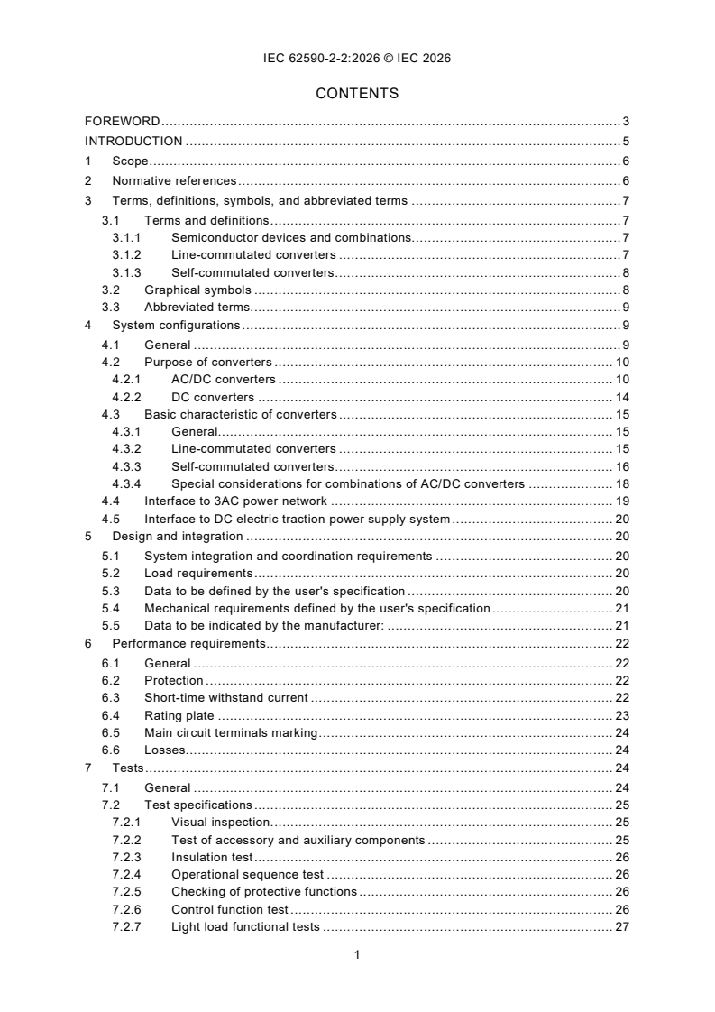
CONTENTS
FOREWORD . 3
INTRODUCTION . 5
1 Scope . 6
2 Normative references . 6
3 Terms, definitions, symbols, and abbreviated terms . 7
3.1 Terms and definitions . 7
3.1.1 Semiconductor devices and combinations. 7
3.1.2 Line-commutated converters . 7
3.1.3 Self-commutated converters . 8
3.2 Graphical symbols . 8
3.3 Abbreviated terms. 9
4 System configurations . 9
4.1 General . 9
4.2 Purpose of converters . 10
4.2.1 AC/DC converters . 10
4.2.2 DC converters . 14
4.3 Basic characteristic of converters . 15
4.3.1 General. 15
4.3.2 Line-commutated converters . 15
4.3.3 Self-commutated converters . 16
4.3.4 Special considerations for combinations of AC/DC converters . 18
4.4 Interface to 3AC power network . 19
4.5 Interface to DC electric traction power supply system . 20
5 Design and integration . 20
5.1 System integration and coordination requirements . 20
5.2 Load requirements . 20
5.3 Data to be defined by the user's specification . 20
5.4 Mechanical requirements defined by the user's specification . 21
5.5 Data to be indicated by the manufacturer: . 21
6 Performance requirements . 22
6.1 General . 22
6.2 Protection . 22
6.3 Short-time withstand current . 22
6.4 Rating plate . 23
6.5 Main circuit terminals marking . 24
6.6 Losses. 24
7 Tests . 24
7.1 General . 24
7.2 Test specifications . 25
7.2.1 Visual inspection . 25
7.2.2 Test of accessory and auxiliary components . 25
7.2.3 Insulation test . 26
7.2.4 Operational sequence test . 26
7.2.5 Checking of protective functions . 26
7.2.6 Control function test . 26
7.2.7 Light load functional tests . 27
7.2.8 Load test . 27
7.2.9 Inherent voltage drop . 27
7.2.10 Temperature rise test . 27
7.2.11 Short-time withstand current test . 28
7.2.12 Power loss determination . 29
7.2.13 Audible sound. 29
7.2.14 EMC . 29
7.2.15 Harmonic measurements . 30
7.2.16 Power factor measurement . 30
7.2.17 Mechanical tests . 30
Annex A (informative) Power flow control strategies . 31
A.1 General . 31
A.2 Examples for DC side coordination of current versus voltage characteristics . 31
Annex B (informative) Calculation factors . 42
Annex C (informative) Test circuits for load tests . 43
C.1 General . 43
C.2 Test circuits . 43
Bibliography . 45
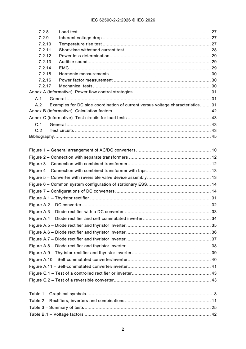
Figure 1 – General arrangement of AC/DC converters . 10
Figure 2 – Connection with separate transformers . 12
Figure 3 – Connection with combined transformer . 12
Figure 4 – Connection with combined transformer with taps . 13
Figure 5 – Converter with reversible valve device assembly . 13
Figure 6 – Common system configuration of stationary ESS . 14
Figure 7 – Configurations of DC converters . 14
Figure A.1 – Thyristor rectifier . 31
Figure A.2 – DC converter . 32
Figure A.3 – Diode rectifier with a DC converter . 33
Figure A.4 – Diode rectifier and self-commutated inverter . 34
Figure A.5 – Diode rectifier and thyristor inverter . 35
Figure A.6 – Diode rectifier and thyristor inverter . 36
Figure A.7 – Diode rectifier and thyristor inverter . 37
Figure A.8 – Diode rectifier and thyristor inverter . 38
Figure A.9 – Thyristor rectifier and thyristor inverter . 39
Figure A.10 – Self-commutated converter/inverter . 40
Figure A.11 – Self-commutated converter/inverter . 41
Figure C.1 – Test of a controlled rectifier or inverter . 43
Figure C.2 – Test of a reversible converter . 43
Table 1 – Graphical symbols. 8
Table 2 – Rectifiers, inverters and combinations . 11
Table 3 – Summary of tests . 25
Table B.1 – Voltage factors . 42
INTERNATIONAL ELECTROTECHNICAL COMMISSION
____________
Railway applications -
Electronic power converters for fixed installations -
Part 2-2: DC Traction applications - Controlled converters
FOREWORD
1) The International Electrotechnical Commission (IEC) is a worldwide organization for standardization comprising
all national electrotechnical committees (IEC National Committees). The object of IEC is to promote international
co-operation on all questions concerning standardization in the electrical and electronic fields. To this end and
in addition to other activities, IEC publishes International Standards, Technical Specifications, Technical Reports,
Publicly Available Specifications (PAS) and Guides (hereafter referred to as “IEC Publication(s)”). Their
preparation is entrusted to technical committees; any IEC National Committee interested in the subject dealt with
may participate in this preparatory work. International, governmental and non-governmental organizations liaising
with the IEC also participate in this preparation. IEC collaborates closely with the International Organization for
Standardization (ISO) in accordance with conditions determined by agreement between the two organizations.
2) The formal decisions or agreements of IEC on technical matters express, as nearly as possible, an international
consensus of opinion on the relevant subjects since each technical committee has representation from all
interested IEC National Committees.
3) IEC Publications have the form of recommendations for international use and are accepted by IEC National
Committees in that sense. While all reasonable efforts are made to ensure that the technical content of IEC
Publications is accurate, IEC cannot be held responsible for the way in which they are used or for any
misinterpretation by any end user.
4) In order to promote international uniformity, IEC National Committees undertake to apply IEC Publications
transparently to the maximum extent possible in their national and regional publications. Any divergence between
any IEC Publication and the corresponding national or regional publication shall be clearly indicated in the latter.
5) IEC itself does not provide any attestation of conformity. Independent certification bodies provide conformity
assessment services and, in some areas, access to IEC marks of conformity. IEC is not responsible for any
services carried out by independent certification bodies.
6) All users should ensure that they have the latest edition of this publication.
7) No liability shall attach to IEC or its directors, employees, servants or agents including individual experts and
members of its technical committees and IEC National Committees for any personal injury, property damage or
other damage of any nature whatsoever, whether direct or indirect, or for costs (including legal fees) and
expenses arising out of the publication, use of, or reliance upon, this IEC Publication or any other IEC
Publications.
8) Attention is drawn to the Normative references cited in this publication. Use of the referenced publications is
indispensable for the correct application of this publication.
9) IEC draws attention to the possibility that the implementation of this document may involve the use of (a)
patent(s). IEC takes no position concerning the evidence, validity or applicability of any claimed patent rights in
respect thereof. As of the date of publication of this document, IEC had not received notice of (a) patent(s), which
may be required to implement this document. However, implementers are cautioned that this may not represent
the latest information, which may be obtained from the patent database available at https://patents.iec.ch. IEC
shall not be held responsible for identifying any or all such patent rights.
IEC 62590-2-2 has been prepared by IEC technical committee 9: Electrical equipment and
systems for railways. It is an International Standard.
This first edition partially cancels and replaces IEC 62589 and IEC 62590. This edition
constitutes a technical revision.
The text of this International Standard is based on the following documents:
Draft Report on voting
9/3312/FDIS 9/3328/RVD
Full information on the voting for its approval can be found in the report on voting indicated in
the above table.
The language used for the development of this International Standard is English.
This document was drafted in accordance with ISO/IEC Directives, Part 2, and developed in
accordance with ISO/IEC Directives, Part 1 and ISO/IEC Directives, IEC Supplement, available
at www.iec.ch/members_experts/refdocs. The main document types developed by IEC are
described in greater detail at www.iec.ch/publications.
A list of all parts in the IEC 62590 series, published under the general title Railway applications -
Electronic power converters for fixed installations, can be found on the IEC website.
The committee has decided that the contents of this document will remain unchanged until the
stability date indicated on the IEC website under webstore.iec.ch in the data related to the
specific document. At this date, the document will be
– reconfirmed,
– withdrawn, or
– revised.
INTRODUCTION
Semiconductor converters for traction power supply differ from other electronic power
converters for industrial use due to special electrical service conditions and due to the large
range of load variation and the particular characteristics of the load.
Controlled rectifiers supply a DC traction network from a three-phase power network using
controllable semiconductor valves. Inverters allow the recuperation of power from a DC traction
network into a three-phase power network. Reversible converters combine the functions of a
rectifier and an inverter.
DC converters are self-commutated converters for connecting the DC traction network to other
DC networks or storage devices.
1 Scope
This part of IEC 62590 describes functions and working principles, specifies requirements,
interfaces, and test methods for controlled converters for DC electric traction power supply
systems:
– AC/DC converters:
• rectifiers,
• inverters,
• combinations.
– DC converters.
The purpose of the converters can be a power connection to other power networks or energy
storages.
The common characteristic of this equipment is the possibility to influence the power flow in the
DC electric traction power supply system. The converters can be:
– line-commutated;
– self-commutated.
This document applies to fixed installations of the following electric traction systems:
– railway networks,
– metropolitan transport networks including metros, tramways, trolleybuses and fully
automated transport systems, magnetic levitated transport systems, and electric road
systems.
2 Normative references
The following documents are referred to in the text in such a way that some or all of their content
constitutes requirements of this document. For dated references, only the edition cited applies.
For undated references, the latest edition of the referenced document (including any
amendments) applies.
IEC 60071-1, Insulation co-ordination - Part 1: Definitions, principles and rules
IEC 60529, Degrees of protection provided by enclosures (IP code)
IEC 62590-1:2025, Railway applications - Electronic power converters for fixed installations -
Part 1: General requirements
IEC 62695, Railway applications - Fixed installations - Traction transformers
IEC 62236-5, Railway applications - Electromagnetic compatibility - Part 5: Emission and
immunity of fixed power supply installations and apparatus
3 Terms, definitions, symbols, and abbreviated terms
For the purposes of this document, the terms and definitions given in IEC 62590-1 and the
following apply.
ISO and IEC maintain terminology databases for use in standardization at the following
addresses:
– IEC Electropedia: available at https://www.electropedia.org/
– ISO Online browsing platform: available at https://www.iso.org/obp
3.1 Terms and definitions
3.1.1 Semiconductor devices and combinations
3.1.1.1
rated current
I
Nd
value of a DC current a controlled converter is designed for, referring
to the DC electric traction power supply system
Note 1 to entry: All rated values of the components are derived from this value.
Note 2 to entry: A converter can have a rated continuous current and rated currents in conjunction with a duty class.
3.1.1.2
rated DC power
rated current multiplied with nominal DC voltage
Note 1 to entry: This value refers to DC electric traction power supply system side.
3.1.1.3
reversible converter
converter in which the direction of the power flow is reversible
[SOURCE IEC 60050-551:1998, 551-12-37, modified – Figure 1 has been omitted.]
3.1.2 Line-commutated converters
3.1.2.1
trigger delay angle
time expressed in angular measure by which the trigger pulse is delayed with respect to the
reference instant in the case of phase control
Note 1 to entry: With line, machine or load commutated converters the reference instant is the zero crossing instant
of the commutating voltage. With AC controllers it is the zero crossing instant of the supply voltage. For AC controllers
with inductive loads the trigger delay angle is the sum of the phase shift and the current delay angle.
[SOURCE: IEC 60050-551:1998, 551-16-33, modified – In the definition, “the” has been
deleted.]
3.1.2.2
commutation failure
failure to commutate the current from a conducting arm to the succeeding arm
[SOURCE: IEC 60050-551:1998, 551-16-59, modified – In the definition, “a” has been deleted]
3.1.3 Self-commutated converters
3.1.3.1
switched valve device
controllable valve device which can be turned on and off by a control signal
[SOURCE: IEC 60050-551:1998, 551-14-08, modified – In the definition, “a” has been deleted,
"may" has been replaced with "can".]
3.1.3.2
free-wheeling diode
diode parallel to a switched valve device in reverse direction fulfilling the purpose of a free-
wheeling arm
3.1.3.3
buck converter
direct DC converter providing an output voltage which is lower than the input voltage
[SOURCE: IEC 60050-551:1998, 551-12-33]
3.2 Graphical symbols
Table 1 lists all symbols used in this document. These symbols are based on symbols registered
in IEC 60617.
Table 1 – Graphical symbols
Symbol Explanation
AC/DC converter with optional indication of power
flow direction
SOURCE: IEC 60617-S00213:2001-07;
3~ 3~ 3~
IEC 60617-S01402:2001-09;
IEC 60617-S01403:2001-09
DC DC DC
IEC 60617-S00099:2001-07;
IEC 60617-S00100:2001-07;
IEC 60617-S01407:2001-10.
DC converter
DC
SOURCE: IEC 60617-S00213:2001-07;
DC
IEC 60617-S01402:2001-09.
DC converter with isolation between 2 electrical
circuits
DC
SOURCE: IEC 60617-S00213:2001-07;
DC
IEC 60617-S01402:2001-09;
IEC 60617-S01407:2001-10
diode rectifier (valve device) assembly
SOURCE: IEC 60617-S00641:2001-07;
Rec
Symbol Explanation
IGBT converter (valve device) assembly
SOURCE: IEC 60617-S00616:2001-07;
IEC 60617 S00621:2001-07;
IEC 60617-S00624:2001-07;
IEC 60617-S00641:2001-07.
thyristor converter (valve device) assembly
SOURCE: IEC 60617-S00654:2001-07.
Rec
Transformer with two windings
SOURCE: IEC 60617-S00841:2001-07.
Transformer with three windings
SOURCE: IEC 60617-S00844:2001-07.
Group of connections
SOURCE: IEC 60617-S00002:2001-07.
3.3 Abbreviated terms
3AC three phase alternating current
AC alternating current
ACTB apparatus for connecting the ESU to the DC bus
DC direct current
ESS energy storage system
ESU energy storage unit
IGBT insulated gate bipolar transistor
U power frequency test voltage for power frequency withstand voltage test
a
U nominal DC voltage
dN
U no load transformer voltage, valve side
v0
4 System configurations
4.1 General
The main purpose of controlled electronic power converters for DC electric traction power
supply systems is to establish an intended power flow. The power can flow from a 3AC power
network to the DC electric traction system or vice versa. This can also be a bidirectional power
flow to energy storages or other equipment using regenerated power.
4.2 Purpose of converters
4.2.1 AC/DC converters
4.2.1.1 General
The AC/DC converters connect a 3AC power network with a DC electric traction power supply
system as shown in Figure 1. Requirements from both networks shall be applied, see 5.3.
Figure 1 – General arrangement of AC/DC converters
4.2.1.2 Rectifiers
The purpose of rectifiers is to have a power flow from the 3AC power network to the DC electric
traction power supply system.
Controlled rectifiers operate on an adjustable characteristic curve in the current versus voltage
plane. This characteristic can be adjustable. Examples are given in Annex A. Limits can be
included.
Controlled rectifiers can be line-commutated or self-commutated.
A suitable duty class should be chosen from IEC 62590-1:2025, 5.7.2.
4.2.1.3 Inverters
The purpose of inverters is to enable a power flow from the DC electric traction power supply
system to the 3AC power network to improve the energy efficiency of the railway system.
Inverters operate on an adjustable characteristic curve in the current versus voltage plane. This
characteristic can be adjustable. Examples are given in Annex A. Limits can be included.
Inverters can be line-commutated or self-commutated.
The definition of a load cycle is appropriate in most cases, see IEC 62590-1:2025, 5.7.3.
4.2.1.4 Reversible converters
The purpose of the combination of a rectifier and an inverter is to enable a bidirectional power
exchange between a 3AC power network and the DC electric traction power supply system.
Reversible converters operate on an adjustable characteristic curve in the current versus
voltage plane. This characteristic can be adjustable. Examples are given in Annex A. Limits can
be included.
There is a broad variety of combinations using line-commutated and self-commutated
converters, see Table 2.
Figure 2 to Figure 5 show various possible combinations of rectifiers and inverters that can be
installed in a reversible substation. They can share the same transformer, the same control, or
the same filter.
Commonly used parts of the reversible converter are subject to a combined load requirement.
For the rectifier part a suitable duty class should be chosen. For the inverter part a suitable
load cycle or a suitable duty class should be chosen according to the application, see Figure 2
to Figure 5. This can result in an asymmetric load for 3 winding transformers in special cases
shown in Figure 3 and Figure 4.
IEC 62590-2-1 applies to the uncontrolled part of the reversible converter, if any, and this
document applies to the inverter part.
Table 2 – Rectifiers, inverters and combinations
Rectifier Inverter Reversible converter
3~ 3~ 3~
General symbol
DC DC DC
Inv
Rec
Rec Inv
Examples of associated
Rec
Inv
transformer and valve device
assembly
Rec Inv
Rec Inv
Rec
Inv
Rec/Inv
NOTE 1 The symbols represent typical valve devices used in the respective application.
NOTE 2 "Rec" indicates the use of a rectifier and "Inv" the use of an inverter.
Figure 2 – Connection with separate transformers
A reversible converter configuration can consist of a separated rectifier and inverter. Figure 2
shows such a configuration. Both can be connected to the same 3AC power network or to
different 3AC power networks. The function and design are as independent as possible.
NOTE Dashed symbols represent optional components to achieve symmetry.
Figure 3 – Connection with combined transformer
A reversible converter configuration can share the same main transformer. Such a configuration
is shown in Figure 3. In this case an additional transformer is used to adapt the inverter 3AC
voltage to the rectifier 3AC voltage. If a three-winding transformer with two traction side
windings is used, a single inverter or multiple inverters can be connected to one or both
windings equally. The main transformer shall be designed for both power flow directions.
NOTE Dashed symbols represent optional components to achieve symmetry.
Figure 4 – Connection with combined transformer with taps
Figure 4 shows a configuration with a combined transformer with taps. No additional
transformer is used for the adaptation of the inverter and rectifier voltage.
Figure 5 – Converter with reversible valve device assembly
Figure 5 shows the configuration of a reversible converter using a unique all-in-one reversible
valve device assembly associated with a unique transformer. In this case, the control for both
flow directions is integrated.
More than one traction side transformer winding can be used.
4.2.1.5 Reversible AC/DC converters for energy storages
The purpose of a reversible converter for an energy storage is to connect the DC electric traction
power supply system to an energy storage unit. In this case the ESU is a rotating machine.
IEC 62924 covers reversible converters for energy storage. The converter fulfils the function of
the ACTB.
The configuration is shown in Figure 6.
Load requirements are defined in IEC 62924.
NOTE DC bus means the DC traction power supply system in the addressed use case.
Figure 6 – Common system configuration of stationary ESS
4.2.2 DC converters
A DC converter connects the DC electric traction power supply system to another DC system.
This can be for example a capacitor or battery for energy storage purposes or a DC distribution
system. DC converters can also be used for controlling a wayside braking resistor for consuming
power of braking rolling stock.
NOTE A controlled wayside braking resistor is often called an automatic assured receptivity unit, or a braking
resistor unit.
Figure 7 shows the basic configuration of DC converters.
Figure 7 – Configurations of DC converters
Both sides of a non-isolating DC converter are part of the DC electric traction power supply
system.
An isolating DC converter separates the DC electric traction power supply system from another
system with different insulation coordination.
IEC 62924 covers energy storage. The converter is fulfilling the function of an ACTB.
See Figure 6.
For energy storage purpose load requirements are defined in IEC 62924.
For any other purpose a load class should be selected.
4.3 Basic characteristic of converters
4.3.1 General
Controlled converters have different basic working principles. A coordination between the
transformer and the valve device assembly is required. In most cases the transformer is part of
a filter circuit. The choice of the transformer main values has a major influence on the power
quality of the connected networks.
All controlled converters use voltage and current sensors. Their signals are processed and used
to create firing signals for the semiconductors. For all converters connected to a 3AC power
network, a synchronization with this network is necessary.
The user shall specify the complete operating range, together with the tolerance of the 3AC
network voltage. This information shall be used by the manufacturer to design the transformer
and the valve device assembly.
4.3.2 Line-commutated converters
4.3.2.1 General
The basic behaviour of line-commutated converters is broadly described in IEC 60146-1-1.
An application guide is IEC/TR 60146-1-2.
For basic connections, 6-pulse bridges or combinations thereof are used. The most common
types of line-commutated converters are those with 12-pulse connections. The basic
connections and calculation factors for uncontrolled operation can be taken from
IEC 62590-2-1:2025, Table 1.
NOTE The ratio between the direct voltage drop and the impedance voltage specified in IEC 60146-1-1:2024,
Table 10 have a slightly different meaning.
The DC voltage can be controlled by varying the trigger delay angle. A voltage versus current
characteristic can be established.
4.3.2.2 Line-commutated rectifiers
The transformer’s no-load voltage shall be chosen according to the required range of operation.
The transformer’s no-load voltage for a controlled rectifier is higher than for an uncontrolled
diode rectifier. The trigger delay angle reduces the DC voltage as described in
IEC TR 60146-1-2.
NOTE For the purposes of the rectifier, the trigger delay angle is in the range clearly below 90°. The trigger delay
angle depends on the point of operation and is usually between 60° and 5°. For practical reasons, a trigger delay
angle of 0° is not achievable as thyristors can only be switched on with a forward voltage.
The no-load transformer voltage is higher than the one for a comparable diode rectifier. With a
higher no-load voltage:
– the control range increases;
– the reactive power at the 3AC side increases;
– the DC harmonic content increases;
– the transformer power for the same traction load is higher;
– the 3AC harmonic content is higher at low current.
4.3.2.3 Line-commutated inverters
The transformer’s no-load voltage shall be chosen according to the required range of operation.
NOTE For inverters the trigger delay angle is higher than 90° and the cathodes are connected to the negative
polarity of the supply voltage. A practical range is between 130° and 165° including some reserve.
The expected worst-case operational situation should not lead to a commutation failure. This
worst case consists of the maximum operational DC voltage at the maximum DC current in
combination with the minimum expected operational 3AC power network voltage.
A commutation failure is a short-circuit and leads to an interruption of the inverter operation.
Only intended protection devices shall operate.
A commutation failure shall not lead to any damage of the inverter by design. Only the foreseen
protection devices should be reset. Neighbouring rectifiers should not be affected to guarantee
the availability of the power supply function.
The maximum allowable trigger delay angle depends on:
– the recovery time of the thyristor;
– the overlap angle as a function of the current;
– the commutation inductance provided by the transformer and the short-circuit impedance;
– the 3AC power network voltage;
– the transformer's rated no-load voltage;
– the DC operating voltage.
The choice of a proper traction side no-load voltage for the transformer is important for the
overall behaviour of the inverter. With a higher no-load voltage:
– the probability of a commutation failure decreases;
– the DC harmonic content is higher;
– the reactive power increases;
– the transformer power for the same current is higher.
In most cases a DC side inductor should be used to improve the operational behaviour in case
of a commutation failure and to reduce the DC harmonic current.
4.3.3 Self-commutated converters
4.3.3.1 General
Self-commutated converters are described in IEC 60146-2.
Self-commutated converters are characterized using switched valve devices that can be
switched on and off. The most commonly used valves are transistors and turn-off thyristors,
both with an antiparallel free-wheeling diode.
Self-commutated converters contain a major capacitor smoothing the DC side voltage. Together
with other components, they form a filter. Converters can be pre-charged in order to avoid
current surges.
4.3.3.2 AC/DC converters
A broad variety of connections are used in AC/DC converters.
The common main characteristics of self-commutated AC/DC converters are as follows.
– Use of free-wheeling diodes. The free-wheeling diodes are forming an uncontrolled rectifier.
The DC voltage is higher than the amplitude of the 3AC transformer traction side voltage.
– There is no fixed ratio between the 3AC transformer traction side voltage and the DC
voltage. The ratio is determined by pulse patterns and modulation methods. Safety margins
are used for the adaption to all points of operation.
– The converters can be operated in both directions even if not intended in some applications.
– The transformer is used for voltage adaption and electric isolation of the two networks
– The impedance of the transformer is used for power flow control and is part of a filter.
– Harmonic orders are specific for every converter type, on the DC side as well as on the
AC side.
– A major capacitance on the DC side is required for operation.
Pulse frequency, modulation method and number of parallel units define the harmonic orders
on the 3AC power network side as well as on the DC side. Coordination is recommended to
avoid frequencies used by the signalling system as well as resonance frequencies as far as
they are identified.
A self-commutated AC/DC converter can have additional control functions such as providing
reactive power for the 3AC power network side or active filtering. These optional functions shall
be specified if requested by the user.
4.3.3.3 DC converters
DC converters are mostly self-commutated.
DC converters are mostly reversible.
DC converters use a filter on the DC traction side.
Applications for energy storages shall be bidirectional. The free-wheeling diodes may carry a
current in the case of a DC electric traction power supply system short-circuit. A disconnection
device can be used for this case.
The power flow is controlled in both directions or in one direction only for wayside resistors.
For non-isolated DC converters boost or buck converters can be used.
Isolating DC converters consist of an inverter, a transformer, and a rectifier. They can be used
to connect the DC electric traction power supply system to other DC power systems. Both DC
circuits can have a different insulation level. In the terminology of power electronics, this type
is an indirect DC converter with an AC intermediate circuit.
Both sides of a non-isolating DC converter are part of the DC electric traction power supply
system.
4.3.4 Special considerations for combinations of AC/DC converters
4.3.4.1 General
The rectifier and inverter functions can be combined in different ways. Both functions can share
components.
Two separate converter units do not share any component. They can be individually designed,
delivered, and operated. They can be connected to different 3AC power networks.
A reversible converter is associated with a unique transformer. Power flow requirements for
both directions shall be considered.
All combinations of converters shall be coordinated for proper operation. The current versus
voltage characteristic shall be coordinated in such a way that only intended circulating current
is flowing. Coordination can mean the exchange of information between combined units.
Examples are shown in Annex A and for the circulating current specifically Figure A.6 to
Figure A.8.
Different types of converters require different 3AC transformer traction side voltages at the
valve device assembly for the same DC voltage, see Annex B. This leads to adapting the
voltage either by transformers or DC converters.
4.3.4.2 Diode rectifier combined with thyristor inverter
The voltage versus current characteristic of the rectifier is fixed. The characteristic of the
inverter can be adjusted.
Even if the average inverter voltage is higher than the average rectifier voltage, a circulating
current will occur due to the instantaneous voltages. The circulating current is limited by the
inverter inductor and the transformer impedances.
Both valve device assemblies require different transformer's no-load voltages.
4.3.4.3 Diode rectifier combined with self-commutated inverter
The voltage versus current characteristic of the rectifier is fixed. The characteristic of the
inverter can be adjusted.
The smoothed DC voltage allows for avoiding circulating current.
Both valve device assemblies need different no-load voltages.
4.3.4.4 Thyristor rectifier combined with thyristor inverter
The voltage versus current characteristic for both directions is adjustable.
Circulating current can be avoided if only one converter is active. If both current directions are
active at the same time, high overcurrent can be expected. Changing the current flow direction
is operated after load current has reached zero.
Both directions can use the same transformer traction side voltage without any adaption. In this
case compromises concerning the reactive power are made.
In order to keep the inductive reactive power for the rectifier low, it can be useful to have
different transformer no-load voltages for the rectifier and inverter.
4.3.4.5 Thyristor rectifier combined with self-commutated inverter
The voltage versus current characteristic for both directions is adjustable.
Circulating current can be avoided if only one direction is active.
Both valve device assemblies need different transformer no-load voltages.
4.3.4.6 Self-commutated reversible converter
The voltage versus current characteristic for both directions is adjustable.
Circulating currents are avoided by the working principle.
Additional functions for the power flow on the 3AC power network like reactive power
compensation and active harmonic filtering are possible.
4.4 Interface to 3AC power network
The harmonic behaviour of line-commutated converters is well known and described in
IEC/TR 60146-1-2. Asymmetric and non-sinusoidal conditions of the feeding 3AC power
network are not described.
Self-commutated converters have a less determined harmonic behaviour. The harmonic
behaviour depends on the used connection, modulation method, pulse frequency, filter
equipment and load point.
Every 3AC power network has specific resonance frequencies. If they are excited by the
harmonics of a converter, major disturbances can appear. Specific resonance frequencies to
be avoided shall be made available to the manufacturer to determine countermeasures like
modification of the pulse patterns or use of a filter.
Calculations and simulations can support a more comprehensive description of the harmonic
interface.
The power factor of line-commutated converters i
...
IEC 62590-2-2 ®
Édition 1.0 2026-06
NORME
INTERNATIONALE
Applications ferroviaires - Convertisseurs électroniques de puissance pour
installations fixes -
Partie 2-2: Applications de traction en courant continu - Convertisseurs
commandés
ICS 29.280 ISBN 978-2-8327-1558-1
Droits de reproduction réservés. Sauf indication contraire, aucune partie de cette publication ne peut être reproduite ni
utilisée sous quelque forme que ce soit et par aucun procédé, électronique ou mécanique, y compris la photocopie et
les microfilms, sans l'accord écrit de l'IEC ou du Comité national de l'IEC du pays du demandeur. Si vous avez des
questions sur le copyright de l'IEC ou si vous désirez obtenir des droits supplémentaires sur cette publication, utilisez
les coordonnées ci-après ou contactez le Comité national de l'IEC de votre pays de résidence.
IEC Secretariat Tel.: +41 22 919 02 11
3, rue de Varembé info@iec.ch
CH-1211 Geneva 20 www.iec.ch
Switzerland
A propos de l'IEC
La Commission Electrotechnique Internationale (IEC) est la première organisation mondiale qui élabore et publie des
Normes internationales pour tout ce qui a trait à l'électricité, à l'électronique et aux technologies apparentées.
A propos des publications IEC
Le contenu technique des publications IEC est constamment revu. Veuillez vous assurer que vous possédez l’édition la
plus récente, un corrigendum ou amendement peut avoir été publié.
Recherche de publications IEC - IEC Products & Services Portal - products.iec.ch
webstore.iec.ch/advsearchform Découvrez notre puissant moteur de recherche et consultez
La recherche avancée permet de trouver des publications gratuitement tous les aperçus des publications, symboles
IEC en utilisant différents critères (numéro de référence, graphiques et le glossaire. Avec un abonnement, vous aurez
texte, comité d’études, …). Elle donne aussi des toujours accès à un contenu à jour adapté à vos besoins.
informations sur les projets et les publications remplacées
ou retirées. Electropedia - www.electropedia.org
Le premier dictionnaire d'électrotechnologie en ligne au
IEC Just Published - webstore.iec.ch/justpublished monde, avec plus de 22 500 articles terminologiques en
Restez informé sur les nouvelles publications IEC. Just anglais et en français, ainsi que les termes équivalents
dans 25 langues additionnelles. Egalement appelé
Published détaille les nouvelles publications parues.
Disponible en ligne et une fois par mois par email. Vocabulaire Electrotechnique International (IEV) en ligne.
Service Clients - webstore.iec.ch/csc
Si vous désirez nous donner des commentaires sur cette
publication ou si vous avez des questions contactez-
nous: sales@iec.ch.
SOMMAIRE
AVANT-PROPOS . 3
INTRODUCTION . 5
1 Domaine d'application . 6
2 Références normatives . 6
3 Termes, définitions, symboles et abréviations . 7
3.1 Termes et définitions . 7
3.1.1 Dispositifs à semiconducteurs et combinaisons . 7
3.1.2 Convertisseurs commutés par le réseau . 7
3.1.3 Convertisseurs autocommutés . 8
3.2 Pictogrammes . 8
3.3 Abréviations . 9
4 Configurations du système . 10
4.1 Généralités . 10
4.2 Objectif des convertisseurs . 10
4.2.1 Convertisseurs alternatif/continu . 10
4.2.2 Convertisseurs à courant continu . 15
4.3 Caractéristique de base des convertisseurs . 15
4.3.1 Généralités . 15
4.3.2 Convertisseurs commutés par le réseau . 16
4.3.3 Convertisseurs autocommutés . 17
4.3.4 Considérations particulières pour les combinaisons de convertisseurs
alternatif/continu . 19
4.4 Interface avec le réseau de distribution 3AC . 20
4.5 Interface avec le système d'alimentation électrique de traction en courant
continu . 21
5 Conception et intégration . 21
5.1 Exigences relatives à l'intégration et à la coordination du système . 21
5.2 Exigences de charge . 21
5.3 Données à définir dans la spécification utilisateur . 22
5.4 Exigences mécaniques selon la spécification utilisateur . 22
5.5 Données à indiquer par le constructeur : . 23
6 Exigences de performances . 23
6.1 Généralités . 23
6.2 Protection . 23
6.3 Courant de courte durée admissible . 24
6.4 Plaque signalétique . 24
6.5 Marquage des bornes du circuit principal . 25
6.6 Pertes . 25
7 Essais . 25
7.1 Généralités . 25
7.2 Spécifications d'essai. 26
7.2.1 Examen visuel . 26
7.2.2 Essai des composants accessoires et auxiliaires . 27
7.2.3 Essai d'isolement . 27
7.2.4 Essai des séquences en fonctionnement . 27
7.2.5 Vérification des fonctions de protection . 27
7.2.6 Essai des fonctions de commande . 28
7.2.7 Essais de fonctionnement à puissance réduite . 28
7.2.8 Essai en charge . 28
7.2.9 Chute de tension inhérente . 28
7.2.10 Essai d'échauffement . 29
7.2.11 Essai de tenue en courant de courte durée . 29
7.2.12 Détermination des pertes de puissance . 30
7.2.13 Signaux sonores . 31
7.2.14 EMC . 31
7.2.15 Mesurage des harmoniques . 31
7.2.16 Mesurage du facteur de puissance . 32
7.2.17 Essais mécaniques . 32
Annexe A (informative) Stratégies de commande de circulation de la puissance . 33
A.1 Généralités . 33
A.2 Exemples de coordination côté courant continu des caractéristiques
courant/tension . 33
Annexe B (informative) Facteurs de calcul . 44
Annexe C (informative) Circuits d'essai pour les essais de charge . 45
C.1 Généralités . 45
C.2 Circuits d'essai . 45
Bibliographie . 47
Figure 1 – Configuration générale des convertisseurs alternatif/continu . 10
Figure 2 – Connexion à des transformateurs distincts . 12
Figure 3 – Connexion à un transformateur combiné . 13
Figure 4 – Connexion à un transformateur combiné avec prises . 13
Figure 5 – Convertisseur avec ensemble de valves réversible . 14
Figure 6 – Configuration de système courante d'un ESS stationnaire . 14
Figure 7 – Configurations de convertisseurs à courant continu. 15
Figure A.1 – Redresseur à thyristors . 33
Figure A.2 – Convertisseur à courant continu . 34
Figure A.3 – Redresseur à diodes avec un convertisseur à courant continu . 35
Figure A.4 – Redresseur à diodes et onduleur autocommuté . 36
Figure A.5 – Redresseur à diodes et onduleur à thyristors . 37
Figure A.6 – Redresseur à diodes et onduleur à thyristors . 38
Figure A.7 – Redresseur à diodes et onduleur à thyristors . 39
Figure A.8 – Redresseur à diodes et onduleur à thyristors . 40
Figure A.9 – Redresseur à thyristors et onduleur à thyristors . 41
Figure A.10 – Convertisseur/onduleur autocommuté . 42
Figure A.11 – Convertisseur/onduleur autocommuté . 43
Figure C.1 – Essai d'un redresseur ou d'un onduleur commandé . 45
Figure C.2 – Essai d'un convertisseur réversible . 46
Tableau 1 – Pictogrammes . 8
Tableau 2 – Redresseurs, onduleurs et dispositifs combinés . 12
Tableau 3 – Récapitulatif des essais . 26
Tableau B.1 – Facteurs de tension . 44
COMMISSION ÉLECTROTECHNIQUE INTERNATIONALE
____________
Applications ferroviaires -
Convertisseurs électroniques de puissance pour installations fixes -
Partie 2-2: Applications de traction en courant continu -
Convertisseurs commandés
AVANT-PROPOS
1) La Commission Électrotechnique Internationale (IEC) est une organisation mondiale de normalisation composée
de l'ensemble des comités électrotechniques nationaux (Comités nationaux de l'IEC). L'IEC a pour objet de
favoriser la coopération internationale pour toutes les questions de normalisation dans les domaines de
l'électricité et de l'électronique. À cet effet, l'IEC – entre autres activités – publie des Normes internationales,
des Spécifications techniques, des Rapports techniques, des Spécifications accessibles au public (PAS) et des
Guides (ci-après dénommés "Publication(s) de l'IEC"). Leur élaboration est confiée à des comités d'études, aux
travaux desquels tout Comité national intéressé par le sujet traité peut participer. Les organisations
internationales, gouvernementales et non gouvernementales, en liaison avec l'IEC, participent également aux
travaux. L'IEC collabore étroitement avec l'Organisation Internationale de Normalisation (ISO), selon des
conditions fixées par accord entre les deux organisations.
2) Les décisions ou accords officiels de l'IEC concernant les questions techniques représentent, dans la mesure du
possible, un accord international sur les sujets étudiés, étant donné que les Comités nationaux de l'IEC intéressés
sont représentés dans chaque comité d'études.
3) Les Publications de l'IEC se présentent sous la forme de recommandations internationales et sont agréées
comme telles par les Comités nationaux de l'IEC. Tous les efforts raisonnables sont entrepris afin que l'IEC
s'assure de l'exactitude du contenu technique de ses publications; l'IEC ne peut pas être tenue responsable de
l'éventuelle mauvaise utilisation ou interprétation qui en est faite par un quelconque utilisateur final.
4) Dans le but d'encourager l'uniformité internationale, les Comités nationaux de l'IEC s'engagent, dans toute la
mesure possible, à appliquer de façon transparente les Publications de l'IEC dans leurs publications nationales
et régionales. Toutes divergences entre toutes Publications de l'IEC et toutes publications nationales ou
régionales correspondantes doivent être indiquées en termes clairs dans ces dernières.
5) L'IEC elle-même ne fournit aucune attestation de conformité. Des organismes de certification indépendants
fournissent des services d'évaluation de conformité et, dans certains secteurs, accèdent aux marques de
conformité de l'IEC. L'IEC n'est responsable d'aucun des services effectués par les organismes de certification
indépendants.
6) Tous les utilisateurs doivent s'assurer qu'ils sont en possession de la dernière édition de cette publication.
7) Aucune responsabilité ne doit être imputée à l'IEC, à ses administrateurs, employés, auxiliaires ou mandataires,
y compris ses experts particuliers et les membres de ses comités d'études et des Comités nationaux de l'IEC,
pour tout préjudice causé en cas de dommages corporels et matériels, ou de tout autre dommage de quelque
nature que ce soit, directe ou indirecte, ou pour supporter les coûts (y compris les frais de justice) et les dépenses
découlant de la publication ou de l'utilisation de cette Publication de l'IEC ou de toute autre Publication de l'IEC,
ou au crédit qui lui est accordé.
8) L'attention est attirée sur les références normatives citées dans cette publication. L'utilisation de publications
référencées est obligatoire pour une application correcte de la présente publication.
9) L'IEC attire l'attention sur le fait que la mise en application du présent document peut entraîner l'utilisation d'un
ou de plusieurs brevets. L'IEC ne prend pas position quant à la preuve, à la validité et à l'applicabilité de tout
droit de brevet revendiqué à cet égard. À la date de publication du présent document, l'IEC n'avait pas reçu
notification qu'un ou plusieurs brevets pouvaient être nécessaires à sa mise en application. Toutefois, il y a lieu
d'avertir les responsables de la mise en application du présent document que des informations plus récentes
sont susceptibles de figurer dans la base de données de brevets, disponible à l'adresse https://patents.iec.ch.
L'IEC ne saurait être tenue pour responsable de ne pas avoir identifié de tels droits de brevets et de ne pas avoir
signalé leur existence.
L'IEC 62590-2-2 a été établi par le comité d'études 9 de l'IEC: Matériels et systèmes électriques
ferroviaires. Il s'agit d'une Norme internationale.
Cette première édition annule partiellement et remplace l'IEC 62589 et l'IEC 62590. Cette
édition constitue une révision technique.
La présente version bilingue (2026-10) correspond à la version anglaise monolingue publiée en
2026-06.
La version française de cette norme n'a pas été soumise au vote.
La langue utilisée pour l'élaboration de cette Norme internationale est l'anglais.
Cette publication a été rédigée selon les Directives ISO/IEC, Partie 2, et élaborée selon les
Directives ISO/IEC, Partie 1 et les Directives ISO/IEC, Supplément IEC, disponibles à l'adresse
suivante: www.iec.ch/members_experts/refdocs. Les principaux types de documents élaborés
par l'IEC sont décrits plus en détail sur le site internet: www.iec.ch/publications.
Une liste de toutes les parties de la série IEC 62590, publiées sous le titre général Applications
ferroviaires - Convertisseurs électroniques de puissance pour installations fixes, peut être
consultée sur le site web de l'IEC.
Le comité a décidé que le contenu de cette publication ne sera pas modifié avant la date de
stabilité indiquée sur le site web de l'IEC sous webstore.iec.ch dans les données relatives à la
publication recherchée. À cette date, la publication sera
– reconduite,
– supprimée, ou
– révisée.
INTRODUCTION
Les convertisseurs à semiconducteurs d'alimentation de traction diffèrent des autres
convertisseurs électroniques de puissance à usage industriel en raison des conditions
électriques particulières rencontrées en service, des grandes variations de charge et des
caractéristiques particulières de la charge.
Les redresseurs commandés alimentent un réseau de traction en courant continu à partir d'un
réseau de distribution électrique en triphasé au moyen de valves à semiconducteurs
commandables. Des onduleurs permettent de récupérer la puissance d'un réseau de traction
en courant continu pour alimenter un réseau de distribution électrique en triphasé. Les
convertisseurs réversibles combinent les fonctions d'un redresseur et d'un onduleur.
Les convertisseurs à courant continu sont des convertisseurs autocommutés servant à
raccorder le réseau de traction en courant continu à d'autres dispositifs de stockage ou réseaux
en courant continu.
1 Domaine d'application
La présente partie de l'IEC 62590 décrit les fonctions et les principes de fonctionnement,
spécifie les exigences, les interfaces et les méthodes d'essai des convertisseurs commandés
pour les systèmes d'alimentation électrique de traction en courant continu :
– Convertisseurs alternatif/continu :
• redresseurs,
• onduleurs,
• dispositifs combinés.
– Convertisseurs à courant continu.
L'objectif des convertisseurs peut être d'établir une connexion électrique avec d'autres réseaux
ou systèmes de stockage de l'énergie.
Ces équipements ont comme caractéristique commune la possibilité d'influencer la circulation
de la puissance dans le système d'alimentation électrique de traction en courant continu. Les
convertisseurs peuvent être :
– commutés par le réseau;
– autocommutés.
Le présent document s'applique aux installations fixes des systèmes de traction électrique
suivants :
– réseaux ferroviaires,
– réseaux de transport métropolitains, y compris métros, tramways, trolleybus et systèmes de
transport entièrement automatiques, systèmes de transport à sustentation magnétique et
systèmes routiers électriques.
2 Références normatives
Les documents suivants sont cités dans le texte de sorte qu'ils constituent, pour tout ou partie
de leur contenu, des exigences du présent document. Pour les références datées, seule
l'édition citée s'applique. Pour les références non datées, la dernière édition du document de
référence s'applique (y compris les éventuels amendements).
IEC 60071-1, Coordination de l'isolement - Partie 1: Définitions, principes et règles
IEC 60529, Degrés de protection procurés par les enveloppes (code IP)
IEC 62590-1:2025, Applications ferroviaires - Convertisseurs électroniques de puissance pour
installations fixes - Partie 1: Exigences générales
IEC 62695, Applications ferroviaires - Installations fixes - Transformateurs de traction
IEC 62236-5, Applications ferroviaires - Compatibilité électromagnétique - Partie 5: Émission
et immunité des installations fixes d'alimentation de puissance et des équipements associés
3 Termes, définitions, symboles et abréviations
Pour les besoins du présent document, les termes et définitions donnés dans l'IEC 62590-1
ainsi que les suivants s'appliquent.
L'ISO et l'IEC tiennent à jour des bases de données terminologiques destinées à être utilisées
en normalisation, consultables aux adresses suivantes:
– IEC Electropedia: disponible à l'adresse https://www.electropedia.org/
– ISO Online browsing platform: disponible à l'adresse https://www.iso.org/obp
3.1 Termes et définitions
3.1.1 Dispositifs à semiconducteurs et combinaisons
3.1.1.1
courant assigné
I
Nd
valeur d'un courant continu pour laquelle un convertisseur
commandé est conçu, en référence au système d'alimentation électrique de traction en courant
continu
Note 1 à l'article : Toutes les valeurs assignées des composants sont déterminées à partir de cette valeur.
Note 2 à l'article : Un convertisseur peut avoir un courant continu assigné et des courants assignés, associés à une
classe de service.
3.1.1.2
puissance assignée en courant continu
courant assigné multiplié par une tension continue nominale
Note 1 à l'article : Cette valeur s'applique côté système d'alimentation électrique de traction en courant continu.
3.1.1.3
convertisseur réversible
convertisseur dans lequel le sens de circulation de la puissance peut être inversé
[SOURCE: IEC 60050-551:1998, 551-12-37, modifiée – La Figure 1 n'a pas été reprise.]
3.1.2 Convertisseurs commutés par le réseau
3.1.2.1
angle de retard de l'ordre d'amorçage
dans le cas de la commande de phase, durée exprimée en mesure angulaire pendant laquelle
l'impulsion d'amorçage est retardée par rapport à un instant de référence
Note 1 à l'article : Pour les convertisseurs commutés par le réseau, par machine ou par la charge, l'instant de
référence est l'instant de passage par zéro de la tension de commutation. Pour les gradateurs, c'est l'instant de
passage par zéro de la tension d'alimentation. Pour les gradateurs associés à des charges inductives, l'angle de
retard de l'ordre d'amorçage est la somme du déphasage et de l'angle de retard à l'amorçage.
[SOURCE: IEC 60050-551:1998, 551-16-33]
3.1.2.2
raté de commutation
défaillance pour laquelle le courant n'est pas commuté du bras en conduction au bras suivant
[SOURCE: IEC 60050-551:1998, 551-16-59]
3.1.3 Convertisseurs autocommutés
3.1.3.1
valve commutée
valve commandable qui peut être rendue conductrice ou bloquée en lui appliquant un signal de
commande
[SOURCE: IEC 60050-551:1998, 551-14-08]
3.1.3.2
diode de roue libre
diode parallèle à une valve commutée en sens inverse, remplissant les fonctions d'un bras de
roue libre
3.1.3.3
convertisseur abaisseur
convertisseur de courant continu direct délivrant une tension de sortie inférieure à la tension
d'entrée
[SOURCE: IEC 60050-551:1998, 551-12-33]
3.2 Pictogrammes
Le Tableau 1 répertorie l'ensemble des pictogrammes utilisés dans le présent document. Ces
pictogrammes s'appuient sur ceux de l'IEC 60617.
Tableau 1 – Pictogrammes
Pictogramme Explication
Convertisseur alternatif/continu avec indication
facultative du sens de circulation de la puissance
SOURCE: IEC 60617-S00213:2001-07;
IEC 60617-S01402:2001-09;
IEC 60617-S01403:2001-09;
IEC 60617-S00099:2001-07;
IEC 60617-S00100:2001-07;
IEC 60617-S01407:2001-10.
Convertisseur à courant continu
SOURCE: IEC 60617-S00213:2001-07;
IEC 60617-S01402:2001-09.
Convertisseur à courant continu avec isolement
entre 2 circuits électriques
SOURCE: IEC 60617-S00213:2001-07;
IEC 60617-S01402:2001-09;
IEC 60617-S01407:2001-10
Ensemble redresseur à diodes (valve)
SOURCE: IEC 60617-S00641:2001-07;
Pictogramme Explication
Ensemble convertisseur IGBT (valve)
SOURCE: IEC 60617-S00616:2001-07;
IEC 60617 S00621:2001-07;
IEC 60617-S00624:2001-07;
IEC 60617-S00641:2001-07.
Ensemble convertisseur à thyristors (valve)
SOURCE: IEC 60617-S00654:2001-07.
Transformateur à deux enroulements
SOURCE: IEC 60617-S00841:2001-07.
Transformateur à trois enroulements
SOURCE: IEC 60617-S00844:2001-07.
Groupe de connexions
SOURCE: IEC 60617-S00002:2001-07.
3.3 Abréviations
3AC courant alternatif triphasé
ACTB appareillage utilisé pour connecter l'ESU à un bus
en courant continu
CA courant alternatif
CC courant continu
ESS (Energy Storage System) système de stockage de l'énergie
ESU (Energy Storage Unit) unité de stockage de l'énergie
IGBT (Insulated Gate Bipolar Transistor) transistor bipolaire à grille isolée
U tension d'essai à la fréquence industrielle pour
a
l'essai de tension de tenue à la fréquence
industrielle
U tension continue nominale
dN
U tension à vide du transformateur, côté valve
v0
4 Configurations du système
4.1 Généralités
Le principal objectif des convertisseurs électroniques de puissance commandés pour des
systèmes d'alimentation électrique de traction en courant continu est d'établir la circulation de
puissance prévue. La puissance peut circuler d'un réseau de distribution 3AC vers un système
de traction électrique en courant continu ou inversement. Il peut également s'agir d'une
circulation de puissance bidirectionnelle vers des systèmes de stockage de l'énergie ou d'autres
équipements utilisant une puissance régénérée.
4.2 Objectif des convertisseurs
4.2.1 Convertisseurs alternatif/continu
4.2.1.1 Généralités
Les convertisseurs alternatif/continu connectent un réseau de distribution 3AC à un système
d'alimentation électrique de traction en courant continu, comme cela est représenté à la
Figure 1. Les exigences des deux réseaux doivent être appliquées, voir 5.3.
Figure 1 – Configuration générale des convertisseurs alternatif/continu
4.2.1.2 Redresseurs
L'objectif des redresseurs est de faire circuler la puissance entre le réseau de distribution 3AC
et le système d'alimentation électrique de traction en courant continu.
Les redresseurs commandés fonctionnent sur une courbe caractéristique réglable dans le plan
courant/tension. Cette caractéristique peut être réglable. Des exemples sont fournis à
l'Annexe A. Des limites peuvent être prévues.
Les redresseurs commandés peuvent être commutés par le réseau ou autocommutés.
Il convient de choisir une classe de service appropriée dans l'IEC 62590-1:2025, 5.7.2.
4.2.1.3 Onduleurs
L'objectif des onduleurs est de permettre une circulation de la puissance du système
d'alimentation électrique de traction en courant continu vers le réseau de distribution 3AC afin
d'améliorer l'efficacité énergétique du système ferroviaire.
Les onduleurs fonctionnent sur une courbe caractéristique réglable dans le plan
courant/tension. Cette caractéristique peut être réglable. Des exemples sont fournis à
l'Annexe A. Des limites peuvent être prévues.
Les onduleurs peuvent être commutés par le réseau ou autocommutés.
Il est approprié dans la plupart des cas de définir un cycle de charge; voir l'IEC 62590-1:2025,
5.7.3.
4.2.1.4 Convertisseurs réversibles
L'objectif d'un redresseur/onduleur combiné est de permettre un échange de puissance
bidirectionnel entre un réseau de distribution 3AC et le système d'alimentation électrique de
traction en courant continu.
Les convertisseurs réversibles fonctionnent sur une courbe caractéristique réglable dans le
plan courant/tension. Cette caractéristique peut être réglable. Des exemples sont fournis à
l'Annexe A. Des limites peuvent être prévues.
Il existe une grande diversité de combinaisons différentes utilisant à la fois des convertisseurs
commutés par le réseau et des convertisseurs autocommutés; voir le Tableau 2.
Les Figure 2 à Figure 5 représentent les différentes combinaisons de redresseurs et
d'onduleurs destinés à être installés dans une sous-station réversible. Ils peuvent partager le
même transformateur, la même commande ou le même filtre.
Les parties couramment utilisées du convertisseur réversible sont soumises à une exigence de
charge combinée.
Pour la partie redresseur, il convient de choisir une classe de service appropriée. Pour la partie
onduleur, il convient de choisir un cycle de charge approprié ou une classe de service
appropriée, en fonction de l'application; voir de la Figure 2 à la Figure 5. Cela peut produire
une charge asymétrique pour des transformateurs à 3 enroulements dans les cas particuliers
représentés à la Figure 3 et à la Figure 4.
L'IEC 62590-2-1 s'applique à la partie non commandée du convertisseur réversible, le cas
échéant, alors que le présent document s'applique à la partie onduleur.
Tableau 2 – Redresseurs, onduleurs et dispositifs combinés
Redresseur Onduleur Convertisseur réversible
Pictogramme général
Exemples d'association de
transformateur et d'ensemble
de valves
NOTE 1 Les pictogrammes représentent des ensembles de valves types utilisés dans leur application respective.
NOTE 2 « Red. » indique l'utilisation d'un redresseur et « Ond. » l'utilisation d'un onduleur.
Figure 2 – Connexion à des transformateurs distincts
Une configuration de convertisseur réversible peut comprendre un redresseur et un onduleur
distincts. La Figure 2 représente un exemple de cette configuration. Les deux peuvent être
connectés au même réseau de distribution 3AC ou à des réseaux de distribution 3AC différents.
La fonction et la conception sont aussi indépendantes que possible.
NOTE Les éléments en pointillés représentent des composants facultatifs pour la symétrie.
Figure 3 – Connexion à un transformateur combiné
Une configuration de convertisseur réversible peut partager le même transformateur principal.
Ce type de configuration est représenté à la Figure 3. Dans ce cas, un transformateur
supplémentaire est utilisé pour adapter la tension 3AC de l'onduleur à la tension 3AC du
redresseur. Si un transformateur à trois enroulements avec deux enroulements côté traction
est utilisé, un seul onduleur ou plusieurs onduleurs peuvent être connectés à un ou aux deux
enroulements de manière égale. Le transformateur principal doit être conçu pour les deux sens
de circulation de la puissance.
NOTE Les éléments en pointillés représentent des composants facultatifs pour la symétrie.
Figure 4 – Connexion à un transformateur combiné avec prises
La Figure 4 représente une configuration comprenant un transformateur combiné avec prises.
Aucun transformateur supplémentaire n'est utilisé pour l'adaptation des tensions de l'onduleur
et du redresseur.
Figure 5 – Convertisseur avec ensemble de valves réversible
La Figure 5 représente la configuration d'un convertisseur réversible utilisant un seul ensemble
de valves réversible tout-en-un associé à un transformateur unique. La commande des deux
sens de circulation est intégrée dans ce cas.
Plusieurs enroulements de transformateur côté traction peuvent être utilisés.
4.2.1.5 Convertisseurs alternatif/continu réversibles pour les systèmes de stockage
de l'énergie
L'objectif d'un convertisseur réversible pour le stockage de l'énergie est de connecter le
système d'alimentation électrique de traction en courant continu à une unité de stockage de
l'énergie. Dans ce cas, l'unité de stockage de l'énergie est une machine rotative.
Les convertisseurs réversibles pour le stockage de l'énergie sont couverts par l'IEC 62924. Le
convertisseur remplit la fonction de l'ACTB.
La configuration est représentée à la Figure 6.
Les exigences de charge sont définies dans l'IEC 62924.
NOTE Dans le cas d'utilisation en question, le bus CC désigne le système d'alimentation électrique de traction en
courant continu.
Figure 6 – Configuration de système courante d'un ESS stationnaire
4.2.2 Convertisseurs à courant continu
Un convertisseur à courant continu connecte le système d'alimentation électrique de traction
en courant continu à un autre système à courant continu. Il peut s'agir, par exemple, d'un
condensateur ou d'une batterie destinée au stockage d'énergie ou d'un système de distribution
en courant continu. Les convertisseurs à courant continu peuvent également être utilisés pour
commander une résistance de freinage en bordure de voie pour la consommation d'énergie du
matériel roulant en situation de freinage.
NOTE Une résistance de freinage en bordure de voie commandée est également appelée « unité de réceptivité
automatique » ou « unité de résistance de freinage ».
La Figure 7 représente la configuration de base des convertisseurs à courant continu.
Figure 7 – Configurations de convertisseurs à courant continu
Les deux côtés d'un convertisseur à courant continu sans isolement font partie du système
d'alimentation électrique de traction en courant continu.
Un convertisseur à courant continu avec isolement sépare le système d'alimentation électrique
de traction en courant continu d'un autre système avec une coordination d'isolement différente.
Le stockage de l'énergie est couvert par l'IEC 62924. Le convertisseur remplit la fonction d'un
ACTB. Voir Figure 6.
Pour le stockage de l'énergie, les exigences de charge sont définies dans l'IEC 62924.
Pour les autres applications, il convient de choisir une classe de charge.
4.3 Caractéristique de base des convertisseurs
4.3.1 Généralités
Les convertisseurs commandés ont des principes de fonctionnement de base différents. Une
coordination entre le transformateur et l'ensemble de valves est nécessaire. Dans la plupart
des cas, le transformateur fait partie d'un circuit de filtre. Le choix des valeurs principales du
transformateur a une influence majeure sur la qualité de puissance des réseaux connectés.
Tous les convertisseurs commandés utilisent des capteurs de tension et de courant. Leurs
signaux sont traités et utilisés pour créer des signaux de déclenchement pour les
semiconducteurs. Pour tous les convertisseurs connectés à un réseau de distribution 3AC, une
synchronisation avec ledit réseau est nécessaire.
L'utilisateur doit spécifier l'intégralité de la plage de fonctionnement avec la tolérance de la
tension de réseau 3AC. Ces informations doivent être utilisées par le fabricant pour concevoir
le transformateur et l'ensemble de valves.
4.3.2 Convertisseurs commutés par le réseau
4.3.2.1 Généralités
Le comportement élémentaire des convertisseurs commutés par le réseau est décrit dans les
grandes lignes dans l'IEC 60146-1-1.
L'IEC/TR 60146-1-2 est un exemple de guide d'application.
Pour des connexions de base, des ponts hexaphasés ou leurs combinaisons sont utilisés. Les
types de convertisseurs commutés par le réseau les plus courants sont ceux avec des
connexions dodécaphasées. Les connexions de base et les facteurs de calcul pour un
fonctionnement non commandé peuvent être pris du Tableau 1 de l'IEC 62590-2-1:2025.
NOTE Le rapport entre la chute de tension continue et la tension d'impédance dans le Tableau 10 de
l'IEC 60146-1-1:2024 a une signification légèrement différente.
La tension continue peut être commandée en faisant varier l'angle de retard de l'ordre
d'amorçage. Une caractéristique tension/courant peut être établie.
4.3.2.2 Redresseurs commutés par le réseau
La tension à vide du transformateur doit être choisie en fonction de la plage de fonctionnement
exigée. La tension à vide du transformateur est plus élevée pour un redresseur commandé que
pour un redresseur à diodes non commandé. L'angle de retard de l'ordre d'amorçage réduit la
tension continue, comme cela est décrit dans l'IEC TR 60146-1-2.
NOTE Pour un redresseur, l'angle de retard de l'ordre d'amorçage se trouve clairement dans la plage inférieure à
90°. L'angle de retard de l'ordre d'amorçage dépend du point de fonctionnement et se situe généralement entre 60°
et 5°. Pour des raisons pratiques, il n'est pas possible d'obtenir un angle de retard de l'ordre d'amorçage de 0° car
les thyristors ne peuvent être activés que sous une tension directe.
La tension à vide du transformateur est plus élevée que celle observée pour un redresseur à
diodes comparable. Lorsque la tension à vide est plus élevée :
– la plage de commande augmente;
– la puissance réactive côté 3AC augmente;
– la teneur en harmoniques en courant continu augmente;
– la puissance du transformateur est plus élevée pour la même charge de traction;
– la teneur en harmoniques 3AC est plus élevée sous un faible courant.
4.3.2.3 Onduleurs commutés par le réseau
La tension à vide du transformateur doit être choisie en fonction de la plage de fonctionnement
exigée.
NOTE Pour les onduleurs, l'angle de retard de l'ordre d'amorçage est supérieur à 90° et les cathodes sont
connectées à la polarité négative de la tension d'alimentation. Une plage pratique se situe entre 130° et 165°, en
incluant quelques réserves.
Il convient que la situation d'exploitation la plus défavorable attendue n'entraîne aucun raté de
commutation. Ce cas le plus défavorable implique la tension continue d'exploitation maximale
au courant continu maximal, combinée à la tension minimale d'exploitation attendue du réseau
de distribution 3AC.
Un raté de commutation se présente sous la forme d'un court-circuit et conduit à une
interruption du fonctionnement de l'onduleur. Seuls les dispositifs de protection prévus doivent
fonctionner.
Par conception, un raté de commutation ne doit provoquer aucun endommagement de
l'onduleur. Il convient de réarmer uniquement les dispositifs de protection prévus. Il convient
que les redresseurs adjacents n'en subissent aucun effet afin de garantir la disponibilité de la
fonction d'alimentation.
L'angle de retard de l'ordre d'amorçage maximal admissible dépend :
– du temps de récupération du thyristor;
– de l'angle de chevauchement en fonction du courant;
– de l'inductance de commutation fournie par le transformateur et de l'impédance de court-
circuit;
– de la tension du réseau de distribution 3AC;
– de la tension assignée à vide du transformateur;
– de la tension continue de fonctionnement.
Le choix d'une tension à vide côté traction du transformateur appropriée est important pour le
comportement global de l'onduleur. Lorsque la tension à vide est plus élevée :
– la probabilité d'un raté de commutation diminue;
– la teneur en harmoniques en courant continu est plus élevée;
– la puissance réactive augmente;
– la puissance du transformateur est plus élevée pour le même courant.
Dans la plupart des cas, il convient d'utiliser une bobine d'induction côté courant continu afin
d'améliorer le comportement de fonctionnement en cas de raté de commutation et de réduire
les harmoniques de courant continu.
4.3.3 Convertisseurs autocommutés
4.3.3.1 Généralités
Les convertisseurs autocommutés sont décrits dans l'IEC 60146-2.
Les convertisseurs autocommutés se caractérisent par l'utilisation d'ensembles de valves
commutées qui peuvent être activées et désactivées. Les valves les plus courantes sont des
transistors et des thyristors de coupure, tous deux avec une diode de roue libre antiparallèle.
Les convertisseurs autocommutés contiennent un condensateur majeur qui lisse la tension côté
courant continu. Avec les autres composants, il forme un filtre. Une précharge peut être utilisée
pour éviter les surintensités transitoires.
4.3.3.2 Convertisseurs alternatif/continu
Les convertisseurs alternatif/continu utilisent une grande diversité de connexions.
Les principales caractéristiques communes des convertisseurs alternatif/continu autocommutés
sont les suivantes :
– des diodes de roue libre sont utilisées. Les diodes de roue libre forment un redresseur
non commandé. La tension continue est plus élevée que l'amplitude de la tension côté
traction du transformateur 3AC;
– il n'existe aucun rapport fixe entre la tension côté traction du transformateur 3AC et la
tension continue. Le rapport est déterminé par des motifs d'impulsion et par la méthode de
modulation. Des marges de sécurité sont utilisées pour l'adaptation à tous les points de
fonctionnement;
– les convertisseurs peuvent fonctionner dans les deux directions, même s'ils peuvent ne pas
être prévus pour le faire dans certaines applications;
– le transformateur est utilisé pour l'adaptation de la tension et l'isolement électrique des deux
réseaux;
– l'impédance du transformateur est utilisée pour commander la circulation de la puissance
et fait partie du filtre;
– les ordres des harmoniques sont propres à chaque type de convertisseur, aussi bien côté
courant continu que côté courant alternatif;
– une capacité importante est nécessaire côté courant continu pour assurer le
fonctionnement.
La
...