

IEC 61000-4-29:2026
(Main)Electromagnetic compatibility (EMC) - Part 4-29: Testing and measurement techniques - Voltage dips, short interruptions and voltage variations on d.c. input power port immunity tests
General Information
- Abstract
IEC 61000-4-29:2026 defines test methods for immunity to voltage dips, short interruptions and voltage variations at the DC input power port of electrical or electronic equipment. This document is applicable to equipment and systems whose DC input power ports are intended to be connected to low voltage DC networks external to the equipment and systems. The object of this document is to establish a common and reproducible basis for testing electrical and electronic equipment when subjected to voltage dips, short interruptions or voltage variations on DC input power ports.
This document defines:
- the range of test levels;
- the test generator;
- the test set-up;
- the test procedure.
The test described hereinafter applies to electrical and electronic equipment and systems. It also applies to modules or subsystems whenever the equipment under test’s (EUT) rated power is greater than the test generator capacity specified in Clause 6. The ripple at the DC input power port is not included in the scope of this document. It is covered by IEC 61000‑4‑17. This document does not specify the tests to be applied to particular apparatus or systems. Its main aim is to give a general basic reference to IEC product committees. These product committees (or users and manufacturers of equipment) remain responsible for the appropriate choice of the tests and the severity level to be applied to their equipment. This second edition cancels and replaces the first edition published in 2000. This edition constitutes a technical revision.
This edition includes the following significant technical changes with respect to the previous edition:
a) Increase of the output voltage of the test generator to take into account new DC networks voltages;
b) provision of tolerances for the duration of the voltage changes;
c) limitation of the current when applying short interruptions in low impedance condition;
d) general technical clarifications for the specifications of the test generator and their verification;
e) clarifications regarding the loads used to verify the switching characteristics and the peak inrush current drive capability of the test generator;
f) clarifications regarding the evaluation of test results and test reports;
g) description of the DC environment.
- Status
- Published
- Publication Date
- 29-Jul-2026
- Technical Committee
- SC 77A - EMC - Low frequency phenomena
- Drafting Committee
- WG 6 - TC 77/SC 77A/WG 6
- Current Stage
- PPUB - Publication issued
- Start Date
- 30-Jul-2026
- Completion Date
- 04-Sep-2026
Buy Documents
IEC 61000-4-29:2026 - Electromagnetic compatibility (EMC) - Part 4-29: Testing and measurement techniques - Voltage dips, short interruptions and voltage variations on d.c. input power port immunity tests
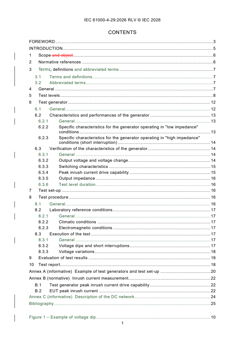
REDLINE IEC 61000-4-29:2026 RLV - Electromagnetic compatibility (EMC) - Part 4-29: Testing and measurement techniques - Voltage dips, short interruptions and voltage variations on d.c. input power port immunity tests
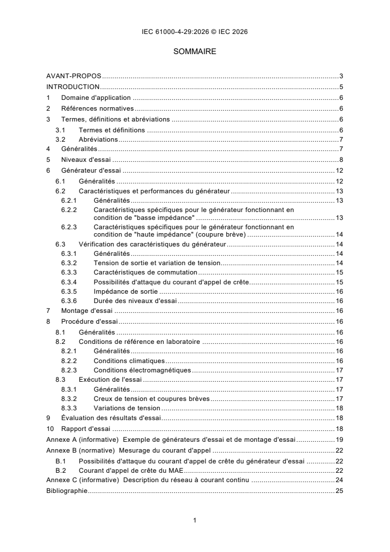
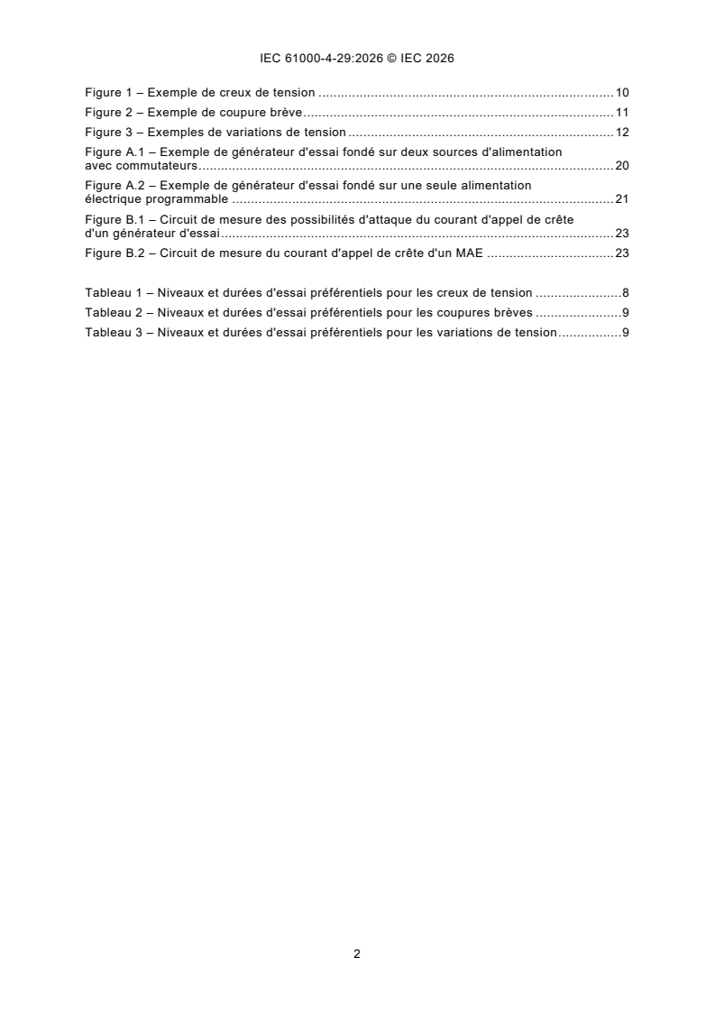
IEC 61000-4-29:2026 - Compatibilité électromagnétique (CEM) - Partie 4-29: Techniques d'essai et de mesure - Creux de tension, coupures breves et variations de tension sur les acces d'alimentation d'entrée en courant continu
Overview
IEC 61000-4-29:2026, published by the International Electrotechnical Commission (IEC), addresses electromagnetic compatibility (EMC) by providing standardized testing and measurement techniques for voltage dips, short interruptions, and voltage variations at DC input power ports of electrical and electronic equipment. This standard is relevant for equipment and systems with DC input power ports intended for connection to low voltage DC networks external to the equipment. Its primary objective is to ensure a reproducible, internationally recognized approach for evaluating immunity when such equipment is subjected to voltage disturbances on DC input power ports.
Key Topics
- Test Levels: Specifies preferred test levels and durations for voltage dips, short interruptions, and voltage variations, facilitating uniform testing across various equipment.
- Test Generator Requirements: Details specifications for test generators, including voltage range, output impedance, and inrush current capabilities for both low and high impedance conditions.
- Test Procedures: Describes a step-by-step process, including test set-up, laboratory reference conditions, and execution for simulating voltage disturbances.
- Evaluation of Results: Guides classification and reporting of immunity test results based on observed loss or degradation of equipment performance.
- Technical Revisions (2026 Edition):
- Enhanced test generator voltage output ranges to accommodate new DC network voltages.
- Defined tolerances for duration of voltage changes.
- Current limitation provisions for short interruptions in low impedance conditions.
- Improved technical clarifications for generator specifications and verification.
- Clarified procedures for evaluating switching characteristics, loads, and inrush currents.
- Expanded descriptions of the low-voltage DC environment.
Applications
IEC 61000-4-29 is widely applicable in sectors that rely on the stable operation of DC-powered equipment, including:
- Industrial Automation: Ensures programmable logic controllers (PLCs), drives, and industrial computers can withstand DC network disturbances.
- Telecommunications: Validates immunity of telecom power systems that frequently operate with low voltage DC inputs.
- Renewable Energy Systems: Assesses the resilience of solar inverters and battery storage modules interfacing with DC grids.
- Transportation: Applies to DC-powered systems such as rail vehicle equipment, where reliable operation under voltage variations is critical.
- Data Centers: Relevant for backup power systems and IT equipment designed to operate on DC supply.
Product committees, equipment manufacturers, and users refer to this standard as a general testing framework. The specific test levels and severity are selected based on application and equipment type to ensure relevant, meaningful EMC immunity assessments.
Related Standards
When considering EMC testing for DC power systems, the following related international standards provide complementary guidance:
- IEC 61000-4-17: Focuses on immunity tests related to ripple at DC input power ports, which is outside the scope of 61000-4-29.
- IEC 61000 Series: Covers a comprehensive range of EMC testing, measurement techniques, limits, and guidelines, providing an integrated approach to EMC compliance.
- IEC 61000-4-11: Addresses voltage dips, short interruptions, and voltage variations for equipment with AC input power ports.
- Product-Specific EMC Standards: Equipment-specific test requirements, chosen by relevant IEC product committees, may reference IEC 61000-4-29 as a basis for immunity testing.
By adhering to IEC 61000-4-29:2026, manufacturers and conformity assessment bodies can demonstrate consistent EMC performance of equipment under real-world DC power disturbance scenarios, supporting global market access and operational reliability.
Relations
- Effective Date
- 05-Sep-2023
Buy Documents
IEC 61000-4-29:2026 - Electromagnetic compatibility (EMC) - Part 4-29: Testing and measurement techniques - Voltage dips, short interruptions and voltage variations on d.c. input power port immunity tests
REDLINE IEC 61000-4-29:2026 RLV - Electromagnetic compatibility (EMC) - Part 4-29: Testing and measurement techniques - Voltage dips, short interruptions and voltage variations on d.c. input power port immunity tests
IEC 61000-4-29:2026 - Compatibilité électromagnétique (CEM) - Partie 4-29: Techniques d'essai et de mesure - Creux de tension, coupures breves et variations de tension sur les acces d'alimentation d'entrée en courant continu
Get Certified
Connect with accredited certification bodies for this standard

ANCE
Mexican certification and testing association.

Intertek Slovenia
Intertek testing, inspection, and certification services in Slovenia.

LNE (Laboratoire National de Métrologie et d'Essais)
French national laboratory for metrology and testing.
Sponsored listings
Frequently Asked Questions
IEC 61000-4-29:2026 is a standard published by the International Electrotechnical Commission (IEC). Its full title is "Electromagnetic compatibility (EMC) - Part 4-29: Testing and measurement techniques - Voltage dips, short interruptions and voltage variations on d.c. input power port immunity tests". This standard covers: IEC 61000-4-29:2026 defines test methods for immunity to voltage dips, short interruptions and voltage variations at the DC input power port of electrical or electronic equipment. This document is applicable to equipment and systems whose DC input power ports are intended to be connected to low voltage DC networks external to the equipment and systems. The object of this document is to establish a common and reproducible basis for testing electrical and electronic equipment when subjected to voltage dips, short interruptions or voltage variations on DC input power ports. This document defines: - the range of test levels; - the test generator; - the test set-up; - the test procedure. The test described hereinafter applies to electrical and electronic equipment and systems. It also applies to modules or subsystems whenever the equipment under test’s (EUT) rated power is greater than the test generator capacity specified in Clause 6. The ripple at the DC input power port is not included in the scope of this document. It is covered by IEC 61000‑4‑17. This document does not specify the tests to be applied to particular apparatus or systems. Its main aim is to give a general basic reference to IEC product committees. These product committees (or users and manufacturers of equipment) remain responsible for the appropriate choice of the tests and the severity level to be applied to their equipment. This second edition cancels and replaces the first edition published in 2000. This edition constitutes a technical revision. This edition includes the following significant technical changes with respect to the previous edition: a) Increase of the output voltage of the test generator to take into account new DC networks voltages; b) provision of tolerances for the duration of the voltage changes; c) limitation of the current when applying short interruptions in low impedance condition; d) general technical clarifications for the specifications of the test generator and their verification; e) clarifications regarding the loads used to verify the switching characteristics and the peak inrush current drive capability of the test generator; f) clarifications regarding the evaluation of test results and test reports; g) description of the DC environment.
IEC 61000-4-29:2026 defines test methods for immunity to voltage dips, short interruptions and voltage variations at the DC input power port of electrical or electronic equipment. This document is applicable to equipment and systems whose DC input power ports are intended to be connected to low voltage DC networks external to the equipment and systems. The object of this document is to establish a common and reproducible basis for testing electrical and electronic equipment when subjected to voltage dips, short interruptions or voltage variations on DC input power ports. This document defines: - the range of test levels; - the test generator; - the test set-up; - the test procedure. The test described hereinafter applies to electrical and electronic equipment and systems. It also applies to modules or subsystems whenever the equipment under test’s (EUT) rated power is greater than the test generator capacity specified in Clause 6. The ripple at the DC input power port is not included in the scope of this document. It is covered by IEC 61000‑4‑17. This document does not specify the tests to be applied to particular apparatus or systems. Its main aim is to give a general basic reference to IEC product committees. These product committees (or users and manufacturers of equipment) remain responsible for the appropriate choice of the tests and the severity level to be applied to their equipment. This second edition cancels and replaces the first edition published in 2000. This edition constitutes a technical revision. This edition includes the following significant technical changes with respect to the previous edition: a) Increase of the output voltage of the test generator to take into account new DC networks voltages; b) provision of tolerances for the duration of the voltage changes; c) limitation of the current when applying short interruptions in low impedance condition; d) general technical clarifications for the specifications of the test generator and their verification; e) clarifications regarding the loads used to verify the switching characteristics and the peak inrush current drive capability of the test generator; f) clarifications regarding the evaluation of test results and test reports; g) description of the DC environment.
IEC 61000-4-29:2026 is classified under the following ICS (International Classification for Standards) categories: 33.100.20 - Immunity. The ICS classification helps identify the subject area and facilitates finding related standards.
IEC 61000-4-29:2026 has the following relationships with other standards: It is inter standard links to IEC 61000-4-29:2000. Understanding these relationships helps ensure you are using the most current and applicable version of the standard.
IEC 61000-4-29:2026 is available in PDF format for immediate download after purchase. The document can be added to your cart and obtained through the secure checkout process. Digital delivery ensures instant access to the complete standard document.
Standards Content (Sample)
IEC 61000-4-29 ®
Edition 2.0 2026-07
INTERNATIONAL
STANDARD
BASIC EMC PUBLICATION
Electromagnetic compatibility (EMC) -
Part 4-29: Testing and measurement techniques - Voltage dips, short
interruptions and voltage variations on d.c. input power port immunity tests
ICS 33.100.20 ISBN 978-2-8327-1415-7
All rights reserved. Unless otherwise specified, no part of this publication may be reproduced or utilized in any form or
by any means, electronic or mechanical, including photocopying and microfilm, without permission in writing from either
IEC or IEC's member National Committee in the country of the requester. If you have any questions about IEC copyright
or have an enquiry about obtaining additional rights to this publication, please contact the address below or your local
IEC member National Committee for further information.
IEC Secretariat Tel.: +41 22 919 02 11
3, rue de Varembé info@iec.ch
CH-1211 Geneva 20 www.iec.ch
Switzerland
About the IEC
The International Electrotechnical Commission (IEC) is the leading global organization that prepares and publishes
International Standards for all electrical, electronic and related technologies.
About IEC publications
The technical content of IEC publications is kept under constant review by the IEC. Please make sure that you have the
latest edition, a corrigendum or an amendment might have been published.
IEC publications search - IEC Products & Services Portal - products.iec.ch
webstore.iec.ch/advsearchform Discover our powerful search engine and read freely all the
The advanced search enables to find IEC publications by a publications previews, graphical symbols and the glossary.
variety of criteria (reference number, text, technical With a subscription you will always have access to up to date
committee, …). It also gives information on projects, content tailored to your needs.
replaced and withdrawn publications.
Electropedia - www.electropedia.org
The world's leading online dictionary on electrotechnology,
IEC Just Published - webstore.iec.ch/justpublished
Stay up to date on all new IEC publications. Just Published containing more than 22 500 terminological entries in English
details all new publications released. Available online and and French, with equivalent terms in 25 additional languages.
once a month by email. Also known as the International Electrotechnical Vocabulary
(IEV) online.
IEC Customer Service Centre - webstore.iec.ch/csc
If you wish to give us your feedback on this publication or
need further assistance, please contact the Customer
Service Centre: sales@iec.ch.
CONTENTS
FOREWORD . 3
INTRODUCTION . 5
1 Scope . 6
2 Normative references . 6
3 Terms, definitions and abbreviated terms . 6
3.1 Terms and definitions. 6
3.2 Abbreviated terms . 7
4 General . 7
5 Test levels . 8
6 Test generator . 12
6.1 General . 12
6.2 Characteristics and performances of the generator . 13
6.2.1 General . 13
6.2.2 Specific characteristics for the generator operating in "low impedance"
conditions . 13
6.2.3 Specific characteristics for the generator operating in "high impedance"
conditions (short interruption) . 14
6.3 Verification of the characteristics of the generator. 14
6.3.1 General . 14
6.3.2 Output voltage and voltage change . 14
6.3.3 Switching characteristics . 15
6.3.4 Peak inrush current drive capability . 15
6.3.5 Output impedance . 16
6.3.6 Test level duration . 16
7 Test set-up . 16
8 Test procedure . 16
8.1 General . 16
8.2 Laboratory reference conditions . 16
8.2.1 General . 16
8.2.2 Climatic conditions . 16
8.2.3 Electromagnetic conditions . 17
8.3 Execution of the test . 17
8.3.1 General . 17
8.3.2 Voltage dips and short interruptions . 17
8.3.3 Voltage variations . 17
9 Evaluation of test results . 18
10 Test report . 18
Annex A (informative) Example of test generators and test set-up . 19
Annex B (normative) Inrush current measurement. 21
B.1 Test generator peak inrush current drive capability . 21
B.2 EUT peak inrush current . 21
Annex C (informative) Description of the DC network . 23
Bibliography . 24
Figure 1 – Example of voltage dip . 10
Figure 2 – Example of short voltage interruption . 11
Figure 3 – Examples of voltage variations . 12
Figure A.1 – Example of test generator based on two power sources with switches . 19
Figure A.2 – Example of test generator based on a single programmable power supply . 20
Figure B.1 – Circuit for measuring the peak inrush current drive capability of a test
generator . 22
Figure B.2 – Circuit for measuring the peak inrush current of an EUT . 22
Table 1 – Preferred test levels and durations for voltage dips . 8
Table 2 – Preferred test levels and durations for short voltage interruptions . 9
Table 3 – Preferred test levels and durations for voltage variations. 9
INTERNATIONAL ELECTROTECHNICAL COMMISSION
____________
Electromagnetic compatibility (EMC) -
Part 4-29: Testing and measurement techniques -
Voltage dips, short interruptions and voltage variations
on DC input power port immunity tests
FOREWORD
1) The International Electrotechnical Commission (IEC) is a worldwide organization for standardization comprising
all national electrotechnical committees (IEC National Committees). The object of IEC is to promote international
co-operation on all questions concerning standardization in the electrical and electronic fields. To this end and
in addition to other activities, IEC publishes International Standards, Technical Specifications, Technical Reports,
Publicly Available Specifications (PAS) and Guides (hereafter referred to as “IEC Publication(s)”). Their
preparation is entrusted to technical committees; any IEC National Committee interested in the subject dealt with
may participate in this preparatory work. International, governmental and non-governmental organizations liaising
with the IEC also participate in this preparation. IEC collaborates closely with the International Organization for
Standardization (ISO) in accordance with conditions determined by agreement between the two organizations.
2) The formal decisions or agreements of IEC on technical matters express, as nearly as possible, an international
consensus of opinion on the relevant subjects since each technical committee has representation from all
interested IEC National Committees.
3) IEC Publications have the form of recommendations for international use and are accepted by IEC National
Committees in that sense. While all reasonable efforts are made to ensure that the technical content of IEC
Publications is accurate, IEC cannot be held responsible for the way in which they are used or for any
misinterpretation by any end user.
4) In order to promote international uniformity, IEC National Committees undertake to apply IEC Publications
transparently to the maximum extent possible in their national and regional publications. Any divergence between
any IEC Publication and the corresponding national or regional publication shall be clearly indicated in the latter.
5) IEC itself does not provide any attestation of conformity. Independent certification bodies provide conformity
assessment services and, in some areas, access to IEC marks of conformity. IEC is not responsible for any
services carried out by independent certification bodies.
6) All users should ensure that they have the latest edition of this publication.
7) No liability shall attach to IEC or its directors, employees, servants or agents including individual experts and
members of its technical committees and IEC National Committees for any personal injury, property damage or
other damage of any nature whatsoever, whether direct or indirect, or for costs (including legal fees) and
expenses arising out of the publication, use of, or reliance upon, this IEC Publication or any other IEC
Publications.
8) Attention is drawn to the Normative references cited in this publication. Use of the referenced publications is
indispensable for the correct application of this publication.
9) IEC draws attention to the possibility that the implementation of this document may involve the use of (a)
patent(s). IEC takes no position concerning the evidence, validity or applicability of any claimed patent rights in
respect thereof. As of the date of publication of this document, IEC had not received notice of (a) patent(s), which
may be required to implement this document. However, implementers are cautioned that this may not represent
the latest information, which may be obtained from the patent database available at https://patents.iec.ch. IEC
shall not be held responsible for identifying any or all such patent rights.
IEC 61000-4-29 has been prepared by subcommittee 77A: EMC – Low frequency phenomena,
of IEC technical committee 77: Electromagnetic compatibility. It is an International Standard.
It forms part 4-29 of IEC 61000. It has the status of a basic EMC publication in accordance with
IEC Guide 107.
This second edition cancels and replaces the first edition published in 2000. This edition
constitutes a technical revision.
This edition includes the following significant technical changes with respect to the previous
edition:
a) Increase of the output voltage of the test generator to take into account new DC networks
voltages;
b) provision of tolerances for the duration of the voltage changes;
c) limitation of the current when applying short interruptions in low impedance condition;
d) general technical clarifications for the specifications of the test generator and their
verification;
e) clarifications regarding the loads used to verify the switching characteristics and the peak
inrush current drive capability of the test generator;
f) clarifications regarding the evaluation of test results and test reports;
g) description of the DC environment.
The text of this International Standard is based on the following documents:
Draft Report on voting
77A/1276/CDV 77A/1282/RVC
Full information on the voting for its approval can be found in the report on voting indicated in
the above table.
The language used for the development of this International Standard is English.
This document was drafted in accordance with ISO/IEC Directives, Part 2, and developed in
accordance with ISO/IEC Directives, Part 1 and ISO/IEC Directives, IEC Supplement, available
at www.iec.ch/members_experts/refdocs. The main document types developed by IEC are
described in greater detail at www.iec.ch/publications.
A list of all parts in the IEC 61000 series, published under the general title Electromagnetic
compatibility (EMC), can be found on the IEC website.
The committee has decided that the contents of this document will remain unchanged until the
stability date indicated on the IEC website under webstore.iec.ch in the data related to the
specific document. At this date, the document will be
– reconfirmed,
– withdrawn, or
– revised.
INTRODUCTION
IEC 61000 is published in separate parts according to the following structure:
Part 1: General
General considerations (introduction, fundamental principles)
Definitions, terminology
Part 2: Environment
Description of the environment
Classification of the environment
Compatibility levels
Part 3: Limits
Emission limits
Immunity limits (in so far as they do not fall under the responsibility of the product
committees)
Part 4: Testing and measurement techniques
Measurement techniques
Testing techniques
Part 5: Installation and mitigation guidelines
Installation guidelines
Mitigation methods and devices
Part 6: Generic standards
Part 9: Miscellaneous
Each part is further subdivided into several parts, published either as international standards
or as technical specifications or technical reports, some of which have already been published
as sections. Others will be published with the part number followed by a dash and a second
number identifying the subdivision (example: IEC 61000-6-1).
This part is an international standard which gives immunity requirements for testing DC
equipment and systems with voltage dips, interruptions and variations on the DC input power
port.
1 Scope
This part of IEC 61000 defines test methods for immunity to voltage dips, short interruptions
and voltage variations at the DC input power port of electrical or electronic equipment.
This document is applicable to equipment and systems whose DC input power ports are
intended to be connected to low voltage DC networks external to the equipment and systems.
The object of this document is to establish a common and reproducible basis for testing
electrical and electronic equipment when subjected to voltage dips, short interruptions or
voltage variations on DC input power ports.
This document defines:
– the range of test levels;
– the test generator;
– the test set-up;
– the test procedure.
The test described hereinafter applies to electrical and electronic equipment and systems. It
also applies to modules or subsystems whenever the equipment under test’s (EUT) rated power
is greater than the test generator capacity specified in Clause 6.
The ripple at the DC input power port is not included in the scope of this document. It is covered
by IEC 61000-4-17.
This document does not specify the tests to be applied to particular apparatus or systems. Its
main aim is to give a general basic reference to IEC product committees. These product
committees (or users and manufacturers of equipment) remain responsible for the appropriate
choice of the tests and the severity level to be applied to their equipment.
2 Normative references
There are no normative references in this document.
3 Terms, definitions and abbreviated terms
3.1 Terms and definitions
For the purposes of this document, the following terms and definitions apply.
ISO and IEC maintain terminology databases for use in standardization at the following
addresses:
– IEC Electropedia: available at https://www.electropedia.org/
– ISO Online browsing platform: available at https://www.iso.org/obp
3.1.1
immunity (to a disturbance)
ability of a device, equipment or system to perform without degradation in the presence of an
electromagnetic disturbance
[SOURCE: IEC 60050-161:1990, 161-01-20]
3.1.2
voltage dip
sudden reduction of the voltage at a point in the low voltage DC distribution system, followed
by voltage recovery after a short period of time, from a few milliseconds up to a few seconds
3.1.3
short interruption
change of the supply voltage at a point of the low voltage DC distributed system below 20 % of
the nominal voltage for a time interval which typically does not exceed 1 min
Note 1 to entry: A short interruption does not necessarily result in a complete disappearance of the supply voltage.
3.1.4
voltage variation
gradual change of the supply voltage from the rated voltage to a lower voltage or from the rated
voltage to a higher voltage
3.1.5
malfunction
termination of the ability of an equipment to carry out intended functions, or the execution of
unintended functions by the equipment
3.2 Abbreviated terms
DC Direct current
ESR Equivalent series resistance
EUT Equipment under test
LVDC Low-voltage direct current
4 General
The operation of electrical or electronic equipment can be affected by voltage dips, short
interruptions or voltage variations of the power supply.
Voltage dips and short interruptions are mainly caused by faults in the DC distribution system,
or by sudden large changes of load. Two or more consecutive dips or interruptions can also
occur.
Faults in the DC distribution system can inject transient overvoltages into the distribution
network; this particular phenomenon is not covered by this document.
Voltage interruptions are primarily caused by the switching of mechanical relays when changing
from one source to another (e.g. from generator set to battery).
During a short interruption, the DC supply network can present either a "high impedance" or
"low impedance" condition. The first condition can be due to switching from one source to
another; the second condition can be due to the clearing of an overload or fault condition on
the supply bus. The latter can cause reverse current (negative peak inrush current) from the
load.
These phenomena are random in nature and can be characterised in terms of their duration
and the deviation from the nominal voltage. Voltage dips and short interruptions are not always
abrupt.
The primary cause of voltage variations is the discharging and recharging of battery systems;
however, they are also created when there are significant changes to the load condition of the
DC network.
5 Test levels
The rated voltage for the equipment (U ) shall be used as a reference for the specification of
T
the voltage test level.
If the EUT has a rated voltage range, the rated voltage U to be used as reference voltage shall
T
be determined as follows:
– if the upper limit of the voltage range does not exceed by more than 20 % the lower limit of
the voltage range, a single voltage within the voltage range may be used as rated voltage
U ;
T
– in all other cases, the test procedure shall be applied for both the lower and upper limits of
the rated voltage range.
The preferred voltage test levels (in % of U ) and durations are given in Table 1, Table 2 and
T
Table 3 as follows:
– Table 1 corresponding to voltage dips;
– Table 2 corresponding to short voltage interruptions;
– Table 3 corresponding to voltage variations;
The change of the voltage for dips and interruptions is abrupt, in the range of microseconds
(see the test generator specifications in Clause 6, Figure 1 and Figure 2).
The test conditions of high impedance (see 6.2.3) and low impedance (see 6.2.2) reported in
Table 2 refer to the output impedance of the test generator as seen by the EUT during the
voltage interruption.
Table 1 – Preferred test levels and durations for voltage dips
Test Test level Duration
% U s
T
0,01
0,03
40 and 70
...
IEC 61000-4-29 ®
Edition 2.0 2026-07
INTERNATIONAL
STANDARD
REDLINE VERSION
BASIC EMC PUBLICATION
Electromagnetic compatibility (EMC) -
Part 4-29: Testing and measurement techniques - Voltage dips, short
interruptions and voltage variations on d.c. input power port immunity tests
ICS 33.100.20 ISBN 978-2-8327-1431-7
All rights reserved. Unless otherwise specified, no part of this publication may be reproduced or utilized in any form or
by any means, electronic or mechanical, including photocopying and microfilm, without permission in writing from either
IEC or IEC's member National Committee in the country of the requester. If you have any questions about IEC copyright
or have an enquiry about obtaining additional rights to this publication, please contact the address below or your local
IEC member National Committee for further information.
IEC Secretariat Tel.: +41 22 919 02 11
3, rue de Varembé info@iec.ch
CH-1211 Geneva 20 www.iec.ch
Switzerland
About the IEC
The International Electrotechnical Commission (IEC) is the leading global organization that prepares and publishes
International Standards for all electrical, electronic and related technologies.
About IEC publications
The technical content of IEC publications is kept under constant review by the IEC. Please make sure that you have the
latest edition, a corrigendum or an amendment might have been published.
IEC publications search - IEC Products & Services Portal - products.iec.ch
webstore.iec.ch/advsearchform Discover our powerful search engine and read freely all the
The advanced search enables to find IEC publications by a publications previews, graphical symbols and the glossary.
variety of criteria (reference number, text, technical With a subscription you will always have access to up to date
committee, …). It also gives information on projects, content tailored to your needs.
replaced and withdrawn publications.
Electropedia - www.electropedia.org
The world's leading online dictionary on electrotechnology,
IEC Just Published - webstore.iec.ch/justpublished
Stay up to date on all new IEC publications. Just Published containing more than 22 500 terminological entries in English
details all new publications released. Available online and and French, with equivalent terms in 25 additional languages.
once a month by email. Also known as the International Electrotechnical Vocabulary
(IEV) online.
IEC Customer Service Centre - webstore.iec.ch/csc
If you wish to give us your feedback on this publication or
need further assistance, please contact the Customer
Service Centre: sales@iec.ch.
CONTENTS
FOREWORD . 3
INTRODUCTION . 5
1 Scope and object . 6
2 Normative references . 6
3 Terms, definitions and abbreviated terms . 7
3.1 Terms and definitions. 7
3.2 Abbreviated terms . 7
4 General . 7
5 Test levels . 8
6 Test generator . 12
6.1 General . 12
6.2 Characteristics and performances of the generator . 13
6.2.1 General . 13
6.2.2 Specific characteristics for the generator operating in "low impedance"
conditions . 13
6.2.3 Specific characteristics for the generator operating in "high impedance"
conditions (short interruption) . 14
6.3 Verification of the characteristics of the generator. 14
6.3.1 General . 14
6.3.2 Output voltage and voltage change . 14
6.3.3 Switching characteristics . 15
6.3.4 Peak inrush current drive capability . 15
6.3.5 Output impedance . 16
6.3.6 Test level duration . 16
7 Test set-up . 16
8 Test procedure . 16
8.1 General . 16
8.2 Laboratory reference conditions . 17
8.2.1 General . 17
8.2.2 Climatic conditions . 17
8.2.3 Electromagnetic conditions . 17
8.3 Execution of the test . 17
8.3.1 General . 17
8.3.2 Voltage dips and short interruptions . 17
8.3.3 Voltage variations . 18
9 Evaluation of test results . 18
10 Test report . 18
Annex A (informative) Example of test generators and test set-up . 20
Annex B (normative) Inrush current measurement. 22
B.1 Test generator peak inrush current drive capability . 22
B.2 EUT peak inrush current . 22
Annex C (informative) Description of the DC network . 24
Bibliography . 25
Figure 1 – Example of voltage dip . 10
Figure 2 – Example of short voltage interruption . 11
Figure 3 – Examples of voltage variations . 12
Figure A.1 – Example of test generator based on two power sources with internal
switching switches . 20
Figure A.2 – Example of test generator based on a single programmable power supply . 21
Figure B.1 – Circuit for measuring the peak inrush current drive capability of a test
generator . 23
Figure B.2 – Circuit for measuring the peak inrush current of an EUT . 23
Table 1 – Preferred test levels and durations for voltage dips . 9
Table 2 – Preferred test levels and durations for short voltage interruptions . 9
Table 3 – Preferred test levels and durations for voltage variations. 9
INTERNATIONAL ELECTROTECHNICAL COMMISSION
____________
Electromagnetic compatibility (EMC) -
Part 4-29: Testing and measurement techniques -
Voltage dips, short interruptions and voltage variations
on DC input power port immunity tests
FOREWORD
1) The International Electrotechnical Commission (IEC) is a worldwide organization for standardization comprising
all national electrotechnical committees (IEC National Committees). The object of IEC is to promote international
co-operation on all questions concerning standardization in the electrical and electronic fields. To this end and
in addition to other activities, IEC publishes International Standards, Technical Specifications, Technical Reports,
Publicly Available Specifications (PAS) and Guides (hereafter referred to as “IEC Publication(s)”). Their
preparation is entrusted to technical committees; any IEC National Committee interested in the subject dealt with
may participate in this preparatory work. International, governmental and non-governmental organizations liaising
with the IEC also participate in this preparation. IEC collaborates closely with the International Organization for
Standardization (ISO) in accordance with conditions determined by agreement between the two organizations.
2) The formal decisions or agreements of IEC on technical matters express, as nearly as possible, an international
consensus of opinion on the relevant subjects since each technical committee has representation from all
interested IEC National Committees.
3) IEC Publications have the form of recommendations for international use and are accepted by IEC National
Committees in that sense. While all reasonable efforts are made to ensure that the technical content of IEC
Publications is accurate, IEC cannot be held responsible for the way in which they are used or for any
misinterpretation by any end user.
4) In order to promote international uniformity, IEC National Committees undertake to apply IEC Publications
transparently to the maximum extent possible in their national and regional publications. Any divergence between
any IEC Publication and the corresponding national or regional publication shall be clearly indicated in the latter.
5) IEC itself does not provide any attestation of conformity. Independent certification bodies provide conformity
assessment services and, in some areas, access to IEC marks of conformity. IEC is not responsible for any
services carried out by independent certification bodies.
6) All users should ensure that they have the latest edition of this publication.
7) No liability shall attach to IEC or its directors, employees, servants or agents including individual experts and
members of its technical committees and IEC National Committees for any personal injury, property damage or
other damage of any nature whatsoever, whether direct or indirect, or for costs (including legal fees) and
expenses arising out of the publication, use of, or reliance upon, this IEC Publication or any other IEC
Publications.
8) Attention is drawn to the Normative references cited in this publication. Use of the referenced publications is
indispensable for the correct application of this publication.
9) IEC draws attention to the possibility that the implementation of this document may involve the use of (a)
patent(s). IEC takes no position concerning the evidence, validity or applicability of any claimed patent rights in
respect thereof. As of the date of publication of this document, IEC had not received notice of (a) patent(s), which
may be required to implement this document. However, implementers are cautioned that this may not represent
the latest information, which may be obtained from the patent database available at https://patents.iec.ch. IEC
shall not be held responsible for identifying any or all such patent rights.
This redline version of the official IEC Standard allows the user to identify the changes made
to the previous edition IEC 61000-4-29:2000. A vertical bar appears in the margin wherever a
change has been made. Additions are in green text, deletions are in strikethrough red text.
IEC 61000-4-29 has been prepared by subcommittee 77A: EMC – Low frequency phenomena,
of IEC technical committee 77: Electromagnetic compatibility. It is an International Standard.
It forms part 4-29 of IEC 61000. It has the status of a basic EMC publication in accordance with
IEC Guide 107.
This second edition cancels and replaces the first edition published in 2000. This edition
constitutes a technical revision.
This edition includes the following significant technical changes with respect to the previous
edition:
a) Increase of the output voltage of the test generator to take into account new DC networks
voltages;
b) provision of tolerances for the duration of the voltage changes;
c) limitation of the current when applying short interruptions in low impedance condition;
d) general technical clarifications for the specifications of the test generator and their
verification;
e) clarifications regarding the loads used to verify the switching characteristics and the peak
inrush current drive capability of the test generator;
f) clarifications regarding the evaluation of test results and test reports;
g) description of the DC environment.
The text of this International Standard is based on the following documents:
Draft Report on voting
77A/1276/CDV 77A/1282/RVC
Full information on the voting for its approval can be found in the report on voting indicated in
the above table.
The language used for the development of this International Standard is English.
This document was drafted in accordance with ISO/IEC Directives, Part 2, and developed in
accordance with ISO/IEC Directives, Part 1 and ISO/IEC Directives, IEC Supplement, available
at www.iec.ch/members_experts/refdocs. The main document types developed by IEC are
described in greater detail at www.iec.ch/publications.
A list of all parts in the IEC 61000 series, published under the general title Electromagnetic
compatibility (EMC), can be found on the IEC website.
The committee has decided that the contents of this document will remain unchanged until the
stability date indicated on the IEC website under webstore.iec.ch in the data related to the
specific document. At this date, the document will be
– reconfirmed,
– withdrawn, or
– revised.
INTRODUCTION
IEC 61000 is published in separate parts according to the following structure:
Part 1: General
General considerations (introduction, fundamental principles)
Definitions, terminology
Part 2: Environment
Description of the environment
Classification of the environment
Compatibility levels
Part 3: Limits
Emission limits
Immunity limits (in so far as they do not fall under the responsibility of the product
committees)
Part 4: Testing and measurement techniques
Measurement techniques
Testing techniques
Part 5: Installation and mitigation guidelines
Installation guidelines
Mitigation methods and devices
Part 6: Generic standards
Part 9: Miscellaneous
Each part is further subdivided into several parts, published either as international standards
or as technical specifications or technical reports, some of which have already been published
as sections. Others will be published with the part number followed by a dash and a second
number identifying the subdivision (example: IEC 61000-6-1).
This part is an international standard which gives test procedures related to immunity
requirements for testing DC equipment and systems with voltage dips, short interruptions and
voltage variations on the DC input power ports.
1 Scope and object
This part of IEC 61000 defines test methods for immunity to voltage dips, short interruptions
and voltage variations at the DC input power port of electrical or electronic equipment.
This document is applicable to low voltage d.c. power ports of equipment supplied by external
d.c. networks equipment and systems whose DC input power ports are intended to be connected
to low voltage DC networks external to the equipment and systems.
The object of this document is to establish a common and reproducible basis for testing
electrical and electronic equipment when subjected to voltage dips, short interruptions or
voltage variations on DC input power ports.
This document defines:
– the range of test levels;
– the test generator;
– the test set-up;
– the test procedure.
The test described hereinafter applies to electrical and electronic equipment and systems. It
also applies to modules or subsystems whenever the equipment under test’s (EUT) rated power
is greater than the test generator capacity specified in Clause 6.
The ripple at the DC input power port is not included in the scope of this document. It is covered
by IEC 61000-4-17.
This document does not specify the tests to be applied to particular apparatus or systems. Its
main aim is to give a general basic reference to IEC product committees. These product
committees (or users and manufacturers of equipment) remain responsible for the appropriate
choice of the tests and the severity level to be applied to their equipment.
2 Normative references
The following normative documents contain provisions which, through reference in this text,
constitute provisions of this part of IEC 61000. For dated references, subsequent amendments
to, or revisions of, any of these publications do not apply. However, parties to agreements
based on this part of IEC 61000 are encouraged to investigate the possibility of applying the
most recent editions of the normative documents indicated below. For undated references, the
latest edition of the normative document referred to applies. Members of ISO and IEC maintain
registers of currently valid International Standards.
IEC 60050(161), International Electrotechnical Vocabulary (IEV) – Chapter 161: Electro-
magnetic compatibility
IEC 61000-4-11, Electromagnetic compatibility (EMC) – Part 4: Testing and measuring
techniques – Section 11: Voltage dips, short interruptions and voltage variations immunity tests
There are no normative references in this document.
3 Terms, definitions and abbreviated terms
3.1 Terms and definitions
For the purposes of this document, the following terms and definitions apply.
ISO and IEC maintain terminology databases for use in standardization at the following
addresses:
– IEC Electropedia: available at https://www.electropedia.org/
– ISO Online browsing platform: available at https://www.iso.org/obp
3.1.1
immunity (to a disturbance)
the ability of a device, equipment or system to perform without degradation in the presence of
an electromagnetic disturbance
[SOURCE: IEC 60050-161:1990, 161-01-20]
3.1.2
voltage dip
sudden reduction of the voltage at a point in the low voltage DC distribution system, followed
by voltage recovery after a short period of time, from a few milliseconds up to a few seconds
[IEV 161-08-10, modified]
3.1.3
short interruption
disappearance change of the supply voltage at a point of the low voltage DC distributed system
below 20 % of the nominal voltage for a time interval which typically does not exceed 1 min. In
practice, a dip with amplitude at least 80 % of the rated voltage may be considered as an
interruption
Note 1 to entry: A short interruption does not necessarily result in a complete disappearance of the supply voltage.
3.1.4
voltage variation
gradual change of the supply voltage from the rated voltage to a lower voltage or from the rated
voltage to a higher voltage. The duration of the change can be short or long.
3.1.5
malfunction
termination of the ability of an equipment to carry out intended functions, or the execution of
unintended functions by the equipment
3.2 Abbreviated terms
DC Direct current
ESR Equivalent series resistance
EUT Equipment under test
LVDC Low-voltage direct current
4 General
The operation of electrical or electronic equipment may can be affected by voltage dips, short
interruptions or voltage variations of the power supply.
Voltage dips and short interruptions are mainly caused by faults in the DC distribution system,
or by sudden large changes of load. Two or more consecutive dips or interruptions can also
occur.
Faults in the DC distribution system may can inject transient overvoltages into the distribution
network; this particular phenomenon is not covered by this document.
Voltage interruptions are primarily caused by the switching of mechanical relays when changing
from one source to another (e.g. from generator set to battery).
During a short interruption, the DC supply network may can present either a "high impedance"
or "low impedance" condition. The first condition can be due to switching from one source to
another; the second condition can be due to the clearing of an overload or fault condition on
the supply bus. The latter can cause reverse current (negative peak inrush current) from the
load.
These phenomena are random in nature and can be characterised in terms of their duration
and the deviation from the rated nominal voltage. Voltage dips and short interruptions are not
always abrupt.
The primary cause of voltage variations is the discharging and recharging of battery systems;
however, they are also created when there are significant changes to the load condition of the
DC network.
5 Test levels
The rated voltage for the equipment (U ) shall be used as a reference for the specification of
T
the voltage test level.
The following shall be applied for equipment with a rated voltage range If the EUT has a rated
voltage range, the rated voltage U to be used as reference voltage shall be determined as
T
follows:
– if the upper limit of the voltage range does not exceed by more than 20 % of its own the
lower limit of the voltage range, a single voltage from within the voltage range may be used
as a basis for test level specification (U ) rated voltage U ;
T T
– in all other cases, the test procedure shall be applied for both the lower and upper limits of
the rated voltage range.
The following preferred voltage test levels (in % of U ) are used and durations are given in
T
Table 1, Table 2 and Table 3 as follows:
– 0 %, corresponding to interruptions;
– 40 % and 70 %, corresponding to 60 % and 30 % dips;
– 80 % and 120 %, corresponding to ±20 % variations.
– Table 1 corresponding to voltage dips;
– Table 2 corresponding to short voltage interruptions;
– Table 3 corresponding to voltage variations;
The change of the voltage for dips and interruptions is abrupt, in the range of microseconds
(see the test generator specifications in Clause 6, Figure 1 and Figure 2).
The preferred test levels and durations are given in tables 1a, 1b and 1c.
The levels and durations shall be selected by the product committee.
The test conditions of high impedance (see 6.2.3) and low impedance (see 6.2.2) reported in
Table 2 refer to the output impedance of the test generator as seen by the EUT during the
voltage interruption; additional information is given in the definition of the test generator and
test procedures.
Table 1 – Preferred test levels and durations for voltage dips
Test Test level Duration
% U s
T
0,01
0,03
40 and 70
0,1
Voltage dips or
0,3
x
x
Table 2 – Preferred test levels and durations for short voltage interruptions
Test Test condition Test level Duration
% U s
T
0,001
0,003
0,01
High impedance
0,03
Short interruptions and/or 0
0,1
low impedance
0,3
x
NOTE For certain types of equipment it is appropriate to repeat the test in
high impedance and low impedance condition.
Table 3 – Preferred test levels and durations for voltage variations
Test Test level Duration
% U s
T
0,1
85 and 120
0,3
or
Voltage variations 80 and 120
or
x
x
The decrease and increase time (see Figure 3) shall be specified by the
product standard based on the specific application.
NOTE 1 “x” is an open value.
NOTE 2 One or more of the test levels and durations specified in each table may be chosen.
NOTE 3 If the EUT is tested for short interruptions, it is unnecessary to test for other levels of the same duration,
unless the immunity of the equipment is detrimentally affected by voltage dips of less than 70 % U .
T
NOTE 4 Shorter duration in the tables, in particular the shortest one, should be tested to be sure that the EUT
operates as intended.
Product standards may choose from each table one or more of the test levels and associated
durations. In each table, “x” is an open value that may be chosen to test a special application.
The EUT can be sensitive to voltage changes of any duration specified in the tables. In
particular, the shortest duration should be tested.
If the EUT is immune to short interruptions in low impedance condition of a specific duration, it
is unnecessary to test for other test levels of the same duration (e.g. 40 % or 70 % U ).
T
Key
t fall time of the voltage change
f
t rise time of the voltage change
r
t time at the reduced voltage
s
NOTE The percentage values refer to the amplitude of the voltage dip.
Figure 1 – Example of voltage dip
Key
t fall time of the voltage change
f
t rise time of the voltage change
r
t time at 0 %
s
NOTE The percentage values refer to the amplitude of the voltage interruption.
Figure 2 – Example of short voltage interruption
Key
t time for increasing voltage
i
t time for decreasing voltage
d
t time at increased voltage
c
t time at reduced voltage
s
NOTE The percentage values refer to the rated voltage U .
T
Figure 3 – Examples of voltage variations
6 Test generator
6.1 General
The following features are common to the generator for voltage dips, short interruptions and
voltage variations, except where otherwise indicated.
The generator shall have provisions to prevent the emission of disturbances which may
influence the test results. Apart from the generation of the intended dips and interruptions, the
test generator shall not emit disturbances which can influence the performance of the EUT.
Examples of generators are given in Figure A.1 (test generator based on two power sources
with internal switching switches) and Figure A.2 (test generator based on a single
programmable power supply source).
6.2 Characteristics and performances of the generator
6.2.1 General
The test generator shall be able to operate in continuous mode with the following main
specifications:
– Output voltage range (U ): up to 360 V 120 % of the maximum U
o T
– Short interruptions, dips, and variations of the as given in Table 1, Table 2 and Table 3
output voltage:
– Output voltage variation with the load (0 to
less than ±5 % of U (see 6.3.2)
T
rated current) tolerance:
– Ripple content: less than 1 % of the output voltage
– Rise and fall time of the voltage change between 1 0,5 µs and 50 µs (see 6.3.3)
generator loaded with 100 Ω resistive load:
– Overshoot/undershoot of the output voltage less than 10 % of the voltage change
generator loaded with 100 Ω resistive load:
– Test generator rated output current (steady up to 25 A at least 120 % of the rated input
state) (I ): current of the EUT
o
NOTE The slew rate of the voltage change at the output of the generator can range from a few V/µs up to hundreds
V/µs, depending on the output voltage change.
The accuracy of the durations is specified in 6.3.6. A test generator with U = 360 V 780 V
o dc
and I = 25 A is recommended where it is necessary to cover the great a large number of test
o
requirements applications. In case of systems equipment with rated power, or current,
exceeding the capability of the test generator, the tests shall be performed on individual
modules/ or subsystems if these parts can be operated independently.
The use of a generator with higher or lower voltage/current capability is allowed provided that
the other specifications (output voltage variation with the load, rise and fall time of the voltage
change, etc.) are preserved. The test generator steady state power/current capability shall be
at least 20 % greater than the EUT power/current ratings.
The test generator, during the generation of short interruptions, shall be able to:
– operate in “low impedance” condition, absorbing inrush current from the load (if any), or
– operate in “high impedance” condition, blocking reverse current from the load.
The test generator, during the generation of voltage dips and voltage variations, shall operate
in “low impedance” condition.
6.2.2 Specific characteristics for the generator operating in "low impedance"
conditions
The output impedance of the test generator during the transition of the output voltage shall be
low when the generator is operating in low impedance condition.
– Peak inrush current drive capability: 50 A at U = 24 V
o
100 A at U = 48 V
o
220 A at U = 110 V
o
– Inrush current polarity: positive (towards the EUT), and
negative (reverse from the EUT)
The positive (towards the EUT) and negative (reverse from the EUT) peak inrush current
capability of the generator shall be at least as follows, as applicable:
– 50 A for U = 24 V
T
– 100 A for U = 48 V
T
– 220 A for U = 110 V
T
– 100 A for U = 650 V
T
A generator with peak inrush current drive capability lower than specified above is allowed,
provided that the conditions of 6.3 are satisfied, as applicable.
NOTE For practical reasons, when set at output voltage higher than 110 V, an increase in output impedance can
reduce the peak inrush current drive capability of the generator.
However, the conditions specified in clause 6.2 for the peak inrush current capability margin
shall be satisfied.
The output impedance of the test generator shall be predominantly resistive and shall be low
even during the transition of the output voltage.
Additional information on the peak inrush current of the test generator is given in Annex B.
6.2.3 Specific characteristics for the generator operating in "high impedance"
conditions (short interruption)
The impedance at the output terminal of the generator, during a short interruption, shall be
for
≥ 100 kΩ. The high impedance shall be measured with the voltage level up to 3 1,2 × U
o
both polarities, without going above 1 100 V.
The generator shall be properly protected against transient overvoltage produced by the EUT
during the test. In order to achieve the required immunity to surges, the output port of the
generator can be protected by protective devices (e.g. diodes, varistors), with suitable clamping
voltage in order to maintain the required output impedance.
6.3 Verification of the characteristics of the generator
6.3.1 General
In order to compare the achieve good reproducibility of test results obtained from different test
generators, the generator characteristics shall be verified as given below.
The measurement uncertainty of the instrumentation used to verify the test generator shall be
better than ±2 %.
6.3.2 Output voltage and voltage change
The 120 %, 100 %, 85 %, 80 %, 70 % and 40 % output voltages of the generator shall conform
to those percentages of the selected operating voltage U : 24 V, 48 V, 110 V, etc.
T
The values of all the voltages shall be measured at no load, and shall vary by less than 5 %
when a load is applied.
With reference to the rated voltages U included in the output voltage range of the test
T
generator, the output voltage shall be verified in no load condition for the following voltages:
– 40 % of the minimum rated voltage,
– 120 % of the maximum rated voltage, and
– 100 % of the intermediate rated voltage which is the closest to the midpoint between the
maximum and the minimum rated voltage.
The output voltage values thus measured shall be within ±5 % of the respective rated voltage.
NOTE 1 Typical rated voltages U of the equipment are: 24 V, 48 V, 110 V, 300 V or 650 V. If these are the rated
T
voltages within the output voltage range U of the test generator, the intermediate rated voltage would be 300 V.
o
With reference to the rated voltages U included in the output voltage range of the test
T
generator, the output voltage of the test generator shall be verified in load condition for the
following voltages:
– the minimum rated voltage,
– the maximum rated voltage, and
– the intermediate rated voltage which is the closest to the midpoint between the maximum
and the minimum rated voltage.
When taking the measurements, the load current shall be at least 100 % of the maximum EUT
rated current for which the test generator is specified for, when performing the tests specified
in 8.3.
The output voltage values thus measured shall be within ±5 % of the respective rated voltage.
NOTE 2 Typically the output current capability of the test generator is chosen according to the electrical
characteristics of the EUTs to be tested.
6.3.3 Switching characteristics
The generator switching characteristics for rise and fall time shall be measured with a 100 Ω
resistive load (with suitable power dissipation rating). The 100 Ω resistive load shall not have
additional inductivity.
The rise and fall time of the output voltage U(t), the overshoot and the undershoot, shall be
verified when the generator U(t) is switched from 0 to U and from U to 0.
T T
This verification shall be made at least for the maximum U value within the test generator
T
output voltage range.
Switching characteristics are not applicable for voltage variations.
6.3.4 Peak inrush current drive capability
The circuit and the detailed procedure for measuring the generator peak inrush current drive
capability are given in Figure B.1.
The generator output voltage U(t) shall be switched from 0 to U , when driving a load consisting
T
of an uncharged capacitor (whose value is 1 700 µF) a discharged capacitor load as specified
in Clause B.1; the measured positive peak inrush current shall meet the requirement in 6.1.1
exceed the applicable values given in 6.2.2.
The output voltage U(t) of the test generator, pre-set to operate in low impedance condition,
shall be switched from U to 0 with the capacitive load charged to U and the negative peak
T T
inrush current shall meet the requirement in 6.1.1 exceed the applicable values given in 6.2.2.
The test generator shall then be pre-set to operate in “high impedance” condition, and switched
from U to 0 with the capacitive load charged to U ; the negative peak inrush current should
T T
shall be less than 0,2 % of the nominal rated current of the generator to verify there is no
significant leakage current.
The use of test generators with inrush current drive capability lower than the values specified
in 6.2.2 is allowed, depending on the EUT characteristics. Whenever a generator with reduced
performance is used, there must be a 30 % margin between the EUT’s peak inrush current and
the peak inrush current of the EUT shall be less than 70 % of the peak inrush current capability
of the generator. In order to calculate this margin, the EUT’s peak inrush current shall be
measured and recorded.
The method for verifying the EUT inrush current is given in Figure B.2.
The actual EUT inrush current shall be measured for a cold start and 5 s after turn-off.
When the generator peak inrush current drive capability meets the specified requirement at the
EUT rated voltage U (e.g. 100 A at 48 V), it is not necessary to measure the actual EUT peak
T
inrush current.
6.3.5 Output impedance
The generator, pre-set to operate in “high impedance” condition, shall be switched to generate
a voltage interruption; in this condition the output impedance shall comply with the requirement
of 6.2.3.
6.3.6 Test level duration
The accuracy of the duration of the test levels shall be verified for the same voltage changes
chosen for the test specified in 6.3.3.
– The verification shall be made for 1 ms and 1 s durations.
– The accuracy shall be within ± 5% or ± 100 us, whichever is larger.
The verification of the durations shall be made using the 100 Ω resistive load specified in 6.3.3,
in both low impedance and high impedance condition.
7 Test set-up
The test shall be performed with the shortest power supply cable specified by the EUT
manufacturer operating instructions. If no cable length is specified it shall be the shortest
possible length suitable for the EUT’s intended application.
8 Test procedure
8.1 General
The test procedure includes:
– the verification of the laboratory reference conditions;
– the preliminary verification of the correct operation of the equipment;
– the execution of the tests;
– the evaluation of the test results.
For each test, any degradation of performance shall be recorded. Equipment monitoring the
EUT shall be capable of displaying the status of the operational mode of the EUT during and
after the tests. Relevant functional checks shall be performed after each test.
8.2 Laboratory reference conditions
8.2.1 General
In order to minimise the impact of the environmental parameters on the test results, the test
shall be carried out in the climatic and electromagnetic reference conditions as specified in
8.2.2 and 8.2.3.
8.2.2 Climatic conditions
Unless otherwise specified by the committee responsible for the generic or product standard,
The climatic conditions in the laboratory shall be within any limits specified for the operation of
the EUT and the test equipment by their respective manufacturers operating instructions.
Tests shall not be performed if the relative humidity is so high as to cause condensation on the
EUT or the test equipment.
NOTE Where it is considered that there is sufficient evidence to demonstrate that the effects of the phenomenon
covered by this document are influenced by climatic conditions, this should will be brought to the attention of the
committee responsible for this document.
8.2.3 Electromagnetic conditions
The electromagnetic conditions of the laboratory shall be such to guarantee the correct
operation of the EUT in order not to influence the test results.
8.3 Execution of the test
8.3.1 General
The EUT shall be configured for its normal operating conditions.
The test shall be performed in accordance with a test plan that shall specify:
– test levels and durations;
– representative operating conditions of the EUT;
– auxiliary equipment.
The power supply, signal and other functional electrical quantities shall be applied within their
rated range. If the actual operating signal sources are not available, they may be simulated.
During the test the output voltage of the test generator shall be monitored with an accuracy
higher than ± 2 %.
8.3.2 Voltage dips and short interruptions
The EUT shall be tested, for each selected combination of test level and duration, with a
sequence of three dips/interruptions with intervals of 10 s minimum (between each test event).
Each representative mode of operation shall be tested.
Short interruption tests shall be carried out with the generator set to:
– block reverse current from the load (high impedance), and
– absorb negative inrush current from the load (low impedance).
For the short interruptions test in low impedance condition applied to EUT with rated voltage
above 110 V, the test generator may be set to limit the current to ±200 % of the rated input
current of the EUT.
NOTE An EUT with capacitive input can be damaged if the current is too high when the voltage changes abruptly.
Voltage dips or short interruptions tests can cause transient overvoltages to appear at the EUT
input terminals: these conditions shall be described in the test report.
8.3.3 Voltage variations
The EUT shall be tested for each of the specified voltage variations, three times at 10 s intervals
in the most representative operating modes.
When requested the voltage variation test is applied, the EUT shall be tested with the gradual
voltage variation representing the charging and discharging cycle of the batteries, the level and
duration of this voltage variation being defined in the relevant product standard.
9 Evaluation of test results
The test results shall be classified in terms of the loss of function or degradation of performance
of the EUT, relative to a performance level defined by its manufacturer or the requester of the
test, or agreed between the manufacturer and the purchaser of the product. The recommended
classification is as follows:
a) normal performance within limits specified by the manufacturer, requester or purchaser EUT
operates as normal;
b) temporary loss of function or degradation of performance which ceases after the disturbance
ceases, with the EUT recovering its normal performance without operator intervention;
c) temporary loss of function or degradation of performance, the correction of which requires
operator intervention;
d) loss of function or degradation of performance which is not recoverable, owing to damage
to hardware or software, or loss of data.
The manufacturer's specification may define effects on the EUT which may be considered
insignificant, and therefore acceptable.
This classification may be used as a guide in formulating performance criteria by technical
committees responsible for generic, product and product-family standards, or as a framework
for the agreement on performance criteria between the manufacturer and the purchaser, for
example where no suitable generic, product or product-family standard exists.
10 Test report
The test report s
...
IEC 61000-4-29 ®
Edition 2.0 2026-07
NORME
INTERNATIONALE
PUBLICATION FONDAMENTALE EN CEM
Compatibilité électromagnétique (CEM) -
Partie 4-29: Techniques d'essai et de mesure - Creux de tension, coupures
brèves et variations de tension sur les accès d'alimentation d'entrée en courant
continu
ICS 33.100.20 ISBN 978-2-8327-1415-7
Droits de reproduction réservés. Sauf indication contraire, aucune partie de cette publication ne peut être reproduite ni
utilisée sous quelque forme que ce soit et par aucun procédé, électronique ou mécanique, y compris la photocopie et
les microfilms, sans l'accord écrit de l'IEC ou du Comité national de l'IEC du pays du demandeur. Si vous avez des
questions sur le copyright de l'IEC ou si vous désirez obtenir des droits supplémentaires sur cette publication, utilisez
les coordonnées ci-après ou contactez le Comité national de l'IEC de votre pays de résidence.
IEC Secretariat Tel.: +41 22 919 02 11
3, rue de Varembé info@iec.ch
CH-1211 Geneva 20 www.iec.ch
Switzerland
A propos de l'IEC
La Commission Electrotechnique Internationale (IEC) est la première organisation mondiale qui élabore et publie des
Normes internationales pour tout ce qui a trait à l'électricité, à l'électronique et aux technologies apparentées.
A propos des publications IEC
Le contenu technique des publications IEC est constamment revu. Veuillez vous assurer que vous possédez l’édition la
plus récente, un corrigendum ou amendement peut avoir été publié.
Recherche de publications IEC - IEC Products & Services Portal - products.iec.ch
webstore.iec.ch/advsearchform Découvrez notre puissant moteur de recherche et consultez
La recherche avancée permet de trouver des publications gratuitement tous les aperçus des publications, symboles
IEC en utilisant différents critères (numéro de référence, graphiques et le glossaire. Avec un abonnement, vous aurez
texte, comité d’études, …). Elle donne aussi des toujours accès à un contenu à jour adapté à vos besoins.
informations sur les projets et les publications remplacées
ou retirées. Electropedia - www.electropedia.org
Le premier dictionnaire d'électrotechnologie en ligne au
IEC Just Published - webstore.iec.ch/justpublished monde, avec plus de 22 500 articles terminologiques en
Restez informé sur les nouvelles publications IEC. Just anglais et en français, ainsi que les termes équivalents
dans 25 langues additionnelles. Egalement appelé
Published détaille les nouvelles publications parues.
Disponible en ligne et une fois par mois par email. Vocabulaire Electrotechnique International (IEV) en ligne.
Service Clients - webstore.iec.ch/csc
Si vous désirez nous donner des commentaires sur cette
publication ou si vous avez des questions contactez-
nous: sales@iec.ch.
SOMMAIRE
AVANT-PROPOS . 3
INTRODUCTION . 5
1 Domaine d'application . 6
2 Références normatives . 6
3 Termes, définitions et abréviations . 6
3.1 Termes et définitions . 6
3.2 Abréviations . 7
4 Généralités . 7
5 Niveaux d'essai . 8
6 Générateur d'essai . 12
6.1 Généralités . 12
6.2 Caractéristiques et performances du générateur . 13
6.2.1 Généralités . 13
6.2.2 Caractéristiques spécifiques pour le générateur fonctionnant en
condition de "basse impédance" . 13
6.2.3 Caractéristiques spécifiques pour le générateur fonctionnant en
condition de "haute impédance" (coupure brève) . 14
6.3 Vérification des caractéristiques du générateur . 14
6.3.1 Généralités . 14
6.3.2 Tension de sortie et variation de tension. 14
6.3.3 Caractéristiques de commutation . 15
6.3.4 Possibilités d'attaque du courant d'appel de crête. 15
6.3.5 Impédance de sortie . 16
6.3.6 Durée des niveaux d'essai . 16
7 Montage d'essai . 16
8 Procédure d'essai . 16
8.1 Généralités . 16
8.2 Conditions de référence en laboratoire . 16
8.2.1 Généralités . 16
8.2.2 Conditions climatiques . 16
8.2.3 Conditions électromagnétiques . 17
8.3 Exécution de l'essai . 17
8.3.1 Généralités . 17
8.3.2 Creux de tension et coupures brèves . 17
8.3.3 Variations de tension . 18
9 Évaluation des résultats d'essai . 18
10 Rapport d'essai . 18
Annexe A (informative) Exemple de générateurs d'essai et de montage d'essai . 19
Annexe B (normative) Mesurage du courant d'appel . 22
B.1 Possibilités d'attaque du courant d'appel de crête du générateur d'essai . 22
B.2 Courant d'appel de crête du MAE . 22
Annexe C (informative) Description du réseau à courant continu . 24
Bibliographie . 25
Figure 1 – Exemple de creux de tension . 10
Figure 2 – Exemple de coupure brève . 11
Figure 3 – Exemples de variations de tension . 12
Figure A.1 – Exemple de générateur d'essai fondé sur deux sources d'alimentation
avec commutateurs . 20
Figure A.2 – Exemple de générateur d'essai fondé sur une seule alimentation
électrique programmable . 21
Figure B.1 – Circuit de mesure des possibilités d'attaque du courant d'appel de crête
d'un générateur d'essai . 23
Figure B.2 – Circuit de mesure du courant d'appel de crête d'un MAE . 23
Tableau 1 – Niveaux et durées d'essai préférentiels pour les creux de tension . 8
Tableau 2 – Niveaux et durées d'essai préférentiels pour les coupures brèves . 9
Tableau 3 – Niveaux et durées d'essai préférentiels pour les variations de tension . 9
COMMISSION ÉLECTROTECHNIQUE INTERNATIONALE
____________
Compatibilité électromagnétique (CEM) -
Partie 4-29: Techniques d'essai et de mesure - Creux de tension,
coupures brèves et variations de tension sur les accès
d'alimentation d'entrée en courant continu
AVANT-PROPOS
1) La Commission Électrotechnique Internationale (IEC) est une organisation mondiale de normalisation composée
de l'ensemble des comités électrotechniques nationaux (Comités nationaux de l'IEC). L'IEC a pour objet de
favoriser la coopération internationale pour toutes les questions de normalisation dans les domaines de
l'électricité et de l'électronique. À cet effet, l'IEC – entre autres activités – publie des Normes internationales,
des Spécifications techniques, des Rapports techniques, des Spécifications accessibles au public (PAS) et des
Guides (ci-après dénommés "Publication(s) de l'IEC"). Leur élaboration est confiée à des comités d'études, aux
travaux desquels tout Comité national intéressé par le sujet traité peut participer. Les organisations
internationales, gouvernementales et non gouvernementales, en liaison avec l'IEC, participent également aux
travaux. L'IEC collabore étroitement avec l'Organisation Internationale de Normalisation (ISO), selon des
conditions fixées par accord entre les deux organisations.
2) Les décisions ou accords officiels de l'IEC concernant les questions techniques représentent, dans la mesure du
possible, un accord international sur les sujets étudiés, étant donné que les Comités nationaux de l'IEC intéressés
sont représentés dans chaque comité d'études.
3) Les Publications de l'IEC se présentent sous la forme de recommandations internationales et sont agréées
comme telles par les Comités nationaux de l'IEC. Tous les efforts raisonnables sont entrepris afin que l'IEC
s'assure de l'exactitude du contenu technique de ses publications; l'IEC ne peut pas être tenue responsable de
l'éventuelle mauvaise utilisation ou interprétation qui en est faite par un quelconque utilisateur final.
4) Dans le but d'encourager l'uniformité internationale, les Comités nationaux de l'IEC s'engagent, dans toute la
mesure possible, à appliquer de façon transparente les Publications de l'IEC dans leurs publications nationales
et régionales. Toutes divergences entre toutes Publications de l'IEC et toutes publications nationales ou
régionales correspondantes doivent être indiquées en termes clairs dans ces dernières.
5) L'IEC elle-même ne fournit aucune attestation de conformité. Des organismes de certification indépendants
fournissent des services d'évaluation de conformité et, dans certains secteurs, accèdent aux marques de
conformité de l'IEC. L'IEC n'est responsable d'aucun des services effectués par les organismes de certification
indépendants.
6) Tous les utilisateurs doivent s'assurer qu'ils sont en possession de la dernière édition de cette publication.
7) Aucune responsabilité ne doit être imputée à l'IEC, à ses administrateurs, employés, auxiliaires ou mandataires,
y compris ses experts particuliers et les membres de ses comités d'études et des Comités nationaux de l'IEC,
pour tout préjudice causé en cas de dommages corporels et matériels, ou de tout autre dommage de quelque
nature que ce soit, directe ou indirecte, ou pour supporter les coûts (y compris les frais de justice) et les dépenses
découlant de la publication ou de l'utilisation de cette Publication de l'IEC ou de toute autre Publication de l'IEC,
ou au crédit qui lui est accordé.
8) L'attention est attirée sur les références normatives citées dans cette publication. L'utilisation de publications
référencées est obligatoire pour une application correcte de la présente publication.
9) L'IEC attire l'attention sur le fait que la mise en application du présent document peut entraîner l'utilisation d'un
ou de plusieurs brevets. L'IEC ne prend pas position quant à la preuve, à la validité et à l'applicabilité de tout
droit de brevet revendiqué à cet égard. À la date de publication du présent document, l'IEC n'avait pas reçu
notification qu'un ou plusieurs brevets pouvaient être nécessaires à sa mise en application. Toutefois, il y a lieu
d'avertir les responsables de la mise en application du présent document que des informations plus récentes
sont susceptibles de figurer dans la base de données de brevets, disponible à l'adresse https://patents.iec.ch.
L'IEC ne saurait être tenue pour responsable de ne pas avoir identifié de tels droits de brevets.
L'IEC 61000-4-29 a été établie par le sous-comité 77A: CEM – Phénomènes basse fréquence,
du comité d'études 77 de l'IEC: Compatibilité électromagnétique. Il s'agit d'une Norme
internationale.
Elle constitue la Partie 4-29 de l'IEC 61000. Elle a le statut d'une publication fondamentale en
CEM conformément au Guide 107 de l'IEC.
Cette deuxième édition annule et remplace la première édition parue en 2000. Cette édition
constitue une révision technique.
Cette édition inclut les modifications techniques majeures suivantes par rapport à l'édition
précédente:
a) augmentation de la tension de sortie du générateur d'essai pour prendre en compte les
nouvelles tensions des réseaux à courant continu;
b) indication de tolérances sur la durée des variations de tension;
c) limitation du courant lors de l'application de coupures brèves en condition de basse
impédance;
d) clarifications techniques générales pour les spécifications du générateur d'essai et leur
vérification;
e) clarifications concernant les charges utilisées pour vérifier les caractéristiques de
commutation et les possibilités d'attaque du courant d'appel de crête du générateur d'essai;
f) clarifications concernant l'évaluation des résultats d'essai et des rapports d'essai;
g) description de l'environnement à courant continu.
Le texte de cette Norme internationale est issu des documents suivants:
Projet Rapport de vote
77A/1276/CDV 77A/1282/RVC
Le rapport de vote indiqué dans le tableau ci-dessus donne toute information sur le vote ayant
abouti à son approbation.
La langue employée pour l'élaboration de cette Norme internationale est l'anglais.
Ce document a été rédigé selon les Directives ISO/IEC, Partie 2, il a été développé selon les
Directives ISO/IEC, Partie 1 et les Directives ISO/IEC, Supplément IEC, disponibles sous
www.iec.ch/members_experts/refdocs. Les principaux types de documents développés par
l'IEC sont décrits plus en détail sous www.iec.ch/publications.
Une liste de toutes les parties de la série IEC 61000, publiées sous le titre général Compatibilité
électromagnétique (CEM), se trouve sur le site web de l'IEC.
Le comité a décidé que le contenu de ce document ne sera pas modifié avant la date de stabilité
indiquée sur le site web de l'IEC sous webstore.iec.ch dans les données relatives au document
recherché. À cette date, le document sera
– reconduit,
– supprimé, ou
– révisé.
INTRODUCTION
L'IEC 61000 est publiée en plusieurs parties selon la structure suivante:
Partie 1: Généralités
Considérations générales (introduction, principes fondamentaux)
Définitions, terminologie
Partie 2: Environnent
Description de l'environnement
Classification de l'environnement
Niveaux de compatibilité
Partie 3: Limites
Limites d'émission
Limites d'immunité (dans la mesure où elles ne relèvent pas des comités de produits)
Partie 4: Techniques d'essai et de mesure
Techniques de mesure
Techniques d'essai
Partie 5: Guides d'installation et d'atténuation
Lignes directrices d'installation
Méthodes et dispositifs d'atténuation
Partie 6: Normes génériques
Partie 9: Divers
Chaque partie est à son tour subdivisée en plusieurs parties qui sont publiées soit comme
Normes internationales, Spécifications techniques ou Rapports techniques, dont certaines ont
déjà été publiées sous forme de sections. D'autres seront publiées avec le numéro de partie,
suivi d'un tiret et complété d'un second numéro qui identifie la subdivision (par exemple:
IEC 61000-6-1).
La présente partie est une Norme internationale qui définit les exigences d'immunité pour les
essais des matériels et systèmes à courant continu avec des creux, des coupures et des
variations de tension sur l'accès d'alimentation d'entrée en courant continu.
1 Domaine d'application
La présente partie de l'IEC 61000 définit les méthodes d'essais d'immunité aux creux de
tension, aux coupures brèves et aux variations de tension sur les accès d'alimentation d'entrée
en courant continu des matériels électriques ou électroniques.
Le présent document s'applique aux matériels et systèmes dont les accès d'alimentation
d'entrée en courant continu sont destinés à être raccordés à des réseaux à courant continu à
basse tension externes aux matériels et systèmes.
L'objet du présent document est d'établir une référence commune et reproductible pour les
essais des matériels électriques et électroniques lorsqu'ils sont soumis à des creux de tension,
des coupures brèves et des variations de tension au niveau des accès d'alimentation d'entrée
en courant continu.
Le présent document définit:
– l'étendue des niveaux d'essai;
– le générateur d'essai;
– le montage d'essai;
– la procédure d'essai.
L'essai décrit ci-après s'applique aux matériels et systèmes électriques et électroniques. Il
s'applique également aux modules ou sous-systèmes lorsque la puissance assignée du
matériel à l'essai (MAE) est supérieure à la capacité du générateur d'essai spécifiée à
l'Article 6.
L'ondulation au niveau de l'accès d'alimentation d'entrée en courant continu n'est pas comprise
dans le domaine d'application du présent document. Elle est couverte par l'IEC 61000-4-17.
Le présent document ne précise pas les essais à appliquer à des appareils ou systèmes
particuliers. Son objectif principal est de fournir une référence de base générale aux comités
de produits de l'IEC. Ces comités de produits (ou les utilisateurs et les fabricants de matériels)
restent responsables du choix approprié des essais et du niveau de sévérité à appliquer à leurs
matériels.
2 Références normatives
Le présent document ne contient aucune référence normative.
3 Termes, définitions et abréviations
3.1 Termes et définitions
Pour les besoins du présent document, les termes et définitions suivants s'appliquent.
L'ISO et l'IEC tiennent à jour des bases de données terminologiques destinées à être utilisées
en normalisation, consultables aux adresses suivantes:
– IEC Electropedia: disponible à l'adresse https://www.electropedia.org/
– ISO Online browsing platform: disponible à l'adresse https://www.iso.org/obp
3.1.1
immunité (à une perturbation)
aptitude d'un dispositif, d'un appareil ou d'un système à fonctionner sans dégradation en
présence d'une perturbation électromagnétique
[SOURCE: IEC 60050-161:1990, 161-01-20]
3.1.2
creux de tension
baisse brutale de la tension en un point du système de distribution basse tension alimenté en
courant continu, suivie d'un rétablissement de la tension après un court laps de temps de
quelques millisecondes à quelques secondes
3.1.3
coupure brève
variation de la tension d'alimentation en un point du réseau de distribution en courant continu
à basse tension inférieure à 20 % de la tension nominale, pendant un intervalle de temps
généralement inférieur ou égal à 1 min
Note 1 à l'article: Une coupure brève n'entraîne pas nécessairement une disparition complète de la tension
d'alimentation.
3.1.4
variation de tension
modification progressive de la tension d'alimentation, de la tension assignée vers une tension
plus basse ou de la tension assignée vers une tension plus élevée
3.1.5
dysfonctionnement
disparition de l'aptitude d'un appareil à remplir les fonctions prévues, ou exécution par l'appareil
de fonctions non prévues
3.2 Abréviations
DC (Direct Current) Courant continu
ESR (Equivalent Series Resistance) Résistance série équivalente
MAE Matériel à l'essai
LVDC (Low-voltage direct current) Courant continu à basse tension
4 Généralités
Le fonctionnement des matériels électriques ou électroniques peut être affecté par des creux
de tension, des coupures brèves ou des variations de tension de l'alimentation électrique.
Les creux de tension et les coupures brèves sont principalement dus à des défauts dans le
système de distribution en courant continu, ou à des variations importantes et subites des
charges. Deux creux ou coupures consécutifs ou plus peuvent également se produire.
Les défauts dans le système de distribution en courant continu peuvent introduire des
surtensions transitoires dans le réseau de distribution; ce phénomène particulier n'est pas
couvert par le présent document.
Les coupures de tension sont essentiellement provoquées par le passage d'une source à une
autre par des relais mécaniques (par exemple, d'un groupe électrogène à une batterie).
Pendant une coupure brève, le réseau d'alimentation en courant continu peut présenter soit
une condition de "haute impédance", soit une condition de "basse impédance". La première
condition peut être due à la commutation d'une source à une autre, alors que la seconde
condition peut être provoquée par l'élimination d'une surcharge ou d'un défaut sur
l'alimentation. Cette dernière condition peut provoquer une inversion de courant (courant
d'appel de crête négatif) en provenance de la charge.
Ces phénomènes sont de nature aléatoire et peuvent se caractériser par leur durée et par
l'écart par rapport à la tension nominale. Les creux de tension et les coupures brèves ne sont
pas toujours brusques.
Les variations de tension sont principalement provoquées par la décharge et la charge des
systèmes à batteries; néanmoins, elles sont également possibles lors des variations
significatives des conditions de charge du réseau d'alimentation en courant continu.
5 Niveaux d'essai
La tension assignée pour le matériel (U ) doit être utilisée comme base pour la spécification du
T
niveau d'essai en tension.
Si le MAE a une plage assignée de tensions, la tension assignée U à utiliser comme tension
T
de référence doit être déterminée comme suit:
– si la limite supérieure de la plage de tensions ne dépasse pas de plus de 20 % la limite
inférieure de la plage de tensions, une seule tension dans la plage de tensions peut être
utilisée comme tension assignée U ;
T
– dans tous les autres cas, la procédure d'essai doit être appliquée pour les limites inférieure
et supérieure de la plage assignée de tensions.
Les niveaux d'essai en tension (en % de U ) et durées privilégiés sont donnés dans le
T
Tableau 1, le Tableau 2 et le Tableau 3, comme suit:
– le Tableau 1 correspond aux creux de tension;
– le Tableau 2 correspond aux coupures brèves;
– le Tableau 3 correspond aux variations de tension.
La variation de tension pour les creux et les coupures est brusque, dans la plage des
microsecondes (voir les spécifications du générateur d'essai à l'Article 6, Figure 1 et Figure 2).
Les conditions d'essai de haute impédance (voir le 6.2.3) et de basse impédance (voir le 6.2.2)
consignées dans le Tableau 2 se rapportent à l'impédance de sortie du générateur d'essai telle
qu'elle est vue par le MAE au cours de la coupure de tension.
Tableau 1 – Niveaux et durées d'essai préférentiels pour les creux de tension
Essai Niveau d'essai Durée
% U s
T
0,01
0,03
40 et 70
0,1
Creux de tension ou
0,3
x
x
Tableau 2 – Niveaux et durées d'essai préférentiels pour les coupures brèves
Essai Condition Niveau d'essai Durée
d'essai % U s
T
0,001
0,003
0,01
Haute impédance
0,03
Coupures brèves ou 0
0,1
basse impédance
0,3
x
NOTE Pour certains types de matériels, il est approprié de répéter l'essai
en condition de haute impédance et de basse impédance.
Tableau 3 – Niveaux et durées d'essai préférentiels pour les variations de tension
Essai Niveau d'essai Durée
% U s
T
0,1
85 et 120
0,3
ou
Variations de tension 80 et 120
ou
x
x
La durée de diminution et d'augmentation (voir la Figure 3) doit être spécifiée
par la norme de produit selon l'application spécifique.
Les normes de produits peuvent choisir dans chaque tableau un ou plusieurs des niveaux
d'essa
...