

ISO 19453-6:2026
(Main)Road vehicles — Environmental conditions and testing for electrical and electronic equipment for drive system of electric propulsion vehicles — Part 6: Traction battery packs and systems
- Abstract
This document specifies requirements for lithium-ion traction battery packs or systems used in battery electric, hybrid electric and fuel cell electric road vehicles. This document describes the most relevant environmental stresses and specifies tests and test boundary conditions. This document establishes a classification of battery packs or systems and defines different stress levels for testing when a classification is applicable and required. The objective of this document is to specify standard test procedures and conditions to enable the observation of the reliability of the lithium-ion traction battery in the vehicle. This document specifies tests for a battery pack or system of voltage class A and B. This document provides the necessary information to set up a dedicated test plan for a battery pack or system subject to agreement between the customer and supplier. If required, the relevant test procedures and/or test conditions can also be selected from this document. NOTE This document only covers requirements and test conditions for a traction battery pack or system used in passenger cars.
- Status
- Published
- Publication Date
- 21-Sep-2026
- Current Stage
- 6060 - International Standard published
- Start Date
- 22-Sep-2026
- Due Date
- 24-Jul-2026
- Completion Date
- 22-Sep-2026
Buy Documents
ISO 19453-6:2026 - Road vehicles — Environmental conditions and testing for electrical and electronic equipment for drive system of electric propulsion vehicles — Part 6: Traction battery packs and systems
ISO 19453-6:2026 is an International Standard from ISO for traction battery packs and systems used in battery electric, hybrid electric and fuel cell electric road vehicles. It specifies environmental stresses, test procedures, boundary conditions, operating modes and post-test checks for lithium-ion battery packs or systems of voltage class A and B, so manufacturers, suppliers and test labs can define a test plan for passenger cars and check reliability in use.
The document is structured as a test specification, not a vehicle-level validation standard. It gives a common basis for agreed test plans between customer and supplier, and it lets users select relevant procedures and conditions when only part of the document is needed.
What does ISO 19453-6:2026 specify?
ISO 19453-6:2026 specifies environmental and endurance tests for lithium-ion traction battery packs or systems, with the note that its practical scope is passenger cars. It focuses on the battery pack or system as an item of equipment, including the stresses it sees in service, during handling and during vehicle use.
The document is organized into:
- Clause 1 Scope
- Clause 2 Normative references
- Clause 3 Terms and definitions
- Clause 4 Symbols and abbreviated terms
- Clause 5 Operating modes
- Clause 6 Functional status classification
- Clause 7 Functional status checks
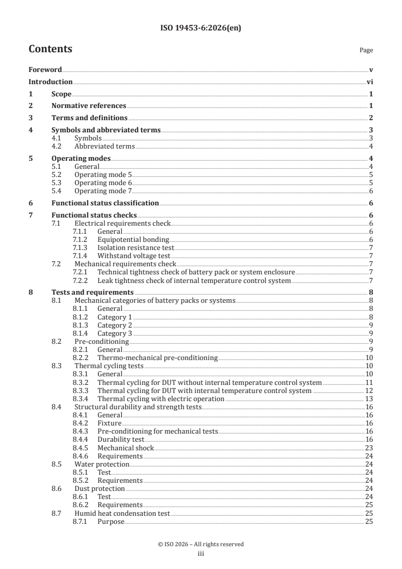
- Clause 8 Tests and requirements
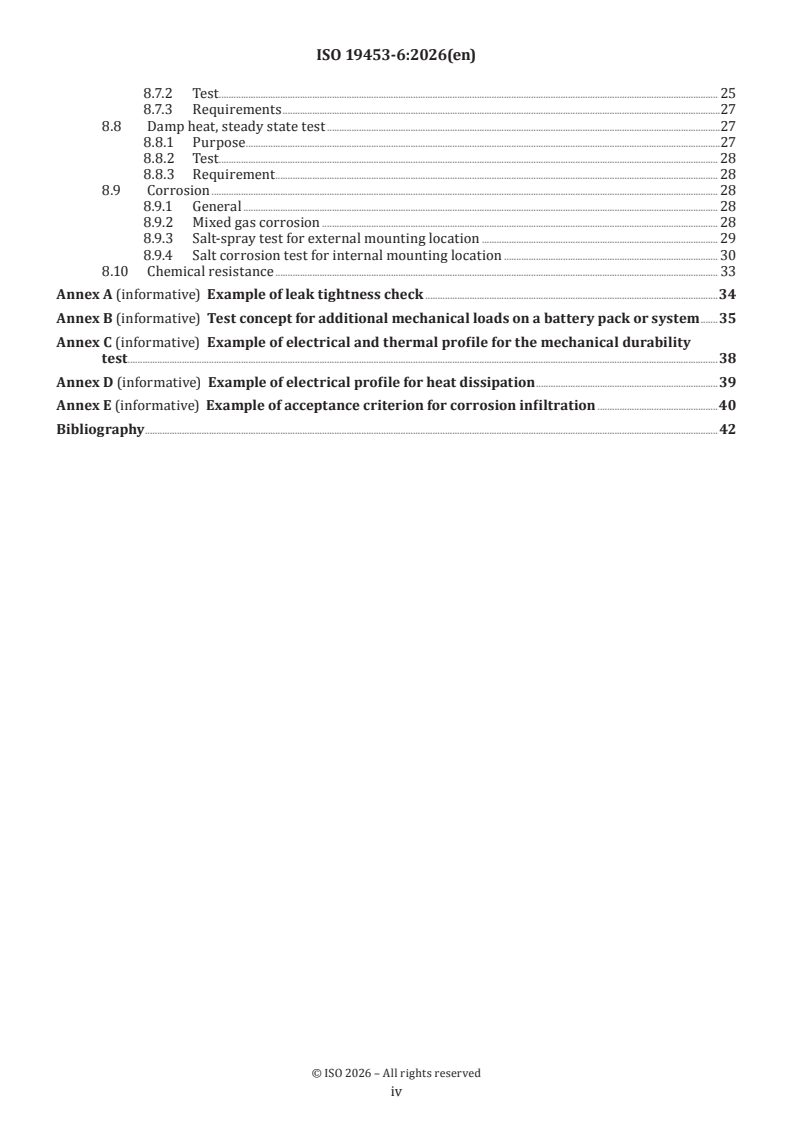
- Annexes A to E, all informative
| Annex | What it covers |
|---|---|
| Annex A | Example of leak tightness check |
| Annex B | Test concept for additional mechanical loads |
| Annex C | Example of electrical and thermal profile for the mechanical durability test |
| Annex D | Example of electrical profile for heat dissipation |
| Annex E | Example of acceptance criterion for corrosion infiltration |
What are the key requirements of ISO 19453-6:2026?
ISO 19453-6:2026 is built around agreed operating modes, mechanical categories, environmental tests and final functional checks. In practice, that means you need to define how the device under test (DUT) is configured, how it is loaded, what temperatures and vibrations it sees, and what must still work after the test.
Operating modes and test setup
Clause 5 defines operating modes 5, 6 and 7 for the DUT. They distinguish whether the pack is unsupplied or supplied, whether the battery management system (BMS) is operational, whether the main contactor is open or closed, whether the main power supply live part is active, and whether the internal temperature control system (ITCS) is deactivated or activated.
This matters because many tests depend on the exact operating mode. The document also says any autonomous functions, such as cell voltage balancing, have to be agreed between customer and supplier, and liquid-based ITCS setups need the intended liquid, nominal volume and pressure.
Functional status checks after testing
Clause 6 uses functional status classification from ISO 16750-1, together with parameter monitoring or a parameter test. Clause 7 then adds checks for insulation and enclosure tightness.
For voltage class B packs or systems, the electrical checks include:
- equipotential bonding
- isolation resistance
- withstand voltage
These are performed in accordance with ISO 6469-3 and are intended to show that the insulation system has survived the environmental sequence. Clause 7 also requires technical tightness checks of the enclosure, and a separate leak tightness check for the ITCS when a liquid medium is used.
Mechanical categories and vibration/shock severity
Clause 8.1 classifies battery packs or systems into three mechanical categories. Category 1 and 2 are point-mounted, while Category 3 covers large-area mounting or structural integration into the vehicle body.
That classification matters because it determines the vibration method, the need for vehicle-specific profiles, and whether additional loads such as torsion and bending should be considered. Category 1 and 2 use standard random vibration profiles; Category 3 uses vehicle-specific profiles and may need additional loads.
Pre-conditioning before mechanical tests
Clause 8.2 requires pre-conditioning to stabilize the DUT after assembly stress. For mechanical tests, thermo-mechanical pre-conditioning is mandatory and combines thermal cycling with electrical operation.
In practice, this prepares the pack for the durability and shock sequence and helps reveal defects that appear only after the pack has already been stressed once. The electrical pre-conditioning load profile is agreed between customer and supplier, or taken from an application-specific drive cycle.
Thermal cycling
Clauses 8.3.2 to 8.3.4 cover three thermal cycling variants:
- without ITCS
- with ITCS
- with electrical operation
The tests use operating mode 6.2, and for electrical heating effects also 7.2. Their purpose is to check for malfunction, cracks and breakage caused by temperature changes and thermal gradients. The pack temperature is monitored through internal sensors and BMS logic, so the test reflects how the system actually controls itself.
Structural durability, vibration and shock
Clause 8.4 combines random vibration, thermal cycling and electrical operation in one durability sequence. The pack is tested on all three axes, and the profile depends on the mechanical category.
Clause 8.4.5 then adds mechanical shock at both minimum and maximum state of charge (SOC), unless a justified single-SOC case is agreed. The result expected from the whole sequence is no breakage and functional status class A.
Water, dust, humidity, corrosion and chemical resistance
Clauses 8.5 to 8.10 cover ingress protection, dust, humid heat condensation, damp heat steady state, corrosion and chemical resistance. These tests are tied to ISO 20653, ISO 16750-4, ISO 16750-5, ISO 9227 and IEC 60068 methods.
For corrosion, the document distinguishes mixed gas corrosion, salt spray for external mounting locations, and salt corrosion for internal mounting locations. The corrosion-related checks use functional status class C, while the enclosure and sealing checks must still pass. The practical point is that mounting location changes the severity and the test method.
What terms does ISO 19453-6:2026 define?
- BMS - The battery management system controls, manages, detects or calculates electric and thermal functions of the battery pack or system and communicates with other vehicle controllers.
- ITCS - The internal temperature control system heats or cools the battery pack or system to a target temperature set by the BMS.
- main contactor - This is the switching or disconnecting device for the main power supply live part.
- main power supply live part - This is the conductor or conductive part intended to be energized during normal operation, excluding the Class A auxiliary voltage supply and the electric chassis.
- MAST - A multiaxial simulation table induces vibration or shock in all three axes of the DUT.
- PSD - Power spectral density is a measure of signal power versus frequency, used to describe random vibration.
- rated capacity - This is the total ampere-hours that can be withdrawn from a fully charged battery pack or system under defined manufacturer conditions.
- technical tightness - The inherent ability of a system to prevent fluids, gases or dust from passing through the enclosure.
Who uses ISO 19453-6:2026?
ISO 19453-6:2026 is used by vehicle manufacturers, traction battery suppliers, validation engineers, test laboratories and quality teams working on battery electric, hybrid electric and fuel cell electric road vehicles. It helps them agree test plans, choose operating modes, select severities by mounting location and define pass-fail checks after environmental exposure.
It is especially relevant when a battery pack or system must be validated for passenger cars and when customer and supplier need a shared basis for environmental and durability testing.
What changed in ISO 19453-6:2026 from the previous edition?
ISO 19453-6:2026 is the second edition and cancels and replaces ISO 19453-6:2020. The foreword states that the main technical change is the relinking of references to the withdrawn ISO 19453-1 to ISO 19453-5 sections after the merger of this series with the ISO 16750 (all parts) series.
Which standards are used with ISO 19453-6:2026?
ISO 19453-6:2026 relies on several companion standards and test methods:
- ISO 6469-3 - provides the electrical safety methods for equipotential bonding, isolation resistance and withstand voltage.
- ISO 9227 - provides the salt spray corrosion test basis.
- ISO 16750-1 - provides general terms, functional status classification and symbols used throughout the document.
- ISO 16750-4:2023 - provides climatic load methods used for dust and damp heat related testing.
- ISO 16750-5 - provides chemical load test conditions.
- ISO 20653 - provides IP code protection methods for water, dust and access.
- IEC 60068-2-14 - provides temperature change cycling.
- IEC 60068-2-27 - provides shock testing.
- IEC 60068-2-38 - provides composite temperature/humidity cyclic testing.
- IEC 60068-2-60 - provides mixed gas corrosion testing.
- IEC 60068-2-64 - provides broadband random vibration testing.
The document also refers to ISO 12405-4, ISO 16750-3, ISO 6270-2 and ISO 14993:2026 in examples and supporting discussion, mainly for load profiles, vibration reasoning and corrosion test context.
What does the ISO 19453-6:2026 document contain?
ISO 19453-6:2026 contains the operating mode definitions, mechanical classification scheme, functional status checks and a set of environmental test methods for traction battery packs and systems. It also includes detailed figures and tables for thermal cycling, vibration, shock, humidity, salt corrosion and mixed gas corrosion.
The informative annexes add practical examples rather than new requirements. They show how to check leak tightness, how to think about additional mechanical loads on structurally integrated packs, and how to build example electrical and thermal profiles for durability and heat dissipation tests.
For engineering and validation work, the document is useful as a test planning framework: it tells you what to define, what to control, what to monitor and what to verify after exposure.
Relations
- Effective Date
- 29-Jul-2023
Buy Documents
ISO 19453-6:2026 - Road vehicles — Environmental conditions and testing for electrical and electronic equipment for drive system of electric propulsion vehicles — Part 6: Traction battery packs and systems
Get Certified
Connect with accredited certification bodies for this standard

TÜV Rheinland
TÜV Rheinland is a leading international provider of technical services.

TÜV SÜD
TÜV SÜD is a trusted partner of choice for safety, security and sustainability solutions.

DEKRA Certification Inc.
DEKRA US certification services.
Sponsored listings
Frequently Asked Questions
ISO 19453-6:2026 is a standard published by the International Organization for Standardization (ISO). Its full title is "Road vehicles — Environmental conditions and testing for electrical and electronic equipment for drive system of electric propulsion vehicles — Part 6: Traction battery packs and systems". This standard covers: This document specifies requirements for lithium-ion traction battery packs or systems used in battery electric, hybrid electric and fuel cell electric road vehicles. This document describes the most relevant environmental stresses and specifies tests and test boundary conditions. This document establishes a classification of battery packs or systems and defines different stress levels for testing when a classification is applicable and required. The objective of this document is to specify standard test procedures and conditions to enable the observation of the reliability of the lithium-ion traction battery in the vehicle. This document specifies tests for a battery pack or system of voltage class A and B. This document provides the necessary information to set up a dedicated test plan for a battery pack or system subject to agreement between the customer and supplier. If required, the relevant test procedures and/or test conditions can also be selected from this document. NOTE This document only covers requirements and test conditions for a traction battery pack or system used in passenger cars.
This document specifies requirements for lithium-ion traction battery packs or systems used in battery electric, hybrid electric and fuel cell electric road vehicles. This document describes the most relevant environmental stresses and specifies tests and test boundary conditions. This document establishes a classification of battery packs or systems and defines different stress levels for testing when a classification is applicable and required. The objective of this document is to specify standard test procedures and conditions to enable the observation of the reliability of the lithium-ion traction battery in the vehicle. This document specifies tests for a battery pack or system of voltage class A and B. This document provides the necessary information to set up a dedicated test plan for a battery pack or system subject to agreement between the customer and supplier. If required, the relevant test procedures and/or test conditions can also be selected from this document. NOTE This document only covers requirements and test conditions for a traction battery pack or system used in passenger cars.
ISO 19453-6:2026 is classified under the following ICS (International Classification for Standards) categories: 43.040.10 - Electrical and electronic equipment. The ICS classification helps identify the subject area and facilitates finding related standards.
ISO 19453-6:2026 has the following relationships with other standards: It is inter standard links to ISO 19453-6:2020. Understanding these relationships helps ensure you are using the most current and applicable version of the standard.
ISO 19453-6:2026 is available in PDF format for immediate download after purchase. The document can be added to your cart and obtained through the secure checkout process. Digital delivery ensures instant access to the complete standard document.
Standards Content (Sample)
International
Standard
ISO 19453-6
Second edition
Road vehicles — Environmental
2026-09
conditions and testing for electrical
and electronic equipment for
drive system of electric propulsion
vehicles —
Part 6:
Traction battery packs and systems
Véhicules routiers — Spécifications d'environnement et essais
de l'équipement électrique et électronique pour les véhicules à
propulsion électrique —
Partie 6: Packs et systèmes de batterie de traction
Reference number
© ISO 2026
All rights reserved. Unless otherwise specified, or required in the context of its implementation, no part of this publication may
be reproduced or utilized otherwise in any form or by any means, electronic or mechanical, including photocopying, or posting on
the internet or an intranet, without prior written permission. Permission can be requested from either ISO at the address below
or ISO’s member body in the country of the requester.
ISO copyright office
CP 401 • Ch. de Blandonnet 8
CH-1214 Vernier, Geneva
Phone: +41 22 749 01 11
Email: copyright@iso.org
Website: www.iso.org
Published in Switzerland
ii
Contents Page
Foreword .v
Introduction .vi
1 Scope . 1
2 Normative references . 1
3 Terms and definitions . 2
4 Symbols and abbreviated terms. 3
4.1 Symbols .3
4.2 Abbreviated terms .4
5 Operating modes . 4
5.1 General .4
5.2 Operating mode 5 .5
5.3 Operating mode 6 .5
5.4 Operating mode 7 .6
6 Functional status classification . 6
7 Functional status checks . 6
7.1 Electrical requirements check . .6
7.1.1 General .6
7.1.2 Equipotential bonding .6
7.1.3 Isolation resistance test .7
7.1.4 Withstand voltage test .7
7.2 Mechanical requirements check .7
7.2.1 Technical tightness check of battery pack or system enclosure .7
7.2.2 Leak tightness check of internal temperature control system .7
8 Tests and requirements . 8
8.1 Mechanical categories of battery packs or systems .8
8.1.1 General .8
8.1.2 Category 1 .8
8.1.3 Category 2 .9
8.1.4 Category 3 .9
8.2 Pre-conditioning .9
8.2.1 General .9
8.2.2 Thermo-mechanical pre-conditioning .10
8.3 Thermal cycling tests .10
8.3.1 General .10
8.3.2 Thermal cycling for DUT without internal temperature control system .11
8.3.3 Thermal cycling for DUT with internal temperature control system . 12
8.3.4 Thermal cycling with electric operation . 13
8.4 Structural durability and strength tests .16
8.4.1 General .16
8.4.2 Fixture .16
8.4.3 Pre-conditioning for mechanical tests.16
8.4.4 Durability test .16
8.4.5 Mechanical shock . 23
8.4.6 Requirements .24
8.5 Water protection . .24
8.5.1 Test . . .24
8.5.2 Requirements .24
8.6 Dust protection .24
8.6.1 Test . . .24
8.6.2 Requirements . 25
8.7 Humid heat condensation test . 25
8.7.1 Purpose . 25
iii
8.7.2 Test . . . 25
8.7.3 Requirements .27
8.8 Damp heat, steady state test .27
8.8.1 Purpose .27
8.8.2 Test . . . 28
8.8.3 Requirement . 28
8.9 Corrosion . 28
8.9.1 General . 28
8.9.2 Mixed gas corrosion . 28
8.9.3 Salt-spray test for external mounting location . 29
8.9.4 Salt corrosion test for internal mounting location . 30
8.10 Chemical resistance . 33
Annex A (informative) Example of leak tightness check .34
Annex B (informative) Test concept for additional mechanical loads on a battery pack or system .35
Annex C (informative) Example of electrical and thermal profile for the mechanical durability
test .38
Annex D (informative) Example of electrical profile for heat dissipation .39
Annex E (informative) Example of acceptance criterion for corrosion infiltration .40
Bibliography .42
iv
Foreword
ISO (the International Organization for Standardization) is a worldwide federation of national standards
bodies (ISO member bodies). The work of preparing International Standards is normally carried out through
ISO technical committees. Each member body interested in a subject for which a technical committee has
been established has the right to be represented on that committee. International organizations,
governmental and non-governmental, in liaison with ISO, also take part in the work. ISO collaborates closely
with the International Electrotechnical Commission (IEC) on all matters of electrotechnical standardization.
The procedures used to develop this document and those intended for its further maintenance are described
in the ISO/IEC Directives, Part 1. In particular, the different approval criteria needed for the different types
of ISO documents should be noted. This document was drafted in accordance with the editorial rules of the
ISO/IEC Directives, Part 2 (see www.iso.org/directives).
ISO draws attention to the possibility that the implementation of this document may involve the use of (a)
patent(s). ISO takes no position concerning the evidence, validity or applicability of any claimed patent
rights in respect thereof. As of the date of publication of this document, ISO had not received notice of (a)
patent(s) which may be required to implement this document. However, implementers are cautioned that
this may not represent the latest information, which may be obtained from the patent database available at
www.iso.org/patents. ISO shall not be held responsible for identifying any or all such patent rights.
Any trade name used in this document is information given for the convenience of users and does not
constitute an endorsement.
For an explanation of the voluntary nature of standards, the meaning of ISO specific terms and expressions
related to conformity assessment, as well as information about ISO's adherence to the World Trade
Organization (WTO) principles in the Technical Barriers to Trade (TBT) see www.iso.org/iso/foreword.html.
This document was prepared by Technical Committee ISO/TC 22, Road vehicles, Subcommittee SC 32,
Electrical and electronic components and general system aspects.
This second edition cancels and replaces the first edition (ISO 19453-6:2020), which has been technically
revised.
The main changes are as follows:
— relinking references to the withdrawn ISO 19453-1 to ISO 19453-5 with the corresponding sections after
[1]
the merger of this series with the ISO 16750 (all parts) series.
[1]
A list of all parts in the ISO 16750 (all parts) series can be found on the ISO website.
Any feedback or questions on this document should be directed to the user’s national standards body. A
complete listing of these bodies can be found at www.iso.org/members.html.
v
Introduction
For over fifty years, traction batteries for electric vehicles have been developed to achieve high energy
density and high-power output. Specifically, lead-acid battery, Ni-Cd battery and Ni-MH battery with
aqueous electrolyte were most applied to electric vehicles in the early days. Thermal activated batteries,
such as molten salt batteries, like sodium sulfur battery, and Zebra battery, were also examined. Lithium-ion
battery penetrated the consumer market in portable battery application from 1991. Currently, it is the most
[2]
promising candidate of traction battery for electric vehicles. ISO 6469-1 specifies safety requirement for
[3]
rechargeable energy storage system (RESS), and the ISO 12405 (all parts) series was published to specify
performance and reliability tests. This document focuses on environmental and endurance tests of lithium-
ion battery systems.
[1]
The ISO 16750 (all parts) series specifies the test conditions on environment and reliability for
[1]
electrical and electric equipment for road vehicles. For the 2023 edition of the ISO 16750 (all parts)
[4]
series, the corresponding parts of the ISO 19453 (all parts) series were merged and reflected into their
[1]
ISO 16750 (all parts) counterparts. The battery pack or system is the electric system which charges and
[5]
discharges electricity through the converter. The test condition for mechanical load in ISO 16750-3 is
too severe to apply to the battery pack or system from the standpoint of frequency range and amplitude
[6]
of vibration in the test input spectrum. The test conditions for climatic load in ISO 16750-4 are also
excessive to apply to the battery pack or system, because the lithium-ion battery pack is designed to control
temperature within an adequate operational range. That is the reason why appropriate conditions for the
lithium-ion battery are specified in this document.
The purpose of this document is to assist its user in systematically defining, applying or both, a set of
internationally accepted environmental conditions, tests and operating requirements, which are based on
the anticipated actual environment in which the equipment will be operated and exposed to during its life
cycle. This document has been developed based on fundamental investigations and vehicle measurements
on voltage class A and B battery pack/system. The following environmental factors have been considered in
the development:
— World geography and climate
Electric propulsion vehicles are operated in nearly all terrestrial regions of the earth. Significant variation in
environmental conditions due to climatic environment, including diurnal and seasonal cycles, can therefore
be expected. Consideration has been given to worldwide ranges in the temperature, humidity, precipitation
and atmospheric conditions, including dust, pollution and altitude.
— Type of electric propulsion vehicle
Operating environment in an electric propulsion vehicle can depend on its electric powertrain architecture,
as well as its mass, size, supply voltage and so on. Consideration has been given to typical types of series
production electric propulsion vehicle architectures, such as hybrid electric vehicles, battery electric
vehicles, range extender hybrid electric vehicles, and fuel cell vehicles, but not including equipment specific
for fuel cell system.
— Vehicle use conditions and operating modes
Environmental conditions in and on the vehicle vary significantly with vehicle use (e.g. driving, charging
during parking, etc.). Operating modes, such as starting, driving, braking, stopping and so on, have been
considered, in particular, for traction battery system.
— Battery durability
For battery system, it is necessary to be resistant to environmental conditions experienced during
manufacture, shipping, handling, storage, vehicle assembly, vehicle usage and vehicle maintenance and
repair.
— Component mass and volume
The mass of battery pack is generally in the range of around 20 kg up to 60 kg for HEV, 80 kg to 150 kg
for PHEV, and more than 200 kg for BEV (weight assumptions from the year 2020). The battery pack has
vi
generally a large volume and thermal capacity. It is necessary, not only to prepare a large chamber, but it will
also take a long time to keep the thermal equivalent when performing a thermal shock test.
— Mounting location in the vehicle
HEV battery packs are generally installed inside the vehicle, PHEV battery packs are installed both outside
and inside, and BEV battery packs are generally installed outside. The environmental condition, such as
water splashing, dust, salt spray, humidity or corrosion for battery packs installed outside the vehicle
interior is more severe than for battery packs installed inside. In this document, test conditions are specified
according to mounting location.
a) Applicability to manufacturers’ responsibility
Due to technology limitations or variations in vehicle design, the vehicle manufacturer may be required to
place a component in a location where it cannot withstand the environmental conditions described in the
[1]
ISO 16750 (all parts) series. Under these circumstances, it is the responsibility of the vehicle manufacturer
to provide the necessary environmental protection.
b) Applicability to wiring harnesses, cables and electrical connectors
[1]
Although some environmental conditions and tests in the ISO 16750 (all parts) series may be relevant to
vehicle wiring harnesses, cables and connectors, its scope is not sufficient to be used as a complete standard.
[1]
It is, therefore, not recommended that the ISO 16750 (all parts) series be directly applied to such devices
and equipment.
c) Applicability to parts or assemblies inside the equipment
[1]
The ISO 16750 (all parts) series describes environmental conditions and tests to be applied to electrical
and electronic equipment directly mounted in or on the vehicle. It is not intended for direct application to
[1]
parts or assemblies that are part of the equipment. For example, the ISO 16750 (all parts) series should
not be directly applied to integrated circuits (ICs) and discrete components, electrical connectors, printed
circuit boards (PCBs), gauges, etc., that are attached in or on the equipment. Electrical, mechanical, climatic
and chemical loads for such parts and assemblies can be quite different from those described in the
[1]
ISO 16750 (all parts) series.
[1]
On the other hand, it is desirable to use the ISO 16750 (all parts) series to help derive environmental
conditions and test requirements for parts and assemblies that are intended for use in road vehicle
equipment. For example, a temperature range from −40 °C to 90 °C may be specified for parts or assemblies
contained inside a piece of equipment having a temperature range of −40 °C to 70 °C and an additional
temperature rise of 20 K.
d) Applicability relative to system integration and validation
[1]
The user of the ISO 16750 (all parts) series is cautioned to understand that its scope is limited to conditions
and testing at the equipment level and, therefore, does not represent all conditions and testing necessary for
complete verification and validation of the vehicle system, for example, cold water shock tests were omitted
from this document. Environmental and reliability testing of equipment parts and vehicle systems can be
[1]
required. For example, the ISO 16750 (all parts) series does not necessarily ensure that environmental
and reliability requirements for solder joints, solderless connections, integrated circuits and so on are met.
Such items are assured at the part, material or assembly level. Additionally, vehicle and system level testing
might be required to validate the equipment in the vehicle application.
vii
International Standard ISO 19453-6:2026(en)
Road vehicles — Environmental conditions and testing for
electrical and electronic equipment for drive system of
electric propulsion vehicles —
Part 6:
Traction battery packs and systems
1 Scope
This document specifies requirements for lithium-ion traction battery packs or systems used in battery
electric, hybrid electric and fuel cell electric road vehicles. This document describes the most relevant
environmental stresses and specifies tests and test boundary conditions. This document establishes a
classification of battery packs or systems and defines different stress levels for testing when a classification
is applicable and required. The objective of this document is to specify standard test procedures and
conditions to enable the observation of the reliability of the lithium-ion traction battery in the vehicle.
This document specifies tests for a battery pack or system of voltage class A and B.
This document provides the necessary information to set up a dedicated test plan for a battery pack or
system subject to agreement between the customer and supplier. If required, the relevant test procedures
and/or test conditions can also be selected from this document.
NOTE This document only covers requirements and test conditions for a traction battery pack or system used in
passenger cars.
2 Normative references
The following documents are referred to in the text in such a way that some or all of their content constitutes
requirements of this document. For dated references, only the edition cited applies. For undated references,
the latest edition of the referenced document (including any amendments) applies.
ISO 6469-3, Electrically propelled road vehicles — Safety specifications — Part 3: Electrical safety
ISO 9227, Corrosion tests in artificial atmospheres — Salt spray tests
ISO 16750-1, Road vehicles — Environmental conditions and testing for electrical and electronic equipment —
Part 1: General
ISO 16750-4, Road vehicles — Environmental conditions and testing for electrical and electronic equipment —
Part 4: Climatic loads
ISO 16750-4:2023, Road vehicles — Environmental conditions and testing for electrical and electronic equipment
— Part 4: Climatic loads
ISO 16750-5, Road vehicles — Environmental conditions and testing for electrical and electronic equipment —
Part 5: Chemical loads
ISO 20653, Road vehicles — Degrees of protection (IP code) — Protection of electrical equipment against foreign
objects, water and access
IEC 60068-2-14, Environmental testing - Part 2-14: Tests - Test N: Change of temperature
IEC 60068-2-27, Environmental testing - Part 2-27: Tests - Test Ea and guidance: Shock
IEC 60068-2-38, Environmental testing - Part 2-38: Tests - Test Z/AD: Composite temperature/humidity cyclic
test
IEC 60068-2-60, Environmental testing - Part 2-60: Tests - Test Ke: Flowing mixed gas corrosion test
IEC 60068-2-64, Environmental testing - Part 2-64: Tests - Test Fh: Vibration, broadband random and guidance
3 Terms and definitions
For the purposes of this document, the terms and definitions given in ISO 16750-1, ISO 20653 and the
following apply.
ISO and IEC maintain terminological databases for use in standardization at the following addresses:
— ISO Online browsing platform: available at https:// www .iso .org/ obp
— IEC Electropedia: available at http:// www .electropedia .org/
3.1
BMS
battery management system
electronic system that controls, manages, detects or calculates electric and thermal functions of the battery
pack or system and that provides communication between the battery pack or system and other vehicle
controllers
3.2
ITCS
internal temperature control system
internal thermal management system of a battery pack or system that can heat or cool the battery pack or
system to a target temperature determined by the battery management system (BMS) (3.1)
EXAMPLE Liquid-based heating/cooling system.
3.3
main contactor
electronic or mechanic switching/disconnecting device for the battery pack or system main power supply
live part (3.4)
3.4
main power supply live part
conductor or conductive part intended to be energized during normal operation, but explicitly excluding
the Class A auxiliary voltage supply and the electric chassis, which is defined as the vehicle's electrically
connected conductive parts serving as a reference potential
3.5
MAST
multiaxial simulation table
multiaxial system to induce vibrations or shocks in all three axial dimensions to the device under test (DUT)
3.6
PSD
power spectral density
measure of signal's power content versus frequency
Note 1 to entry: A power spectral density (PSD) is typically used to characterize broadband random signals. The
amplitude of the power spectral density (PSD) is normalized by the spectral resolution employed to digitize the signal.
3.7
rated capacity
total number of ampere-hours that can be withdrawn from a fully charged battery pack or system under
test conditions defined by the battery pack or system manufacturer
3.8
technical tightness
inherent characteristic of a system that prevent fluids, gases or dusts from passing from the external to the
internal environment or from the internal to the external environment, or both
4 Symbols and abbreviated terms
4.1 Symbols
1C One-hour charge or discharge rate for the rated battery pack or system capacity
C/3 Three-hour charge or discharge rate for the rated battery pack or system capacity
RT Room temperature value as defined in ISO 16750-1
t Duration with an electrical current charging the battery pack or system
ch
t Duration with an electrical current discharging the battery pack or system
dch
T Ambient temperature of a climate/temperature chamber
amb
T Temperature of the internal temperature control system, for example liquid coolant, of a bat-
ITCS
tery pack or system
T Highest ambient temperature of a battery pack or system specified by the manufacturer (e.g.
max
storage)
*
T Maximum temperature by electric operation, can be lower than T
max max
T Highest operating temperature of a battery pack or system specified by the manufacturer
max,DUT
T Highest temperature at which an internal temperature control system, for example liquid
max,ITCS
coolant, of a battery pack or system can be used. Specified by the manufacturer
T Lowest ambient temperature of a battery pack or system specified by the manufacturer (e.g.
min
storage)
*
T Low temperature, allows large currents, can be higher than T
min min
T Lowest operating temperature of a battery pack or system specified by the manufacturer
min,DUT
T Lowest temperature at which an internal temperature control system, for example liquid
min,ITCS
coolant, of a battery pack or system can be used. Specified by the manufacturer
X-axis Vehicle driving direction
Y-axis Perpendicular to vehicle driving direction and vertical axis
Z-axis Vertical axis
4.2 Abbreviated terms
CC/CV Constant current/constant voltage
DOF Degrees of freedom
Device under test. Referring to battery pack or system used for electrically propelled road
DUT
vehicles
State of charge. Available capacity in a battery pack or system expressed as a percentage of
SOC
rated capacity
5 Operating modes
5.1 General
An overview of the DUT operating modes according to this document is given in Table 1.
Operating modes defined in ISO 16750-1 cannot be applied because modes that are more specific are
required for a battery pack or system.
Operation of the battery pack or system with autonomous functions, for example, cell voltage balancing, in
any of the operating modes shall be agreed between customer and supplier.
Table 1 — DUT operating modes
Operating Class A auxiliary Battery man- Main contactor Electrical op- Internal tem-
mode voltage agement system eration of main perature control
(BMS) power supply live system
part
5.1 Unsupplied Non-operational Open No Deactivated
5.2 Unsupplied Non-operational Open No Deactivated
6.1 Supplied Non-operational Open No Deactivated
6.2 Supplied Operational Open No Deactivated
6.3 Supplied Operational Closed No Deactivated
7.1 Supplied Operational Closed Yes Deactivated
7.2 Supplied Operational Closed Yes Activated
[7]
NOTE 1 Auxiliary voltage class A according to ISO 12405-4 refers to the voltage supply of the BMS with U or U as defined
A B
[8]
in ISO 16750-1 .
NOTE 2 The difference between operating mode 5.1 and 5.2 is the presence of the wiring harness and the connection to all
interfaces.
NOTE 3 The difference between operating mode 7.1 and 7.2 is that in operating mode 7.2 an ITCS is required due to self-
heating effects caused by system activation.
NOTE 4 The conditions for an activated ITCS are set and controlled by the BMS regarding the thermal management strategy
and the operational limits of the battery pack or system. If the ITCS is deactivated, it has no function. With deactivated ITCS,
safety measures to limit the DUT temperature are still allowed at any time.
If the electronic control unit of a battery pack or system cannot provide the necessary BMS functionality,
appropriate additional electric and/or electronic controllers to provide BMS functionality may be used in
agreement between customer and supplier.
If the DUT has an internal temperature control system, the thermal management system and the
corresponding conditioning loop at the test bench equipment shall be operational according to the given
test specifications and controlled by the BMS. For the requested test procedure, the thermal management
strategy and operational limits of the DUT shall be met.
Some test methods in this document require intended temperature settings for the ITCS beyond the thermal
management strategy of the DUT controlled by the BMS. For these test procedures, the thermal management
system and conditioning loop at the test bench equipment are controlled externally by the test equipment
according to the test specifications but within the battery system operational and safety limits.
If a liquid-based internal temperature control system is used in the battery pack, the liquid circulating
system shall be filled with the intended liquid (heat transfer medium) of the nominal volume and pressure.
Up until operating mode 6.3 without use of the temperature control system, the openings can be sealed
accordingly. If the fluid system is operated, the nominal flow rate as specified by the manufacturer should
be used.
[9]
NOTE 1 For further information on the preparation of the DUT for testing, see ISO 12405-4:2018 , 5.4.
NOTE 2 Pressure compensating devices can be needed for testing with liquid based internal temperature control
systems.
5.2 Operating mode 5
No external voltages are applied to the DUT. The main contactor, if present, shall be opened.
— Operating mode 5.1
— Not connected to wiring harness or any electrical interconnections or interfaces. Protective caps for
the electrical interconnections and interfaces can be present.
— Operating mode 5.2
— Connected to wiring harness including all electrical interconnections and interfaces simulating
vehicle installation.
5.3 Operating mode 6
The DUT with all electrical connections made and connected to all interfaces is electrically operated with
class A auxiliary supply voltage U as defined in ISO 16750-1, as in a vehicle with shut-off engine, but without
B
operating load for the main power supply live part of the battery pack or system.
— Operating mode 6.1
— BMS functions are not operational, no communication.
— Battery pack or system shall be without electric operation (e.g. charging, discharging).
— Main contactor, if present, shall be opened.
— Operating mode 6.2
— BMS shall be fully operational according to the test specification.
— Battery pack or system shall be without electric operation (e.g. charging, discharging).
— Main contactor, if present, shall be opened.
— Operating mode 6.3
— BMS shall be fully operational according to the test specification.
— Battery pack or system shall be without electric operation (e.g. charging, discharging).
— Main contactor, if present, shall be closed.
5.4 Operating mode 7
The DUT with all electrical connections made and connected to all interfaces is electrically operated with
class A auxiliary voltage U as defined in ISO 16750-1 and with auxiliary machines, for example, cooling
B
system etc. The main contactor, if present, shall be closed.
— Operating mode 7.1
— BMS shall be fully operational according to the test specification.
— Battery pack or system with control in an electrical operating mode in which, if present, the ITCS is
not operational.
— Operating mode 7.2
— BMS shall be fully operational according to the test specification.
— Battery pack or system shall be within control in a typical electrical operating mode, in which if
needed, the ITCS is operational.
6 Functional status classification
Functional status classification is as defined in ISO 16750-1.
The verification of the required functional status takes place by means of continuous parameter monitoring
or a parameter test.
Relevant control and test signals should be logged with sufficient resolution. Battery cycler and climate
chamber data should be monitored.
7 Functional status checks
7.1 Electrical requirements check
7.1.1 General
The tests described below are intended to ensure the insulation performance of the basic insulation measure
of a voltage class B battery pack or system after completing environmental tests. The described tests shall be
performed at the end of a sequence of environmental tests. If only a single environmental test is performed,
they shall be performed afterwards.
NOTE 1 Performing the test sequence of an isolation resistance test followed by a withstand voltage test, and finally
a second isolation resistance test allows to determine whether the applied voltage level of the withstand voltage
test had a permanent degrading effect on the insulation or not.
NOTE 2 Although not required for a voltage class A battery pack or system, the tests described in this section can
technically also be applied to a voltage class A component, if applicable.
7.1.2 Equipotential bonding
This test ensures the required electrical resistances for equipotential bonding of conductively connected
parts of the DUT, in particular as requirement for 7.1.3 and 7.1.4.
The equipotential bonding test shall be performed in accordance with ISO 6469-3.
The electrical resistance value shall meet the requirements of ISO 6469-3.
7.1.3 Isolation resistance test
The isolation resistance test measures the resistance value between main power supply live part and
conductive parts of the DUT.
The isolation resistance test shall be performed in accordance with ISO 6469-3.
The isolation resistance value shall meet the requirements of ISO 6469-3.
7.1.4 Withstand voltage test
This test ensures the dielectric withstand voltage capability and detects pre-damaged parts of the insulation
measure and weak points in the design, for example, by conductive particles originating from production or
rework, that could result in a failure of the insulation measure at later stages.
The withstand voltage test shall be performed in accordance with ISO 6469-3.
The requirements of ISO 6469-3 shall be met.
7.2 Mechanical requirements check
7.2.1 Technical tightness check of battery pack or system enclosure
The purpose of this test is to verify the technical tightness of the battery pack or system enclosure according
to the desired degree of protection.
The method to check the technical tightness of the traction battery pack or system enclosure with specified
degrees of protection, in accordance with ISO 20653, via non-destructive tests and acceptance criteria, shall
be agreed between customer and supplier.
[10] [11] [12] [13]
NOTE Non-destructive leak test techniques are listed in ISO 20653 or EN 1779 . EN 13184 , EN 13185
[14] [11]
and EN 1593 support the implementation of techniques according to EN 1779 .
The test method shall describe at least the following items:
— technique used;
— pre-condition(s) (e.g. required room temperature, required acclimation time of the DUT at room
temperature, condition of pressure compensation device);
— action(s);
— post condition(s);
— pass criteria;
— documentation content in test report;
— equipment.
7.2.2 Leak tightness check of internal temperature control system
The purpose of this test is to verify the leak tightness of the ITCS of the battery pack or system. The test shall
only be performed if the DUT has a liquid medium for the ITCS, for example, internal or external cooling-
circuit.
The method for the leak test of the ITCS shall be agreed between customer and supplier.
The acceptance criteria shall be agreed between customer and supplier in order to satisfy the design
requirement.
NOTE 1 This test can be performed with a pressure loss test, pressure difference, leakage volume or according to
[15]
EN 1779:1999 , Annex A, using a tracer gas in conjunction with a leak detector.
NOTE 2 An exemplary description of a leak tightness check is given in Annex A.
8 Tests and requirements
8.1 Mechanical categories of battery packs or systems
8.1.1 General
Traction battery packs or systems for electric vehicles have a wide range of sizes and masses, as well as a
variety of mounting locations in the vehicle. Linked to these parameters is the strength of vehicle and DUT
interaction, such as torsional forces. Taking all these factors into account, battery packs or systems shall be
divided into thre
...