

ISO/DTR 20590
(Main)Space systems — Space debris mitigation design and operation manual for launch vehicle orbital stages
- Abstract
This document contains information on the design and operational practices for launch vehicle orbital stages for mitigating space debris. This document provides information to engineers on the requirements and recommendations in the space debris mitigation standards to reduce the growth of space debris by ensuring that launch vehicle orbital stages are designed, operated, and disposed of in a manner that prevents them from generating debris throughout their orbital lifetime.
- Status
- Not Published
- Technical Committee
- ISO/TC 20/SC 14 - Space systems and operations
- Drafting Committee
- ISO/TC 20/SC 14/WG 7 - Orbital Debris Working Group
- Current Stage
- 5092 - FDIS referred back to TC or SC
- Start Date
- 23-Oct-2026
- Completion Date
- 24-Oct-2026
Buy Documents

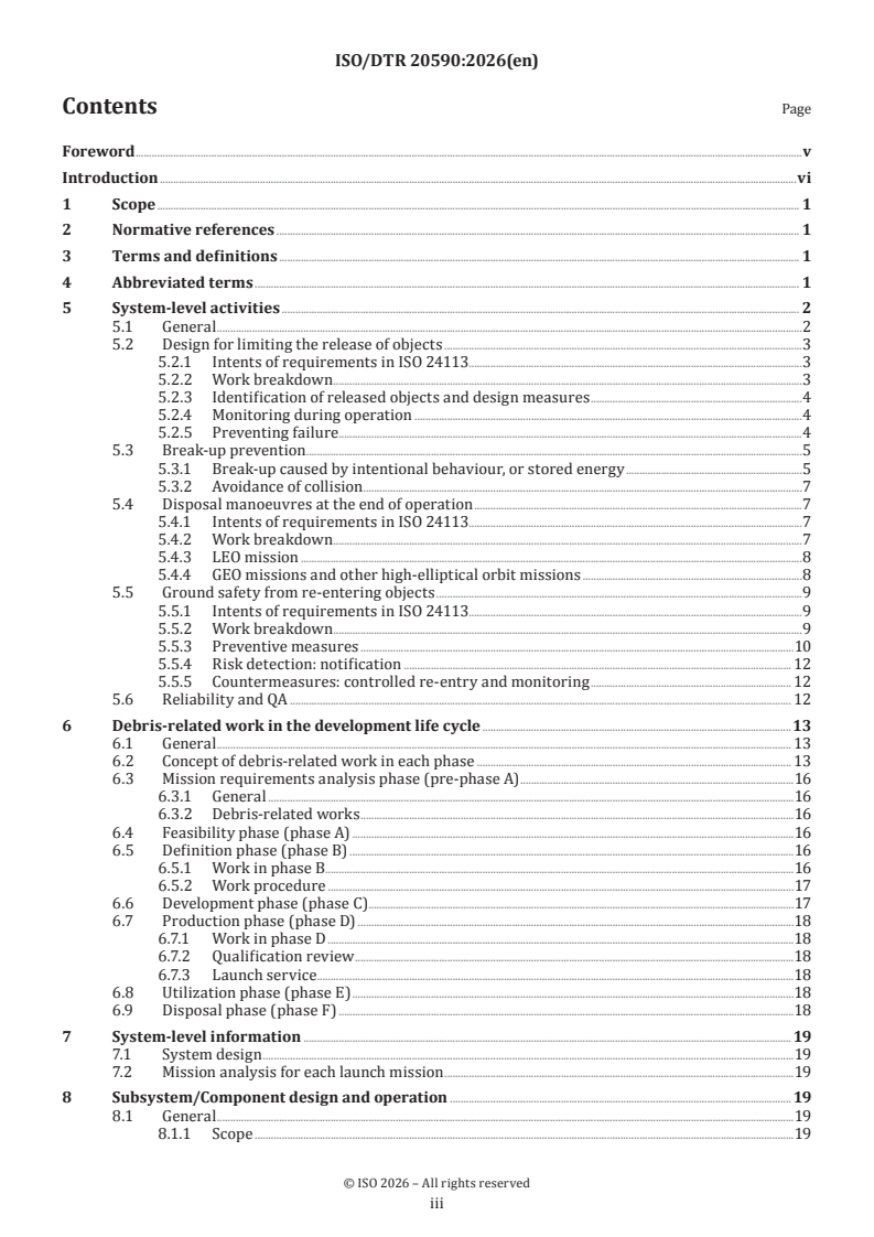
ISO/DTR 20590 - Space systems — Space debris mitigation design and operation manual for launch vehicle orbital stages

REDLINE ISO/DTR 20590 - Space systems — Space debris mitigation design and operation manual for launch vehicle orbital stages
ISO/TR 20590 is an ISO technical report for space systems. It explains design and operational practices for launch vehicle orbital stages so engineers can apply space debris mitigation requirements and recommendations from ISO 24113 and ISO 20893. The document is written to help reduce debris growth by showing how these stages are designed, operated, disposed of, and checked across their orbital lifetime.
What does ISO/TR 20590 specify?
ISO/TR 20590 gives guidance for launch vehicle orbital stages with a focus on preventing them from creating debris. It is a manual for engineers and project teams who need to turn debris mitigation requirements into design, operation, and disposal practices.
The document is organized into:
- Clause 5 - system-level activities
- Clause 6 - debris-related work across the development life cycle
- Clause 7 - system-level information
- Clause 8 - subsystem and component design and operation
Clause 5 covers the main mitigation topics: limiting released objects, preventing break-up, planning disposal manoeuvres, protecting people on the ground from re-entering objects, and managing reliability and QA. Clause 6 places those topics into project phases from early requirements work through disposal, while Clauses 7 and 8 show how the system concept and each subsystem are affected in practice.
What are the key requirements of ISO/TR 20590?
System-level debris control starts early
ISO/TR 20590 treats debris mitigation as a system-level activity that begins in the earliest project phases and continues through disposal. Clause 5 emphasizes identifying debris-related requirements, deciding how to conform to them, applying mitigation measures during development and manufacturing, and carrying them through operation and disposal.
In practice, that means the launch vehicle orbital stage is not designed first and checked later for debris issues. The debris mitigation approach shapes the mission concept, the hardware allocation, the operations sequence, and the disposal plan from the start.
Clause 5 focuses on five main mitigation areas
ISO/TR 20590 says the main system-level subjects are limiting release of objects, preventing fragmentation in orbit, proper end-of-operation disposal, reducing ground hazards from re-entering debris, and ensuring quality, safety, and reliability. Clause 5 also gives work breakdowns for these topics and links them to the requirements in ISO 24113 and ISO 20893.
For readers, the practical point is that each area needs its own design choices and verification thinking. A stage may need to avoid releasing hardware in normal operation, prevent stored-energy failures, reserve propellant for disposal, and still meet re-entry safety expectations if it can return over the Earth.
Break-up prevention includes intentional and accidental events
ISO/TR 20590 explains break-up prevention as a combination of design measures, monitoring, and end-of-operation passivation. Clause 5 points to sources such as propulsion hardware, batteries, pressure vessels, and range safety self-destruct systems.
This matters because break-up can happen during operation or after the mission is over. The document therefore stresses removing residual energy, venting where needed, avoiding accidental activation of self-destruct hardware, and using failure analysis methods to confirm the risk is controlled.
Disposal planning depends on orbit and mission profile
ISO/TR 20590 describes disposal as a planned activity, not an afterthought. Clause 5 links disposal to estimating orbital lifetime, defining a disposal manoeuvre plan, selecting the disposal method for the mission, and providing the functions needed to execute it.
For launch vehicle orbital stages, the disposal approach depends on where the stage flies. The document discusses low Earth orbit, geostationary Earth orbit, geosynchronous transfer orbit, and other elliptical missions, and it points readers to orbit lifetime estimation tools and procedures for choosing an appropriate disposal concept.
Ground safety is handled through hazard analysis and controlled re-entry
ISO/TR 20590 includes a separate treatment of ground safety from re-entering objects. Clause 5 calls for identifying re-entry safety requirements, carrying out hazard analysis, and choosing design measures that reduce casualty risk and environmental pollution.
In practice, this means the team may need to design for demise, assess whether controlled re-entry is needed, prepare notifications for affected air and maritime authorities, and monitor the re-entry sequence. The document also makes clear that controlled re-entry can affect propulsion, avionics, power, communications, and the overall mission timeline.
Clause 6 puts debris work into the life cycle
ISO/TR 20590 links debris mitigation to each development phase from pre-phase A through disposal phase F. Clause 6 shows what the project is expected to do at each stage, including requirement identification, concept selection, specification drafting, detailed design, production qualification, operation, and disposal.
This is important in practice because debris decisions affect reviews such as SRR, PDR, CDR, and QR. The document shows that disposal propellant, re-entry control, reliability allocation, and monitoring functions need to be fixed early enough to influence the system specifications.
Clause 8 translates the subject into subsystem design
ISO/TR 20590 then breaks the guidance down by subsystem: propulsion, guidance and control, electric power-supply, communication, structure, and range safety. Clause 8 maps debris issues to each subsystem and explains the design implications for each one.
For engineers, this is where the document becomes directly usable. It covers topics such as solid motor slag, propellant tank venting, battery design, radiation hardness for controlled re-entry, maintaining command links, avoiding release of structural parts, and preventing accidental self-destruct activation.
What terms does ISO/TR 20590 define?
ISO/TR 20590 uses the terms and definitions from ISO 24113 and ISO 20893, and it also uses these abbreviations:
- EOMDP - end-of-mission (operation) disposal plan, the plan that defines how the stage will be disposed of at the end of operation.
- SDMP - space-debris-mitigation plan, the document that captures the chosen mitigation concept and its implementation.
- FDIR - failure detection, isolation and recovery, the set of functions used to detect faults and prevent them from turning into break-ups.
- QA - quality assurance, the project discipline that supports conformity, reliability, and controlled production.
- LEO - low Earth orbit, a regime where disposal lifetime and re-entry issues are especially important.
- GEO - geostationary Earth orbit, a protected region that the document treats as a key concern for disposal planning.
- GTO - geosynchronous transfer orbit, an orbit type discussed in relation to disposal lifetime and protected-region interference.
Who uses ISO/TR 20590?
ISO/TR 20590 is used by engineers working on launch vehicle orbital stages, especially those responsible for propulsion, guidance and control, electric power, communications, structures, and range safety. It is also relevant to mission assurance, reliability, and QA teams because the document links debris mitigation to failure prevention and disposal success.
Launch service providers and integrators use it when they define mission requirements, allocate propellant for disposal, plan controlled re-entry, and prepare launch and disposal sequences. Quality managers and buyers can use it to understand what debris-related design and operational topics need to be covered before a launch vehicle orbital stage is accepted for service.
What changed in ISO/TR 20590 from the previous edition?
ISO/TR 20590 is the third edition and it replaces ISO/TR 20590:2021. The main stated changes are:
- the text was updated to align with ISO 24113:2023
- break-up prevention information was revised after the cancellation of ISO 16127, in line with ISO 24113:2023 Clause 7.2 and ISO 20893 Clause 5
- disposal information was revised after the cancellation of ISO 16164, in line with ISO 20893 Clause 6
- Clause 5.3.1.4 adds the rationale for restricting anti-satellite missile testing as a means of intentional destruction
- other changes related to ISO 24113:2023 were added
Which standards are used with ISO/TR 20590?
ISO/TR 20590 refers to these standards as the main documents used alongside it:
| Standard | What it contributes |
|---|---|
| ISO 24113:2023 | The main space debris mitigation requirements used throughout the report |
| ISO 20893:2021 | Detailed debris mitigation requirements for launch vehicle orbital stages |
| ISO 27852:2024 | Orbit lifetime estimation methods and tools |
| ISO 27875 | Re-entry risk management for unmanned spacecraft and launch vehicle orbital stages |
| ISO 21740:2025 | Launch window estimation and collision avoidance |
| ISO 27025 | Product quality assurance requirements |
| ISO 23460 | Dependability assurance requirements |
| ISO 14300-1:2011 | Project structuring and life-cycle phase framing |
| ISO 23312:2022 | Detailed debris mitigation requirements for spacecraft, used as a related dependability reference |
What does the ISO/TR 20590 document contain?
ISO/TR 20590 contains work-breakdown tables that connect debris mitigation goals to concrete actions. It includes tables for preventing release of debris, preventing break-up, preserving protected orbital regions, and assuring ground safety from re-entry.
The document also contains life-cycle phase guidance, system design considerations, and subsystem-level design topics for propulsion, guidance and control, power supply, communication, structure, and range safety. It discusses methods and procedures for disposal planning, orbital lifetime estimation, controlled re-entry, passivation, venting, monitoring, and radiation-hardness considerations.
Relations
- Effective Date
- 01-Mar-2025
Buy Documents
ISO/DTR 20590 - Space systems — Space debris mitigation design and operation manual for launch vehicle orbital stages
REDLINE ISO/DTR 20590 - Space systems — Space debris mitigation design and operation manual for launch vehicle orbital stages
Get Certified
Connect with accredited certification bodies for this standard

BUREAU VERITAS Certification Germany
Bureau Veritas certification in Germany.

Element Materials Technology
Materials testing and product certification.

AQMS Ltd.
AQMS provides ISO certification to SMEs across the UK.
Sponsored listings
Frequently Asked Questions
ISO/DTR 20590 is a draft published by the International Organization for Standardization (ISO). Its full title is "Space systems — Space debris mitigation design and operation manual for launch vehicle orbital stages". This standard covers: This document contains information on the design and operational practices for launch vehicle orbital stages for mitigating space debris. This document provides information to engineers on the requirements and recommendations in the space debris mitigation standards to reduce the growth of space debris by ensuring that launch vehicle orbital stages are designed, operated, and disposed of in a manner that prevents them from generating debris throughout their orbital lifetime.
This document contains information on the design and operational practices for launch vehicle orbital stages for mitigating space debris. This document provides information to engineers on the requirements and recommendations in the space debris mitigation standards to reduce the growth of space debris by ensuring that launch vehicle orbital stages are designed, operated, and disposed of in a manner that prevents them from generating debris throughout their orbital lifetime.
ISO/DTR 20590 is classified under the following ICS (International Classification for Standards) categories: 49.140 - Space systems and operations. The ICS classification helps identify the subject area and facilitates finding related standards.
ISO/DTR 20590 has the following relationships with other standards: It is inter standard links to ISO/TR 20590:2021. Understanding these relationships helps ensure you are using the most current and applicable version of the standard.
ISO/DTR 20590 is available in PDF format for immediate download after purchase. The document can be added to your cart and obtained through the secure checkout process. Digital delivery ensures instant access to the complete standard document.
Standards Content (Sample)
FINAL DRAFT
Technical
Report
ISO/TC 20/SC 14
Space systems — Space debris
Secretariat: ANSI
mitigation design and operation
Voting begins on:
manual for launch vehicle orbital
2026-08-17
stages
Voting terminates on:
2026-10-12
Systèmes spatiaux — Lignes directrices de conception et de
manœuvre des étages orbitaux de lanceurs pour réduire les débris
spatiaux
RECIPIENTS OF THIS DRAFT ARE INVITED TO SUBMIT,
WITH THEIR COMMENTS, NOTIFICATION OF ANY
RELEVANT PATENT RIGHTS OF WHICH THEY ARE AWARE
AND TO PROVIDE SUPPOR TING DOCUMENTATION.
IN ADDITION TO THEIR EVALUATION AS
BEING ACCEPTABLE FOR INDUSTRIAL, TECHNO
LOGICAL, COMMERCIAL AND USER PURPOSES, DRAFT
INTERNATIONAL STANDARDS MAY ON OCCASION HAVE
TO BE CONSIDERED IN THE LIGHT OF THEIR POTENTIAL
TO BECOME STAN DARDS TO WHICH REFERENCE MAY BE
MADE IN NATIONAL REGULATIONS.
Reference number
FINAL DRAFT
Technical
Report
ISO/TC 20/SC 14
Space systems — Space debris
Secretariat: ANSI
mitigation design and operation
Voting begins on:
manual for launch vehicle orbital
stages
Voting terminates on:
Systèmes spatiaux — Lignes directrices de conception et de
manœuvre des étages orbitaux de lanceurs pour réduire les débris
spatiaux
RECIPIENTS OF THIS DRAFT ARE INVITED TO SUBMIT,
WITH THEIR COMMENTS, NOTIFICATION OF ANY
RELEVANT PATENT RIGHTS OF WHICH THEY ARE AWARE
AND TO PROVIDE SUPPOR TING DOCUMENTATION.
© ISO 2026
IN ADDITION TO THEIR EVALUATION AS
All rights reserved. Unless otherwise specified, or required in the context of its implementation, no part of this publication may
BEING ACCEPTABLE FOR INDUSTRIAL, TECHNO
LOGICAL, COMMERCIAL AND USER PURPOSES, DRAFT
be reproduced or utilized otherwise in any form or by any means, electronic or mechanical, including photocopying, or posting on
INTERNATIONAL STANDARDS MAY ON OCCASION HAVE
the internet or an intranet, without prior written permission. Permission can be requested from either ISO at the address below
TO BE CONSIDERED IN THE LIGHT OF THEIR POTENTIAL
or ISO’s member body in the country of the requester.
TO BECOME STAN DARDS TO WHICH REFERENCE MAY BE
MADE IN NATIONAL REGULATIONS.
ISO copyright office
CP 401 • Ch. de Blandonnet 8
CH-1214 Vernier, Geneva
Phone: +41 22 749 01 11
Email: copyright@iso.org
Website: www.iso.org
Published in Switzerland Reference number
ii
Contents Page
Foreword .v
Introduction .vi
1 Scope . 1
2 Normative references . 1
3 Terms and definitions . 1
4 Abbreviated terms . 1
5 System-level activities . 2
5.1 General .2
5.2 Design for limiting the release of objects .3
5.2.1 Intents of requirements in ISO 24113 . .3
5.2.2 Work breakdown . .3
5.2.3 Identification of released objects and design measures .4
5.2.4 Monitoring during operation .4
5.2.5 Preventing failure.4
5.3 Break-up prevention .5
5.3.1 Break-up caused by intentional behaviour, or stored energy .5
5.3.2 Avoidance of collision .7
5.4 Disposal manoeuvres at the end of operation .7
5.4.1 Intents of requirements in ISO 24113 . .7
5.4.2 Work breakdown . .7
5.4.3 LEO mission .8
5.4.4 GEO missions and other high-elliptical orbit missions .8
5.5 Ground safety from re-entering objects .9
5.5.1 Intents of requirements in ISO 24113 . .9
5.5.2 Work breakdown . .9
5.5.3 Preventive measures .10
5.5.4 Risk detection: notification . 12
5.5.5 Countermeasures: controlled re-entry and monitoring . 12
5.6 Reliability and QA . 12
6 Debris-related work in the development life cycle .13
6.1 General . 13
6.2 Concept of debris-related work in each phase . 13
6.3 Mission requirements analysis phase (pre-phase A) .16
6.3.1 General .16
6.3.2 Debris-related works .16
6.4 Feasibility phase (phase A) .16
6.5 Definition phase (phase B) .16
6.5.1 Work in phase B . .16
6.5.2 Work procedure .17
6.6 Development phase (phase C).17
6.7 Production phase (phase D) .18
6.7.1 Work in phase D .18
6.7.2 Qualification review .18
6.7.3 Launch service .18
6.8 Utilization phase (phase E) .18
6.9 Disposal phase (phase F) .18
7 System-level information . 19
7.1 System design .19
7.2 Mission analysis for each launch mission .19
8 Subsystem/Component design and operation . 19
8.1 General .19
8.1.1 Scope .19
iii
8.1.2 Debris-mitigation measures and subsystem-level actions for realizing them . 20
8.2 Propulsion subsystem . 20
8.2.1 Debris-related design . 20
8.2.2 Information of propulsion subsystems .21
8.2.3 Information of component design . 22
8.3 Guidance and control subsystem .24
8.3.1 Debris-related designs .24
8.3.2 Information of the guidance and control subsystem .24
8.4 Electric power-supply subsystem . 25
8.4.1 Debris related design . 25
8.4.2 Information of power subsystems . 25
8.4.3 Information of component design . 25
8.5 Communication subsystem . 26
8.5.1 Debris-related designs . 26
8.5.2 Design of communication subsystem . 26
8.5.3 Information of component design . 26
8.6 Structure subsystem .27
8.6.1 Design measures .27
8.6.2 Practices for structure subsystem .27
8.6.3 Information of component design .27
8.7 Range safety subsystem (self-destruct subsystem) .27
8.7.1 Debris-related designs .27
8.7.2 Information of command destruction subsystem . 28
8.7.3 Information of component design . 28
Bibliography .29
iv
Foreword
ISO (the International Organization for Standardization) is a worldwide federation of national standards
bodies (ISO member bodies). The work of preparing International Standards is normally carried out through
ISO technical committees. Each member body interested in a subject for which a technical committee
has been established has the right to be represented on that committee. International organizations,
governmental and non-governmental, in liaison with ISO, also take part in the work. ISO collaborates closely
with the International Electrotechnical Commission (IEC) on all matters of electrotechnical standardization.
The procedures used to develop this document and those intended for its further maintenance are described
in the ISO/IEC Directives, Part 1. In particular, the different approval criteria needed for the different types
of ISO document should be noted. This document was drafted in accordance with the editorial rules of the
ISO/IEC Directives, Part 2 (see www.iso.org/directives).
ISO draws attention to the possibility that the implementation of this document may involve the use of (a)
patent(s). ISO takes no position concerning the evidence, validity or applicability of any claimed patent
rights in respect thereof. As of the date of publication of this document, ISO had not received notice of (a)
patent(s) which may be required to implement this document. However, implementers are cautioned that
this may not represent the latest information, which may be obtained from the patent database available at
www.iso.org/patents. ISO shall not be held responsible for identifying any or all such patent rights.
Any trade name used in this document is information given for the convenience of users and does not
constitute an endorsement.
For an explanation of the voluntary nature of standards, the meaning of ISO specific terms and expressions
related to conformity assessment, as well as information about ISO's adherence to the World Trade
Organization (WTO) principles in the Technical Barriers to Trade (TBT), see www.iso.org/iso/foreword.html.
This document was prepared by Technical Committee ISO/TC 20, Aircraft and space vehicles, Subcommittee
SC 14, Space systems and operations.
This third edition replaces the second edition (ISO/TR 20590:2021), which has been technically revised.
The main changes from the second edition are as follows:
[1]
— text has been updated to be aligned with ISO 24113:2023;
[1]
— information about break-up prevention has been revised, in line with ISO 24113:2023, Clause 7.2 and
[2]
ISO20893, Clause 5;
[2]
— information about disposal has been revised in line with ISO20893, Clause 6;
— the rationale to restrict anti-satellite missile testing as a mean of intentional destruction has been added
in sub-clause 5.3.1.4;
[1]
— other information relating to the changes in ISO 24113:2023 has been added.
Any feedback or questions on this document should be directed to the user’s national standards body. A
complete listing of these bodies can be found at www.iso.org/members.html.
v
Introduction
Coping with debris is essential to preventing the deterioration of the orbital environment and ensuring the
sustainability of space activities. Effective actions can also be taken to ensure the safety of those on the
ground from re-entering objects that were disposed of from Earth orbit.
In Clause 5, information about the major space debris mitigation requirements is provided.
In Clause 6, information about life-cycle implementation of space-debris-mitigation-related activities is
provided.
In Clause 7, the system level aspects stemming from the space debris mitigation requirements are
highlighted; while in Clause 8, the impacts at subsystem and component levels are detailed.
This document provides comprehensive information on the requirements and recommendations from ISO
documents for the design and operation of the launch vehicles.
vi
FINAL DRAFT Technical Report ISO/DTR 20590:2026(en)
Space systems — Space debris mitigation design and
operation manual for launch vehicle orbital stages
1 Scope
This document contains information on the design and operational practices for launch vehicle orbital stages
for mitigating space debris.
This document provides information to engineers on the requirements and recommendations in the space
debris mitigation standards (ISO 24113 and ISO 20893) to reduce the growth of space debris by ensuring
that launch vehicle orbital stages are designed, operated, and disposed of in a manner that prevents them
from generating debris throughout their orbital lifetime.
2 Normative references
The following documents are referred to in the text in such a way that some or all of their content constitutes
requirements of this document. For dated references, only the edition cited applies. For undated references,
the latest edition of the referenced document (including any amendments) applies.
ISO 24113:2023, Space systems — Space debris mitigation requirements
ISO 20893:2021, Space systems — Detailed space debris mitigation requirements for launch vehicle orbital
stages
3 Terms and definitions
For the purposes of this document, the terms and definitions given in ISO 24113 and ISO 20893 apply.
ISO and IEC maintain terminology databases for use in standardization at the following addresses:
— ISO Online browsing platform: available at https:// www .iso .org/ obp
— IEC Electropedia: available at https:// www .electropedia .org/
4 Abbreviated terms
For the purposes of this document, the following abbreviated terms apply.
AIP aeronautical information package
CDR critical design review
CNES Centre National d'Études Spatiales
DAS debris assessment software (NASA)
DRAMA debris risk assessment and mitigation analysis (ESA)
EOMDP end-of-mission (operation) disposal plan
EOL end-of-life
ESA European Space Agency
FDIR failure detection, isolation and recovery
FMEA failure mode and effect analysis
FMECA failure mode and effect analysis
G7 group of seven
GEO geostationary Earth orbit
GTO geosynchronous transfer orbit
IADC inter-agency space debris coordination committee
JAXA Japan Aerospace Exploration Agency
LEO low Earth orbit
LV launch vehicle
NOTAM notice to airmen
NOTMAR notice to mariners
PDR preliminary design review
QA quality assurance
QR qualification review
S/C spacecraft
SDMP space-debris-mitigation plan
SRR system requirement definition review
STELA semi-analytic tool for end of life analysis (CNES)
TCBM transparency and confidence building measures
WCA worst-case circuit analysis
5 System-level activities
5.1 General
To accomplish comprehensive activities for debris mitigation work, the following steps are considered:
a) Identifying debris related requirements, recommendations, and best practices.
b) Determining how to conform to requirements, recommendations, and best practices.
c) Applying debris mitigation measures early and throughout development and manufacturing to assure
sound debris mitigation capability in the final product.
d) Applying appropriate QA and qualification programs to ensure conformity to debris mitigation
requirements.
e) Applying appropriate procedures during operation/utilisation and disposal to implement proper space
debris mitigation.
Clause 5 provides information useful for taking comprehensive action at the system level. More detailed
information for action at the subsystem and component levels is provided in Clause 8. The following specific
subjects are emphasized:
— limiting the release of objects into the Earth orbit;
— preventing fragmentation in orbit;
— proper disposal at the end of operation;
— minimization of hazards on the ground from re-entering debris;
— quality, safety, and reliability assurance.
5.2 Design for limiting the release of objects
5.2.1 Intents of requirements in ISO 24113
ISO 24113:2023, 7.1 specifies requirements for avoiding the intentional release of space debris into Earth
orbit during normal operations.
The following objects are concerned:
a) Mission-related objects from launch vehicle orbital stages are covered in ISO 24113:2023, 7.1.1.2.
The total number of space debris (like for example structural elements) in the case of multi-payloads
launches and orbital stages are restricted here.
b) According to ISO 24113:2023, 7.1.1.3 for space debris left in orbit after normal operation of a launch
vehicle orbital stage the orbital lifetime in LEO and the interference with GEO is limited.
c) Fragments and combustion products from pyrotechnic devices are restricted in ISO 24113:2023, 7.1.2.1.
d) Slag from solid motors is restricted in ISO 24113:2023, 7.1.2.2.
5.2.2 Work breakdown
Table 1 shows the work breakdown as delineated in ISO 24113:2023 to prevent the release of debris.
Table 1 — Work breakdown for preventing the release of debris
Process Subjects Major work
Preventive measures Identification of re- a) Taking preventive design to avoid releasing objects that would turn
leased objects and into space debris.
design measures
b) Minimising the total number of structural elements in multi-
payloads launches, orbital stages, etc.
c) If release is unavoidable, estimating the orbital lifetime of released
[1]
objects and check conformity to ISO 24113 :2023, 7.1.1.3.
d) Applying pyrotechnic device which doesn’t eject fragments or
combustion product.
e) When applying the solid motors, assessing the possibility of
generation of slag and its risk posed to environment.
Corrective actions Trouble shooting Reference: If an object would be released unexpectedly, investigating
and taking appropriate action to avoid repeating the release in the fol-
lowing missions.
5.2.3 Identification of released objects and design measures
a) Mission-related objects
The following objects are concerned:
1) Mission related objects, such as nozzle closures for propulsion devices, certain types of igniters for
solid motors, and lamp bands that tie the S/C and launch vehicles which can be potentially ejected
into space after ignition, are restricted in ISO 24113, 7.1.1.3.
2) combustion products from pyrotechnic devices, and slag from solid motors. They are mentioned in
ISO24113: 2023, 7.1.1.2 and 7.1.2.
b) Structural elements in multi-payloads launches, orbital stages, etc. (ISO 24113:2023, 7.1.1.2)
ISO 24113:2023, 7.1.1.2 requires limiting the total number of orbital stages and “space debris objects”
to one for the launch of a single spacecraft and two for the launch of multiple spacecraft. In the case of
launch vehicle objects, “space debris objects” means structural elements such as payload adapters.
c) Fragments and combustion products from pyrotechnic devices (ISO 24113:2023, 7.1.2.1)
Adequately designed devices are selected to avoid the release of fragments or combustion products.
It is possible to apply parts that trap all fragments and combustion products larger than 1 mm inside
for segregation. Here, although the threshold of the size is defined as 1 mm, the threshold of I mm was
selected under the managemental aspect as feasible minimum size to control. As mentioned in NOTE
below ISO 24113:2023, 7.1.2.2, the main aim of 7.1.2.2 and 7.1.2.1 is limiting the generation of debris due
to their potential hazard to current and future space operations. Since even such small sized debris can
penetrate the panel of spacecraft, objects smaller than 1 mm are still hazardous. It is expected to design
to minimize in size and number as far as possible
d) Combustion products from solid motors (ISO 24113:2023, 7.1.2.2)
1) It is preferable not to use an upper-stage with solid propulsion potentially leaving debris in orbit
(slag, throat elements), especially if the altitude of the orbit is higher than that of crewed systems,
and if the solid propulsion system conception includes a dead-zone where recirculating gases can
concentrate some metalized slag which can be ejected in orbit.
2) It is taken into consideration that if a solid motor is fired to decrease the velocity of the orbital
object, to deorbit it for instance, as the particles velocity would increase with that of the orbital
object, leading to an increase in apogee of the particles.
e) Estimation of orbital lifetime (ISO 24113:2023, 7.1.1.3)
The orbital lifetime of released objects is assessed as specified in ISO 27852. ISO 27852 designates
acceptable analysis methodologies the user employs dependent upon the orbit regime. The available
simplified tools that are admissible to estimate the long-term orbital lifetime are introduced in 5.4.3.1.
5.2.4 Monitoring during operation
The released objects, if they are large enough to be detected from the ground, can be confirmed by ground-
based space tracking facilities to ensure that they are released as expected and that their orbital lifetimes
are sufficiently short. The Satellite Situation Report, which is a function of database of “Space-Track Org” of
the US Combined Space Operations Centre (CSpOC), provides a good reference. See Reference [9].
5.2.5 Preventing failure
If objects are released unexpectedly, the origin of the objects can be identified to help prevent recurrence
in future missions. Because such phenomena can indicate a malfunction, the situation is reviewed carefully,
and appropriate action is taken to prevent further abnormal conditions.
5.3 Break-up prevention
5.3.1 Break-up caused by intentional behaviour, or stored energy
5.3.1.1 Intents of requirements in ISO 24113
ISO 24113:2023, 7.2 requires the prevention of break-ups caused by intentional behaviour, stored energy,
collision with large objects, and impact of tiny debris or meteoroid. This subclause introduces the result of
study for the break-ups due to the intentional behaviour, and the stored energy.
ISO20893, Clause 5 addresses the prevention of break-ups of the launch vehicle.
5.3.1.2 Work breakdown
Table 2 shows the work breakdown as delineated in ISO 24113 to prevent orbital break-up.
Table 2 — Work breakdown for preventing orbital break-ups
Process Subjects Major work
Preventive measures Identification of sourc- Identifying components that can cause fragmentation during or
es of breakup after operation.
Design measures a) Avoiding design of the missions that involve intentional break-
ups. (According to the resolution of G7 Hiroshima Leaders’
Communiqué held in Hiroshima, it can be recognised that
destructive direct-ascent anti-satellite missile testing must be
refrained in terms of preservation of orbital environment and
TCBM.)
b) Designing preventive measures to limit the probability of
−3
accidental break-up during operation no greater than 10 .
Confirming it with FMEA.
c) Providing functions to prevent break-ups after disposal.
d) Designing preventive measures to avoid an unintentional
destruction of a self-destruct system caused by miss-command
or solar heating.
Risk detection Monitoring for a) Providing functions to monitor the health of vehicle at the
successful disposal critical events particularly for the decision to proceed to the
controlled re-entry.
b) In the case of controlled re-entry, monitoring the critical
parameters to decide the initiation of re-entry action.
c) Monitoring some parameters to identify the successful
execution of critical operation, such as re-ignition, separation
of payload, passivation, etc. in all the cases including the non-
controlled re-entry.
Actions in operation Preventive measures Removing energy sources for break-up (residual propellants,
phase for break-up high-pressure gas, etc.) or designing measures for assuring safety so
as not to cause break-ups after the end of operation.
5.3.1.3 Identification of the sources of break-up
The following launch vehicle subsystem or elements can be potential causes of break-ups:
a) propulsion subsystems and associated components (rocket engines and solid motors, tanks, tank
pressurizing systems, valves, piping, etc.);
b) electrical batteries;
c) pressure vessels and other equipment (such as pneumatic control systems);
d) self-destruct systems for range safety.
5.3.1.4 Design measures
Nowadays, the following aspects are incorporated into the design of launch vehicles.
a) Intentional break-up.
Missions that involve intentional break-ups are prohibited if the fragments would be ejected outer space.
This includes attacks from the ground or airplane as well as self-destruction in orbit.
The Leaders of the Group of Seven (G7), met in Hiroshima for annual Summit on May 19- 21, 2023,
and agreed to commit not to conducting destructive direct-ascent anti-satellite missile testing and
encourage others to follow suit.
b) Avoiding accidental break-ups during operation
−3
Per ISO 24113, the probability of accidental break-up is no greater than 10 until its EOL.
ISO20893, Clause 5 provides adequate instructions to engineers on coping with complicated subsystems
such as liquid rocket engines.
To prevent the unintentional explosion of self-destruct charges, the command destruct receivers are
turned off after passing through the range safety areas to prevent explosion due to miss-command.
c) Preventing break-ups that occur after the end of operation
The following items are the typical measures to prevent fragmentation for each of the items identified
in 5.3.1.3. More detailed information for each subsystem or component is described in Clause 8.
1) Residual propellants in the propulsion systems and associated components
i) burning residual propellants to depletion;
ii) venting residual propellant until its amount is insufficient to cause a break-up by ignition or
pressure increase from tanks and lines;
iii) adequate design of tank. (Historically, some explosion events of the orbital stages and the assist
modules were caused by a type of propellant tank design combined fuel and oxygen tanks,
separating them only by a common bulkhead.)
2) High pressure fluids
Venting pressurized systems.
3) Range safety systems
Prevention from inadvertent commands, thermal heating, or radio frequency interference.
5.3.1.5 Preventive measures for break-up after mission completion
After separation of payloads, the major sources of break-ups (examples listed in 5.3.1.3) are mitigated
(vented or operated in safe mode) according to ISO 20893: 2021, Clause 5.
Residual propellants and other fluids, such as pressure gasses, are depleted as thoroughly as possible,
by either depletion burns or venting, to prevent accidental breakups by over pressurization or chemical
reaction. Opening fluid vessels and lines to the space environment, directly or indirectly, at the conclusion of
EOM passivation, is one way to reduce the possibility of a later explosion or rupturing, especially if the stage
thermal configuration and solar aspect angle allow for a vaporisation of the remaining propellant.
The passivation actions are usually monitored to confirm the successful disposal.
5.3.2 Avoidance of collision
There are no definite requirements for collision avoidance of the launch vehicles in ISO 24113.
Details are written in ISO 21740.
5.4 Disposal manoeuvres at the end of operation
5.4.1 Intents of requirements in ISO 24113
ISO 24113:2023, 7.3 addresses the disposal of a spacecraft or launch vehicle orbital stage at end-of-mission
and requires that probability of successful disposal (PSD) be larger than 0,9.
The probability is evaluated based on mainly the inherent reliabilities of disposal function. However, since
such probability is dependent on several other factors which are identified in ISO 24113, and some of them
are unmeasurable factors, there is no method to demonstrate perfectly the conformity to this requirement
quantitively.
ISO 20893 provides more detailed requirements and procedures for the disposal of launch vehicle orbital
stages in LEO missions.
5.4.2 Work breakdown
Table 3 shows the work breakdown as delineated in ISO 24113 to protect orbital regions.
Table 3 — Work breakdown for the preservation of the LEO-protected region
Process Subjects Major work
Preventive Estimate the orbital Estimating the orbital lifetime after payload separation and define a
measures lifetime and define a disposal manoeuvre plan.
disposal plan
Disposal planning Applying one of the following methods. (ISO 24113:2023, 7.3.3.2):
a) retrieving it safely to Earth, as per ISO 24113:2023, 7.3.3.2, a), or
b) performing a controlled re-entry with a well-defined impact
footprint on the surface of the Earth, or
c) allowing its orbit to decay naturally in accordance with the
specified 25-year limit for orbit lifetime, or
d) manoeuvring it to reduce the remaining time to conform to the
specified 25-year limit, or
e) augmenting its orbital decay by deploying a device to reduce the
remaining time to conform to the specified 25-year limit.
The option to manoeuvre a perigee altitude to above the LEO protected
region was deleted in ISO 24113:2023.
Disposal function and Providing functions and resources to remove orbital stages (e.g. restart
resources function of main engine, secondary propulsion systems, or independent
thrusters) from the protected orbital region.
Reliability of disposal Designing the reliability of disposal function in development life cycle
function or confirm it in the production life cycle.
Action in operation Disposal sequence Executing disposal operations in the proper sequence.
phase
5.4.3 LEO mission
5.4.3.1 Estimate the orbital lifetime and define a disposal plan
For LEO missions, ISO 27852 shows the steps and tools to estimate the orbital lifetime in more detail. The
precision of analysis is dependent on the algorithm; and using high-precision algorithms, it takes several
hours to complete the analysis, which is not adequate for use in the early phases when the exact operation
plan has not been fixed. Tools are selected during the design phase.
There are several tools available to calculate the orbital lifetime, for instance:
a) ISO 27852 introduces “STELA” available via the CNES freeware server. See Reference [10]. NASA provides
“DAS” which has functions to analyse various debris related matters comprehensively, including the
orbital lifetime analysis. See Reference [11].
b) ESA provides the DRAMA tool. See Reference [12].
c) Other viable commercial off-the-shelf (COTS) toolkits exist to determine orbit lifetime.
5.4.3.2 Disposal planning
ISO 20893:2021/6.3 provides more detailed requirements and guidance for the orbital stages. The process
of developing it is described in detail in ISO 20893:2021, 8.2.
5.4.4 GEO missions and other high-elliptical orbit missions
5.4.4.1 General
The concept of disposal methods of launch vehicle orbital stages for the mission of direct injection of GES, is
similar to those for the GEO S/C.
There are several methods to launch a GEO S/C; and the typical methods are the following:
a) High elliptical GTO: this is the most typical case in which the perigee altitude is within or close to the
LEO protected region, and the apogee altitude is near GEO. The S/C is transferred to GEO by firing its
apogee kick propulsion system.
b) Direct injection: the orbital stages reach the circular orbit near GEO. The S/C is transferred to GEO with
the S/C control function.
c) Another elliptical orbit: the apogee altitude is higher than GEO; and the perigee altitude is inside or near
the LEO protected region.
5.4.4.2 High elliptical GTO
In the case of the high elliptical GTO mentioned in 5.4.4.1, a), orbital stages left in GTO after payload injection
generally pose a risk to both GEO and LEO protected regions.
It is desirable to place the perigee altitude as low as possible to limit orbital lifetime to shorter than 25 years.
However, as explained in ISO 27852:2024, 6.6, since it is difficult to estimate lifetime in GTO with a specific
value due to the perturbation caused by the solar reflection and the gravities of sun and moon, it is better to
provide the maximum lifetime corresponding to the planned perigee altitude while indicating its probability
(e.g. If the perigee will be sent to 200 km, the lifetime will be shorter than 25 years, with a probability of 0,9).
This probability can be counted outside the probability of successful disposal. If the right ascension of the
ascending node (RAAN) can be controlled well by adequately selecting the lift-off time, the orbital lifetime
can be greatly reduced.
If the orbital stages have a re-start function in the main engine, the decreasing of either apogee altitude
or perigee altitude is possible. Lowering the apogee altitude immediately precludes interference with the
GEO protected region, but orbital lifetime cannot be shortened significantly. On the other hand, lowering
the perigee altitude takes longer time to avoid interference with GEO; but it is more efficient at reducing the
orbital lifetime.
In some missions, perigee altitude can be as high as a few thousand kilometres; and natural forces are not
available to decay the orbit. In this case, the apogee altitude is placed 200 km lower than the GEO altitude.
5.4.4.3 Direct injection
In the case of direct injection, the orbital stage and payloads are typically sent directly into or near the GEO
protected region. Then, the payloads perform manoeuvres to move to the planned operation orbit in GEO;
and the orbital stage is left outside the GEO protected region.
5.4.4.4 Other elliptical orbits
There are missions which are not GEO missions but inject payloads in an elliptical orbit. ISO 24113 requires
the same measures for such missions as for GTO missions. This means that the following are required:
a) Elliptic orbit: if apogee altitude is lower than the GEO area, and the perigee altitude is above the LEO
area. If there will be no risk to the GEO and LEO protected regions for at least 100 years, there will be no
suggestions for those objects.
b) Very high elliptic orbit: if the apogee altitude is higher than the GEO area, and circularization above the
GEO altitude is not reachable, such orbit will be avoided where possible.
5.5 Ground safety from re-entering objects
5.5.1 Intents of requirements in ISO 24113
ISO 24113:2023, 7.3.4.3 presents the quantitative threshold for the expected number of casualties. But there
are no standard method, tool or analysis conditions agreed in the world.
5.5.2 Work breakdown
ISO 27875 indicates the risk assessment p
...
ISO/DTR 20590: ____ (E)
2026-05-20
ISO TC20/SC14/WG7/TC 20/SC 14
Secretariat: ANSI/AIAA
Date: 2026-08-03
Space systems — Space debris mitigation design and operation
manual for launch vehicle orbital stages
Systèmes spatiaux — Lignes directrices de conception et de manœuvre des étages orbitaux de lanceurs pour
réduire les débris spatiaux
Reference number
ISO/TR 20590: 2021(E)
All rights reserved. Unless otherwise specified, or required in the context of its implementation, no part of this
publication may be reproduced or utilized otherwise in any form or by any means, electronic or mechanical,
including photocopying, or posting on the internet or an intranet, without prior written permission. Permission can
be requested from either ISO at the address below or ISO’s member body in the country of the requester.
ISO copyright office
CP 401 • Ch. de Blandonnet 8
CH-1214 Vernier, Geneva
Phone: + 41 22 749 01 11
E-mail: copyright@iso.org
Website: www.iso.org
ISO/DTR 20590:____(E:(en)
CONTENTS
Published in Switzerland
iv © ISO 20__ – All rights reserved
iv
ISO/DTR 20590:____(E:(en)
Contents
Foreword . vi
Introduction . viii
1 Scope . 1
2 Normative references . 1
3 Terms and definitions . 1
4 Abbreviated terms . 1
5 System-level activities . 2
5.1 General . 2
5.2 Design for limiting the release of objects . 3
5.3 Break-up prevention . 5
5.4 Disposal manoeuvres at the end of operation . 7
5.5 Ground safety from re-entering objects . 10
5.6 Reliability and QA . 13
6 Debris-related work in the development life cycle . 14
6.1 General . 14
6.2 Concept of debris-related work in each phase . 15
6.3 Mission requirements analysis phase (pre-phase A) . 4
6.4 Feasibility phase (phase A) . 4
6.5 Definition phase (phase B) . 4
6.6 Development phase (phase C) . 5
6.7 Production phase (phase D) . 6
6.8 Utilization phase (phase E) . 6
6.9 Disposal phase (phase F) . 7
7 System-level information . 7
7.1 System design . 7
7.2 Mission analysis for each launch mission . 7
8 Subsystem/Component design and operation . 8
8.1 General . 8
8.2 Propulsion subsystem . 9
8.3 Guidance and control subsystem . 13
8.4 Electric power-supply subsystem . 13
8.5 Communication subsystem . 14
8.6 Structure subsystem . 15
8.7 Range safety subsystem (self-destruct subsystem) . 16
Bibliography . 17
v
ISO/DTR 20590:____(E:(en)
Foreword
ISO (the International Organization for Standardization) is a worldwide federation of national standards
bodies (ISO member bodies). The work of preparing International Standards is normally carried out through
ISO technical committees. Each member body interested in a subject for which a technical committee has been
established has the right to be represented on that committee. International organizations, governmental and
non-governmental, in liaison with ISO, also take part in the work. ISO collaborates closely with the
International Electrotechnical Commission (IEC) on all matters of electrotechnical standardization.
The procedures used to develop this document and those intended for its further maintenance are described
in the ISO/IEC Directives, Part 1. In particular, the different approval criteria needed for the different types of
ISO documentsdocument should be noted. This document was drafted in accordance with the editorial rules
of the ISO/IEC Directives, Part 2 (see www.iso.org/directives).
Attention is drawnISO draws attention to the possibility that some of the elementsimplementation of this
document may beinvolve the subjectuse of (a) patent(s). ISO takes no position concerning the evidence,
validity or applicability of any claimed patent rights in respect thereof. As of the date of publication of this
document, ISO had not received notice of (a) patent(s) which may be required to implement this document.
However, implementers are cautioned that this may not represent the latest information, which may be
obtained from the patent database available at www.iso.org/patents. ISO shall not be held responsible for
identifying any or all such patent rights. Details of any patent rights identified during the development of the
document will be in the Introduction and/or on the ISO list of patent declarations received (see ).
Any trade name used in this document is information given for the convenience of users and does not
constitute an endorsement.
For an explanation of the voluntary nature of standards, the meaning of ISO specific terms and expressions
related to conformity assessment, as well as information about ISO's adherence to the World Trade
Organization (WTO) principles in the Technical Barriers to Trade (TBT), see www.iso.org/iso/foreword.html.
This document was prepared by Technical Committee ISO/TC 20, Aircraft and space vehicles, Subcommittee
SC 14, Space systems and operations.
This third edition replaces the second edition (ISO/TR 20590:2021), which has been technically revised.
The main changes from the second edition are as follows:::
[1] [1]
— — text has been updated to be aligned with ISO 24113:2023 ;;
— — Since ISO 16127 was cancelled, ,requirements forinformation about break-up prevention in ISO 16127
[1] [1] [2] [2]
havehas been replaced torevised, in line with ISO 24113:2023 ,, Clause 7.2 and ISO20893 ,,
Clause 5,;
— — Since ISO 16164 was cancelled, requirements forinformation about disposal in ISO 16164 havehas
[2] [2]
been replaced torevised in line with ISO20893 ,, Clause 6,;
— — in sub-clause 5.3.1.4 the rationale to restrict anti-satellite missile testing as a mean of intentional
destruction has been added in sub-clause 5.3.1.4,;
[1][1]
— — other information relating to the changes in ISO 24113:2023 has been added.
vi © ISO 20__ – All rights reserved
vi
ISO/DTR 20590:____(E:(en)
Any feedback or questions on this document should be directed to the user’s national standards body. A
complete listing of these bodies can be found at www.iso.org/members.html.
vii
ISO/DTR 20590:____(E:(en)
Introduction
Coping with debris is essential to preventing the deterioration of the orbital environment and ensuring the
sustainability of space activities. Effective actions can also be taken to ensure the safety of those on the ground
from re-entering objects that were disposed of from Earth orbit.
In Clause 5SIn Clause 5,, information about the major space debris mitigation requirements is provided.
In Clause 6Clause 6,, information about life-cycle implementation of space-debris-mitigation-related activities
is provided.
In Clause 7Clause 7,, the system level aspects stemming from the space debris mitigation requirements are
highlighted; while in Clause 8Clause 8,, the impacts at subsystem and component levels are detailed.
This document provides comprehensive information on the requirements and recommendations from ISO
documents for the design and operation of the launch vehicles.
viii © ISO 20__ – All rights reserved
viii
ISO/TR 20590:2021(E)
TECHNICAL REPORT
Space systems — Space debris mitigation design and operation
manual for launch vehicle orbital stages
1 Scope
This document contains information on the design and operational practices for launch vehicle orbital
stages for mitigating space debris.
This document provides information to engineers on the requirements and recommendations in the
space debris mitigation standards (ISO 24113 and ISO 20893) to reduce the growth of space debris by
ensuring that launch vehicle orbital stages are designed, operated, and disposed of in a manner that
prevents them from generating debris throughout their orbital lifetime.
2 Normative references
There are no normative references in this document.
The following documents are referred to in the text in such a way that some or all of their content
constitutes requirements of this document. For dated references, only the edition cited applies. For
undated references, the latest edition of the referenced document (including any amendments) applies.
ISO 24113:2023, Space systems — Space debris mitigation requirements
ISO 20893:2021, Space systems — Detailed space debris mitigation requirements for launch vehicle orbital
stages
3 Terms and definitions
For the purposes of this document, the terms and definitions given in ISO 24113 and ISO 20893 apply.
ISO and IEC maintain terminology databases for use in standardization at the following addresses:
— — ISO Online browsing platform: available at https://www.iso.org/obp
— — IEC Electropedia: available at https://www.electropedia.org/
4 Abbreviated terms
For the purposes of this document, the following abbreviated terms apply.
AIP aeronautical information package
CDR critical design review
CNES Centre National d'Études Spatiales
DAS debris assessment software (NASA)
DRAMA debris risk assessment and mitigation analysis (ESA)
EOMDP end-of-mission (operation) disposal plan
EOL end-of-life
ESA European Space Agency
FDIR failure detection, isolation and recovery
FMEA failure mode and effect analysis
FMECA failure mode and effect analysis
G7 group of seven
GEO geostationary Earth orbit
GTO geosynchronous transfer orbit
IADC inter-agency space debris coordination committee
JAXA Japan Aerospace Exploration Agency
LEO low Earth orbit
LV launch vehicle
NOTAM notice to airmen
NOTMAR notice to mariners
PDR preliminary design review
QA quality assurance
QR qualification review
S/C spacecraft
SDMP space-debris-mitigation plan
SRR system requirement definition review
STELA semi-analytic tool for end of life analysis (CNES)
TCBM transparency and confidence building measures
WCA worst-case circuit analysis
5 System-level activities
5.1 General
To accomplish comprehensive activities for debris mitigation work, the following steps are considered:
a) a) Identifying debris related requirements, recommendations, and best practices.
b) b) Determining how to conform to requirements, recommendations, and best practices.
c) c) Applying debris mitigation measures early and throughout development and
manufacturing to assure sound debris mitigation capability in the final product.
d) d) Applying appropriate QA and qualification programs to ensure conformity to debris
mitigation requirements.
e) e) Applying appropriate procedures during operation/utilisation and disposal to implement
proper space debris mitigation.
2 © ISO 2021 – All rights reserved
ISO/DTR 20590:____(E:(en)
Clause 5Clause 5 provides information useful for taking comprehensive action at the system level. More
detailed information for action at the subsystem and component levels is provided in Clause 8Clause 8.
The following specific subjects are emphasized:
— — limiting the release of objects into the Earth orbit;
— — preventing fragmentation in orbit;
— — proper disposal at the end of operation;
— — minimization of hazards on the ground from re-entering debris;
— — quality, safety, and reliability assurance.
5.2 Design for limiting the release of objects
5.2.1 Intents of requirements in ISO 24113
ISO 24113:2023, 7.1 specifies requirements for avoiding the intentional release of space debris into Earth
orbit during normal operations.
The following objects are concerned:
a) a) Mission-related objects from launch vehicle orbital stages are covered in ISO 24113:2023,
7.1.1.2. The total number of space debris (like for example structural elements) in the case of multi-
payloads launches and orbital stages are restricted here.
b) b) According to ISO 24113:2023, 7.1.1.3 for space debris left in orbit after normal operation
of a launch vehicle orbital stage the orbital lifetime in LEO and the interference with GEO is limited.
c) c) Fragments and combustion products from pyrotechnic devices are restricted in
ISO 24113:2023, 7.1.2.1.
d) d) Slag from solid motors is restricted in ISO 24113:2023, 7.1.2.2.
5.2.2 Work breakdown
Table 1Table 1 shows the work breakdown as delineated in ISO 24113:2023 to prevent the release of
debris.
Table 1 — Work breakdown for preventing the release of debris
Process Subjects Major work
a) a) Taking preventive design to avoid releasing objects
Preventive Identification of
that would turn into space debris.
measures released objects
and design
b) b) Minimising the total number of structural elements in
measures
multi-payloads launches, orbital stages, etc.
c) c) If release is unavoidable, estimating the orbital
lifetime of released objects and check conformity to
[1][1]
ISO 24113 ::2023, 7.1.1.3.
Process Subjects Major work
d) d) Applying pyrotechnic device which doesn’t eject
fragments or combustion product.
e) e) When applying the solid motors, assessing the
possibility of generation of slag and its risk posed to environment.
Corrective actions Trouble shooting Reference: If an object would be released unexpectedly, investigating
and taking appropriate action to avoid repeating the release in the
following missions.
5.2.3 Identification of released objects and design measures
a) a) Mission-related objects
The following objects are concerned:
1) 1) Mission related objects, such as nozzle closures for propulsion devices, certain types of
igniters for solid motors, and lamp bands that tie the S/C and launch vehicles which can be
potentially ejected into space after ignition, are restricted in ISO 24113, 7.1.1.3.
2) 2) combustion products from pyrotechnic devices, and slag from solid motors. They are
mentioned in ISO24113:2023, 7.1.1.2 and 7.1.2.
b) b) Structural elements in multi-payloads launches, orbital stages, etc. (ISO 24113:2023,
7.1.1.2)
ISO 24113:2023, 7.1.1.2 requires limiting the total number of orbital stages and “space debris
objects” to one for the launch of a single spacecraft and two for the launch of multiple spacecraft. In
the case of launch vehicle objects, “space debris objects” means structural elements such as payload
adapters.
c) c) Fragments and combustion products from pyrotechnic devices (ISO 24113:2023, 7.1.2.1)
Adequately designed devices are selected to avoid the release of fragments or combustion products.
It is possible to apply parts that trap all fragments and combustion products larger than 1 mm inside
for segregation. Here, although the threshold of the size is defined as 1 mm, the threshold of I mm
was selected under the managemental aspect as feasible minimum size to control. As mentioned in
NOTE below ISO 24113:2023, 7.1.2.2, the main aim of 7.1.2.2 and also 7.1.2.1 is limiting the
generation of debris due to their potential hazard to current and future space operations. Since even
such small sized debris can penetrate the panel of spacecraft, the objects smaller than 1 mm isare
still hazardous. It is expected to design to minimize in size and number as far as possible
d) d) Combustion products from solid motors (ISO 24113:2023, 7.1.2.2)
1) 1) It is preferable not to use an upper-stage with solid propulsion potentially leaving debris
in orbit (slag, throat elements), especially if the altitude of the orbit is higher than that of crewed
systems, and if the solid propulsion system conception includes a dead-zone where recirculating
gases can concentrate some metalized slag which can be ejected in orbit.
2) 2) It is taken into consideration that if a solid motor is fired to decrease the velocity of the
orbital object, to deorbit it for instance, as the particles velocity would increase with that of the
orbital object, leading to an increase in apogee of the particles.
e) e) Estimation of orbital lifetime (ISO 24113:2023, 7.1.1.3)
4 © ISO 2021 – All rights reserved
ISO/DTR 20590:____(E:(en)
The orbital lifetime of released objects is assessed as specified in ISO 27852. ISO 27852 designates
acceptable analysis methodologies the user employs dependent upon the orbit regime. The available
simplified tools that are admissible to estimate the long-term orbital lifetime are introduced in
5.4.3.15.4.3.1.
5.2.4 Monitoring during operation
The released objects, if they are large enough to be detected from the ground, can be confirmed by
ground-based space tracking facilities to ensure that they are released as expected and that their orbital
lifetimes are sufficiently short. The Satellite Situation Report, which is a function of database of “Space-
Track Org” of the US Combined Space Operations Centre (CSpOC), provides a good reference. See
Reference [9] [9].
5.2.5 Preventing failure
If objects are released unexpectedly, the origin of the objects can be identified to help prevent recurrence
in future missions. Because such phenomena can indicate a malfunction, the situation is reviewed
carefully, and appropriate action is taken to prevent further abnormal conditions.
5.3 Break-up prevention
5.3.1 Break-up caused by intentional behaviour, or stored energy
5.3.1.1 Intents of requirements in ISO 24113
ISO 24113:2023, 7.2 requires the prevention of break-ups caused by intentional behaviour, stored
energy, collision with large objects, and impact of tiny debris or meteoroid. This subclause introduces the
result of study for the break-ups due to the intentional behaviour, and the stored energy.
ISO20893, Clause 5 addresses the prevention of break-ups of the launch vehicle.
5.3.1.2 Work breakdown
Table 2Table 2 shows the work breakdown as delineated in ISO 24113 to prevent orbital break-up.
Table 2 — Work breakdown for preventing orbital break-ups
Process Subjects Major work
Preventive Identification of Identifying components that can cause fragmentation during or
measures sources of breakup after operation.
a) a) Avoiding design of the missions that involve
Design measures
intentional break-ups. (According to the resolution of G7
Hiroshima Leaders’ Communiqué held in Hiroshima, it can be
recognised that destructive direct-ascent anti-satellite
missile testing must be refrained in terms of preservation of
orbital environment and TCBM.)
b) b) Designing preventive measures to limit the probability of
−3
accidental break-up during operation no greater than 10 .
Confirming it with FMEA.
c) c) Providing functions to prevent break-ups after
disposal.
Process Subjects Major work
d) d) Designing preventive measures to avoid an
unintentional destruction of a self-destruct system caused by
miss-command or solar heating.
a) a) Providing functions to monitor the health of
Risk detection Monitoring for
vehicle at the critical events particularly for the decision to
successful disposal
proceed to the controlled re-entry.
b) b) In the case of controlled re-entry, monitoring the
critical parameters to decide the initiation of re-entry action.
c) c) Monitoring some parameters to identify the
successful execution of critical operation, such as re-ignition,
separation of payload, passivation, etc. in all the cases
including the non-controlled re-entry.
Actions in Preventive measures Removing energy sources for break-up (residual propellants,
operation phase for break-up high-pressure gas, etc.) or designing measures for assuring
safety so as not to cause break-ups after the end of operation.
5.3.1.3 Identification of the sources of break-up
The following launch vehicle subsystem or elements can be potential causes of break-ups:
a) a) propulsion subsystems and associated components (rocket engines and solid motors,
tanks, tank pressurizing systems, valves, piping, etc.);
b) b) electrical batteries;
c) c) pressure vessels and other equipment (such as pneumatic control systems);
d) d) self-destruct systems for range safety.
5.3.1.4 Design measures
Nowadays, the following aspects are incorporated into the design of launch vehicles.
a) a) Intentional break-up.
Missions that involve intentional break-ups are prohibited if the fragments would be ejected outer
space. This includes attacks from the ground or airplane as well as self-destruction in orbit.
It must be recognised that theThe Leaders of the Group of Seven (G7), met in Hiroshima for annual
Summit on May 19- 21, 2023, and agreed to commit not to conducting destructive direct-ascent anti-
satellite missile testing and encourage others to follow suit.
b) Avoiding accidental break-ups during operation
−3
Per ISO 24113, the probability of accidental break-up is no greater than 10 until its EOL.
ISO20893, Clause 5 provides adequate instructions to engineers on coping with complicated
subsystems such as liquid rocket engines.
To prevent the unintentional explosion of self-destruct charges, the command destruct receivers are
turned off after passing through the range safety areas to prevent explosion due to miss-command.
6 © ISO 2021 – All rights reserved
ISO/DTR 20590:____(E:(en)
c) Preventing break-ups that occur after the end of operation
The following items are the typical measures to prevent fragmentation for each of the items identified
in 5.3.1.35.3.1.3. More detailed information for each subsystem or component is described in
Clause 8Clause 8.
1) 1) Residual propellants in the propulsion systems and associated components
i) i) burning residual propellants to depletion;
ii) ii) venting residual propellant until its amount is insufficient to cause a break-up by ignition
or pressure increase from tanks and lines;
iii) iii) adequate design of tank. (Historically, some explosion events of the orbital
stages and the assist modules were caused by a type of propellant tank design combined fuel
and oxygen tanks, separating them only by a common bulkhead.)
2) 2) High pressure fluids
Venting pressurized systems.
3) 3) Range safety systems
Prevention from inadvertent commands, thermal heating, or radio frequency interference.
5.3.1.5 Preventive measures for break-up after mission completion
After separation of payloads, the major sources of break-ups (examples listed in 5.3.1.35.3.1.3)) are
mitigated (vented or operated in safe mode) according to ISO 20893: 2021, Clause 5.
Residual propellants and other fluids, such as pressure gasses, are depleted as thoroughly as possible, by
either depletion burns or venting, to prevent accidental breakups by over pressurization or chemical
reaction. Opening fluid vessels and lines to the space environment, directly or indirectly, at the conclusion
of EOM passivation, is one way to reduce the possibility of a later explosion or rupturing, especially if the
stage thermal configuration and solar aspect angle allow for a vaporisation of the remaining propellant.
The passivation actions are usually monitored to confirm the successful disposal.
5.3.2 Avoidance of collision
There are no definite requirements for collision avoidance of the launch vehicles in ISO 24113.
Details are written in ISO 21740.
5.4 Disposal manoeuvres at the end of operation
5.4.1 Intents of requirements in ISO 24113
ISO 24113:2023, 7.3 addresses the disposal of a spacecraft or launch vehicle orbital stage at end-of-
mission and requires that probability of successful disposal (PSD) be larger than 0,9.
The probability is evaluated based on mainly the inherent reliabilities of disposal function. However,
since such probability is dependent on several other factors which are identified in ISO 24113, and some
of them are unmeasurable factors, there is no method to demonstrate perfectly the conformity to this
requirement quantitively.
ISO 20893 provides more detailed requirements and procedures for the disposal of launch vehicle orbital
stages in LEO missions.
5.4.2 Work breakdown
Table 3Table 3 shows the work breakdown as delineated in ISO 24113 to protect orbital regions.
Table 3 — Work breakdown for the preservation of the LEO-protected region
Process Subjects Major work
Preventive Estimate the orbital Estimating the orbital lifetime after payload separation and define a
measures lifetime and define a disposal manoeuvre plan.
disposal plan
Disposal planning Applying one of the following methods. (ISO 24113:2023, 7.3.3.2):
Disposal planning Applying one of the following methods. (ISO 24113:2023, 7.3.3.2):
a) a) retrieving it safely to Earth, as per ISO 24113:2023,
7.3.3.2, a), or
b) b) performing a controlled re-entry with a well-
defined impact footprint on the surface of the Earth, or
c) c) allowing its orbit to decay naturally in accordance
with the specified 25-year limit for orbit lifetime, or
d) d) manoeuvring it to reduce the remaining time to
conform to the specified 25-year limit, or
e) augmenting its orbital decay by deploying a device to reduce the
remaining time to conform to the specified 25-year limit.
f)e) The option to manoeuvre a perigee altitude to above the LEO
protected region was deleted in ISO 24113:2023.
The option to manoeuvre a perigee altitude to above the LEO
protected region was deleted in ISO 24113:2023.
Disposal function Providing functions and resources to remove orbital stages (e.g.
and resources restart function of main engine, secondary propulsion systems, or
independent thrusters) from the protected orbital region.
Reliability of Designing the reliability of disposal function in development life
disposal function cycle or confirm it in the production life cycle.
Action in Disposal sequence Executing disposal operations in the proper sequence.
operation phase
5.4.3 LEO mission
5.4.3.1 Estimate the orbital lifetime and define a disposal plan
For LEO missions, ISO 27852 shows the steps and tools to estimate the orbital lifetime in more detail. The
precision of analysis is dependent on the algorithm; and using high-precision algorithms, it takes several
hours to complete the analysis, which is not adequate for use in the early phases when the exact operation
plan has not been fixed. Tools are selected during the design phase.
There are several tools available to calculate the orbital lifetime, for instance:
8 © ISO 2021 – All rights reserved
ISO/DTR 20590:____(E:(en)
a) ISO 27852 introduces “STELA” available via the CNES freeware server. See Reference [10] [10]. .
NASA provides “DAS” which has functions to analyse various debris related matters
comprehensively, including the orbital lifetime analysis. See Reference [11] [11].
b) b) ESA provides the DRAMA tool. See Reference [12] [12].
c) c) Other viable commercial off-the-shelf (COTS) toolkits exist to determine orbit lifetime.
5.4.3.2 Disposal planning
ISO 20893: 2021/6.3 provides more detailed requirements and guidance for the orbital stages. The
process of developing it is described in detail in ISO 20893:2021, 8.2.
5.4.4 GEO missions and other high-elliptical orbit missions
5.4.4.1 General
The concept of disposal methods of launch vehicle orbital stages for the mission of direct injection of GES,
is similar to those for the GEO S/C.
There are several methods to launch a GEO S/C; and the typical methods are the following:
a) a) High elliptical GTO: this is the most typical case in which the perigee altitude is within or
close to the LEO protected region, and the apogee altitude is near GEO. The S/C is transferred to GEO
by firing its apogee kick propulsion system.
b) b) Direct injection: the orbital stages reach the circular orbit near GEO. The S/C is transferred
to GEO with the S/C control function.
c) c) Another elliptical orbit: the apogee altitude is higher than GEO; and the perigee altitude is
inside or near the LEO protected region.
5.4.4.2 High elliptical GTO
In the case of the high elliptical GTO mentioned in 5.4.4.15.4.4.1,, a), orbital stages left in GTO after
payload injection generally pose a risk to both GEO and LEO protected regions.
It is desirable to place the perigee altitude as low as possible to limit orbital lifetime to shorter than
25 years. However, as explained in ISO 27852:2024, 6.6, since it is difficult to estimate lifetime in GTO
with a specific value due to the perturbation caused by the solar reflection and the gravities of sun and
moon, it is better to provide the maximum lifetime corresponding to the planned perigee altitude while
indicating its probability (e.g. If the perigee will be sent to 200 km, the lifetime will be shorter than
25 years, with a probability of 0,9). This probability can be counted outside the probability of successful
disposal. If the right ascension of the ascending node (RAAN) can be controlled well by adequately
selecting the lift-off time, the orbital lifetime can be greatly reduced.
If the orbital stages have a re-start function in the main engine, the decreasing of either apogee altitude
or perigee altitude is possible. Lowering the apogee altitude immediately precludes interference with the
GEO protected region, but orbital lifetime cannot be shortened significantly. On the other hand, lowering
the perigee altitude takes longer time to avoid interference with GEO; but it is more efficient at reducing
the orbital lifetime.
In some missions, perigee altitude can be as high as a few thousand kilometres; and natural forces are not
available to decay the orbit. In this case, the apogee altitude is placed 200 km lower than the GEO altitude.
5.4.4.3 Direct injection
In the case of direct injection, the orbital stage and payloads are typically sent directly into or near the
GEO protected region. Then, the payloads perform manoeuvres to move to the planned operation orbit
in GEO; and the orbital stage is left outside the GEO protected region.
5.4.4.4 Other elliptical orbits
There are missions which are not GEO missions but inject payloads in an elliptical orbit. ISO 24113
requires the same measures for such missions as for GTO missions. This means that the following are
required:
a) a) Elliptic orbit: if apogee altitude is lower than the GEO area, and the perigee altitude is
above the LEO area. If there will be no risk to the GEO and LEO protected regions for at least
100 years, there will be no suggestions for those objects.
b) b) Very high elliptic orbit: if the apogee altitude is higher than the GEO area, and
circularization above the GEO altitude is not reachable, such orbit will be avoided where possible.
5.5 Ground safety from re-entering objects
5.5.1 Intents of requirements in ISO 24113
ISO 24113:2023, 7.3.4.3 presents the quantitative threshold for the expected number of casualties. But
there are no standard method, tool or analysis conditions agreed in the world.
5.5.2 Work breakdown
ISO 27875:— indicates the risk assessment procedure. Table 4Table 4 shows the work breakdown as
delineated in ISO 24113 to assure ground safety from re-entry.
Table 4 — Work breakdown related to ground safety from re-entry
Process Subjects Major work
Preventive measures Identification of Identifying the re-entry safety requirements imposed
requirements contractually, voluntarily, or by national or international
authorities.
Hazard analysis to Conducting hazard analysis to estimate the expected number
estimate the of casualties and the pollution on the ground.
casualties
a) a) Limiting the casualty risk during design phase
Design measures
in accordance with norms issued by approving agents.
b) b) Preventing environmental pollution on the
ground.
c) c) Planning controlled re-entry if the expected
number of casualties is larger than the requirement
defined in ISO 24113:2023, 7.3.4.2.
d) d) Selecting the uncontrolled re-entry if the
casualty risk is small enough comparing to the criteria
defined in ISO 24113:2023, 7.3.4.2 or defined by the
Under preparation. Stage at the time of publication: ISO/FDIS 27875:2026.
10 © ISO 2021 – All rights reserved
ISO/DTR 20590:____(E:(en)
Process Subjects Major work
authority, and effective and practical measures were taken
to reduce it.
Risk detection Notification of impact For controlled re-entry, sending notifications to all countries
that can be affected or sending through the NOTAM, NOTMAR
and AIP systems.
a) a) Conducting in controlled re-entry as planned.
Action in operation Conduct controlled
phase re-entry and
b) b) Monitoring the re-entry procedure and take
Monitoring
adequate action in abnormal situations.
5.5.3 Preventive measures
5.5.3.1 Identification of requirements
The first step is identification of re-entry safety requirements imposed contractually, voluntarily, or by
national or international authorities. ISO 27875: — indicates the risk assessment procedure without
mandating quantitative requirements.
ISO 27875: — provides procedures for assessing, reducing, and controlling the potential risks that the
re-entering launch vehicle orbital stages pose to people and the environment. ISO 24113:2023, 7.3.4.2
defines a quantitative threshold.
[6] 4
NOTE ISO 24113:2023, 7.3.4 mentions “casualty risk”, but, as ISO 27875 : — points27875points out, there
are another risk including environmental pollutions. Therefore, “re-entry risk” is understood as comprehensive risk
defined by approving agents.
5.5.3.2 Hazard analysis
As specified in ISO 27875: — 2026, 5.2 and 5.5, safety requirements are identified; and the hazard risks
are estimated using approved processes, methods, tools, models, and data. Then, the estimated risk is
assessed to determine the necessity of risk reduction measures.
If the expected number of casualties exceeds the criteria, despite the design improvement (see
5.5.3.35.5.3.3,, or ISO 27875: — 2026, 6.2), the impact area is controlled according to ISO 27875: —
2026, 6.3. Because the system concept can be affected significantly depending on whether the controlled
re-entry will be applied, the decision is made early enough to reflect it in the system specifications.
NOTE 1: At present, there is no consensus on the standard analysis tools or algorithms, analysis conditions,
thermal properties of materials, distribution model of human population with prediction models for the future, or
even formulae to calculate casualties from the size of object impacts. These factors depend on the technical
judgment or management decisions of organizations.
NOTE 2: Several national agencies have developed re-entry survivability analysis tools for their own use. For
rough estimation, there are several analysis tools available in the world, such as DAS (debris assessment software)
provided by NASA (available at https://orbitaldebris.jsc.nasa.gov/mitigation/debris-assessment-software.html ))
Under preparation. Stage at the time of publication: ISO/FDIS 27875:2026.
Under preparation. Stage at the time of publication: ISO/FDIS 27875:2026.
Under preparation. Stage at the time of publication: ISO/FDIS 27875:2026.
Under preparation. Stage at the time of publication: ISO/FDIS 27875:2026.
Under preparation. Stage at the time of publication: ISO/FDIS 27875:2026.
Under preparation. Stage at the time of publication: ISO/FDIS 27875:2026.
and the DRAMA tool by ESA (available at https://sdup.esoc.esa.int/web/csdtf/home). However, both tools are used
to obtain very rough estimations; therefore, the official value is estimated with the tool officially authorized by the
responsible organization.
5.5.3.3 Design measures
5.5.3.3.1 Design for demise
Even in the case of a controlled re-entry, since the risk of re-entry on the ground is assessed by the
product of the failure rate of related functions and the expected number of casualties in the case of natural
re-entry, it is better to design as much as possible for objects are easily demised.
Generally, the following are taken in the design phase; but some of them can be limited to the orbital
stages.
a) a) Selection of adequate materials
Whenever possible, materials with a high melting temperature, specific heat, and heat of fusion, such as
titanium or beryllium, are replaced by other materials with thermal characteristics that encourage
demise. Generally, propellant tanks and high-pressure bottles made of titanium have been found on the
ground after surviving a re-entry. There are tanks made of aluminium alloy, which seems to be better in
terms of thermal characteristics that encourage demise.
b) b) Multiple materials, thinner wall thickness, etc.
Sometimes a material that does not demise can be replaced by multiple materials for easy demise as far
as structural integrity can be assured. For example, a titanium propellant tank can be replaced by an
aluminium skin tank overwrapped with composite materials.
When a dummy mass or balance weight is applied, it is recommended to design it with adequate materials
and separate it into multiple layers instead of solid mass.
If there is enough structural margin, and if it is possible to reduce wall thickness without changing the
dimensions, the material can undergo demise more readily.
c) c) Exposure to the ablation environment
Components located in an area that is easily exposed to the ablation environment will demise easily. If
propellant tanks or high-pressure bottles are located such that they are exposed to outer space, they will
undergo demise easily. However, exposure to outer space invite the risk in terms of protection from the
thermal effects and debris impact.
5.5.3.3.2 Prevention of environmental pollution on the ground
Efforts are also be made to avoid polluting the environment with toxic substances (including radioactive
materials) as required in ISO 27875: — 2026, 5.6.
5.5.3.3.3 Specific design for controlled re-entry in subsystem level
Subsystem engineers, who are involved in controlled re-entry from the aspects of not only propulsion
subsystem but also power, guidance, and communication subsystems, consider specific functions and
performance, as well as support of the ground station. It is also necessary to define uninhabited regions,
such as broad ocean areas, which accept the footprint of survived fragments. For these reasons, the
Under preparation. Stage at the time of publication: ISO/FDIS 27875:2026.
12 © ISO 2021 – All rights reserved
ISO/DTR 20590:____(E:(en)
decision to use a controlled re-entry is made early in the design and development cycle, before system
specifications are set.
For example, a controlled re-entry can take a longer operation time to complete and result in a longer
exposure to the radiation environment. Therefore, all systems are qualified for this additional lifetime
and required to meet radiation hardness design requirements.
5.5.4 Risk detection: notification
ISO 27875: — , 2026,7.5 defines the notifications in case of a planned re-entry event.
5.5.5 Countermeasures: controlled re-entry and monitoring
In the case that controlled re-entry is planned, it is thought to be better to monitor the progress and
confirm the consequences.
5.6 Reliability and QA
It is important to ensure sufficient quality and reliability of the bus parts.
ISO 24113:2023 expresses reliability requirements in the following items:
a) a) Subclause 7.2.2.1 requires that the probability of accidental failure of an orbital sta
...