

oSIST prEN 18413:2026
(Main)Mobile concrete pumps with placing boom and stationary placing booms - load assumptions
- Abstract
This European Standard defines load assumptions and verifications for the design of load-bearing structures of mobile concrete pumps with placing boom and stationary placing booms.
- Status
- Not Published
- Public Enquiry End Date
- 30-Dec-2026
- Technical Committee
- I13 - Imaginarni 13
- Current Stage
- 4020 - Public enquire (PE) (Adopted Project)
- Start Date
- 03-Nov-2026
- Due Date
- 23-Mar-2027

Get Certified
Connect with accredited certification bodies for this standard

DIBt (Deutsches Institut für Bautechnik)
German Institute for Building Technology.

DIN CERTCO
DIN Group product certification.

Aboma Certification B.V.
Specialized in construction, metal, and transport sectors.
Sponsored listings
Frequently Asked Questions
oSIST prEN 18413:2026 is a draft published by the Slovenian Institute for Standardization (SIST). Its full title is "Mobile concrete pumps with placing boom and stationary placing booms - load assumptions". This standard covers: This European Standard defines load assumptions and verifications for the design of load-bearing structures of mobile concrete pumps with placing boom and stationary placing booms.
This European Standard defines load assumptions and verifications for the design of load-bearing structures of mobile concrete pumps with placing boom and stationary placing booms.
oSIST prEN 18413:2026 is classified under the following ICS (International Classification for Standards) categories: 91.220 - Construction equipment. The ICS classification helps identify the subject area and facilitates finding related standards.
oSIST prEN 18413:2026 is available in PDF format for immediate download after purchase. The document can be added to your cart and obtained through the secure checkout process. Digital delivery ensures instant access to the complete standard document.
Standards Content (Sample)
SLOVENSKI STANDARD
01-december-2026
Mobilne črpalke za beton s premičnimi in fiksnimi razdelilnimi rokami -
predpostavljene obremenitve
Mobile concrete pumps with placing boom and stationary placing booms - load
assumptions
Mobile Betonpumpen mit Verteilermast und stationäre Verteilermaste - Lastannahmen
Pompes à béton mobiles avec flèches de distribution et flèches de distribution fixes -
hypothèses de charge
Ta slovenski standard je istoveten z: prEN 18413
ICS:
91.220 Gradbena oprema Construction equipment
2003-01.Slovenski inštitut za standardizacijo. Razmnoževanje celote ali delov tega standarda ni dovoljeno.
DRAFT
EUROPEAN STANDARD
NORME EUROPÉENNE
EUROPÄISCHE NORM
October 2026
ICS 91.220
English Version
Mobile concrete pumps with placing boom and stationary
placing booms - load assumptions
Pompes à béton mobiles avec flèches de distribution et Mobile Betonpumpen mit Verteilermast und stationäre
flèches de distribution fixes - hypothèses de charge Verteilermaste- Lastannahmen
This draft European Standard is submitted to CEN members for enquiry. It has been drawn up by the Technical Committee
CEN/TC 151.
If this draft becomes a European Standard, CEN members are bound to comply with the CEN/CENELEC Internal Regulations
which stipulate the conditions for giving this European Standard the status of a national standard without any alteration.
This draft European Standard was established by CEN in three official versions (English, French, German). A version in any other
language made by translation under the responsibility of a CEN member into its own language and notified to the CEN-CENELEC
Management Centre has the same status as the official versions.
CEN members are the national standards bodies of Austria, Belgium, Bulgaria, Croatia, Cyprus, Czech Republic, Denmark, Estonia,
Finland, France, Germany, Greece, Hungary, Iceland, Ireland, Italy, Latvia, Lithuania, Luxembourg, Malta, Netherlands, Norway,
Poland, Portugal, Republic of North Macedonia, Romania, Serbia, Slovakia, Slovenia, Spain, Sweden, Switzerland, Türkiye and
United Kingdom.
Recipients of this draft are invited to submit, with their comments, notification of any relevant patent rights of which they are
aware and to provide supporting documentation.
Warning : This document is not a European Standard. It is distributed for review and comments. It is subject to change without
notice and shall not be referred to as a European Standard.
EUROPEAN COMMITTEE FOR STANDARDIZATION
COMITÉ EUROPÉEN DE NORMALISATION
EUROPÄISCHES KOMITEE FÜR NORMUNG
CEN-CENELEC Management Centre: Rue de la Science 23, B-1040 Brussels
© 2026 CEN All rights of exploitation in any form and by any means reserved Ref. No. prEN 18413:2026 E
worldwide for CEN national Members.
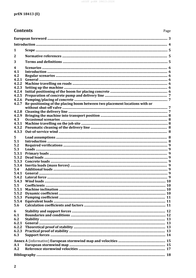
Contents Page
European foreword . 3
Introduction . 4
1 Scope . 5
2 Normative references . 5
3 Terms and definitions . 5
4 Scenarios . 6
4.1 Introduction . 6
4.2 Regular scenarios . 6
4.2.1 General . 6
4.2.2 Machine travelling on roads . 6
4.2.3 Setting up the machine . 6
4.2.4 Initial positioning of the boom for placing concrete . 6
4.2.5 Preparation of concrete pump and delivery line . 7
4.2.6 Pumping/placing of concrete . 7
4.2.7 Re-positioning of the placing boom between two placement locations with or
without shut-off valve . 7
4.2.8 Cleaning the delivery line . 7
4.2.9 Bringing the machine into transport position . 8
4.3 Occasional scenarios . 8
4.3.1 Machine travelling on the job site . 8
4.3.2 Pneumatic cleaning of the delivery line . 8
4.3.3 Out-of-service wind . 8
5 Load assumptions . 8
5.1 Introduction . 8
5.2 Required verifications . 9
5.3 Loads . 9
5.3.1 Primary loads . 9
5.3.2 Dead loads . 9
5.3.3 Concrete loads . 9
5.3.4 Inertia loads (mass forces) . 9
5.4 Additional loads . 9
5.4.1 General . 9
5.4.2 Lateral force . 9
5.4.3 Wind loads . 10
5.5 Coefficients . 10
5.5.1 Machine inclination . 10
5.5.2 Dynamic coefficient . 10
5.5.3 Pumping coefficient . 11
5.5.4 Equivalent loads . 11
5.6 Calculation coefficients and factors . 11
6 Stability and support forces . 12
6.1 Boundaries and conditions . 12
6.2 Stability . 13
6.2.1 General . 13
6.2.2 Theoretical proof of stability . 13
6.2.3 Practical proof of stability . 13
6.3 Support forces . 14
Annex A (informative) European stormwind map and velocities . 15
A.1 European stormwind map . 15
A.2 Reference stormwind velocities . 17
Bibliography . 18
European foreword
This document (prEN 18413:2026) has been prepared by Technical Committee CEN/TC 151
"Construction equipment and building material machines - Safety", the secretariat of which is held by
DIN.
This document is currently submitted to the CEN Enquiry.
Introduction
This document is a type-C standard as stated in EN ISO 12100:2010 [1].
This document is of relevance, in particular, for the following stakeholder groups representing the
market players with regard to machinery safety:
— machine manufacturers (small, medium and large enterprises);
— health and safety bodies (regulators, accident prevention organizations, market surveillance, etc.).
Others can be affected by the level of machinery safety achieved with the means of the document by the
above-mentioned stakeholder groups:
— machine users/employers (small, medium and large enterprises);
— machine users/employees (e.g. trade unions, organizations for people with special needs);
— service providers, e.g. for maintenance (small, medium and large enterprises);
— consumers (in case of machinery intended for use by consumers).
The above-mentioned stakeholder groups have been given the possibility to participate in the drafting
process of this document.
The machinery concerned and the extent to which hazards, hazardous situations or hazardous events
are covered are indicated in the Scope of this document.
When requirements of this type-C standard are different from those which are stated in type-A or type-
B standards, the requirements of this type-C standard take precedence over the requirements of the
other standards for machines that have been designed and built according to the requirements of this
type-C standard.
1 Scope
This document définés load assumptions and vérificàtions for the design of load-bearing structures of
mobile concrete pumps with placing boom and stationary placing booms.
2 Normative references
The following documents are referred to in the text in such a way that some or all of their content
constitutes requirements of this document. For dated references, only the edition cited applies. For
undated references, the latest edition of the referenced document (including any amendments) applies.
EN 12001:2012, Conveying, spraying and placing machines for concrete and mortar - Safety requirements
EN 13001-2:2021, Crane safety - General design - Part 2: Load actions
3 Terms and definitions
For the purposes of this document, the terms and définitions given in EN 12001:2012 and the following
apply.
• ISO Online browsing platform: available at http://www.iso.org/obp
• IEC Electropedia: available at http://www.electropedia.org/
3.1
boom tip
last coupling permanently connected to the last part of the placing boom
3.2
boom tip load
weight of all free-hanging components (e.g. last swivelling elbow, shut-off valve, end hose, coupling and
safety elements) and contained concrete acting at the boom tip (3.1)
3.3
intended motion range of the placing boom
space which can be covered by all geometrically possible concrete-placing boom segments
configuràtions allowed by the manufacturer rotated 360° around the vertical slewing axis of the boom
foreseen by the manufacturer
3.4
drives
structural units with the primary task to alter the position of the machine or the individual components
by acceleration, steady movement or deceleration
3.5
tilting edges
imaginary lines connecting the centres of the supports at the level of contact with the ground
3.6
pump operation
operating phase of the machine when concrete is pumped through the placing boom
Note 1 to entry: During the pump operation, the machine rests on its supporting structure, the pumping unit
including hopper and the delivery line are partially or completely filléd with concrete.
3.7
in-service wind
load that acts on the machine whenever the machine is being used for its intended primary function
Note 1 to entry: The intended primary function of a mobile concrete pump with placing boom stationary placing
boom is pump operation.
3.8
out-of-service wind (boom is not in operation)
load that acts on the machine whenever the machine is not being used for its intended primary function
4 Scenarios
4.1 Introduction
The scenarios are clàssifiéd as regular and occasional, depending on their frequency of occurrence.
The combination of the scenarios described below with load assumptions result in design-relevant load
cases (see Clause 5).
NOTE The list of the scenarios does not claim to be complete; the manufacturer can consider additional
scenarios. Not all scenarios are applicable for all types of machines, e.g. mobile concrete pumps with placing boom
versus stationary placing booms.
4.2 Regular scenarios
4.2.1 General
The regular scenarios describe typical uses of a mobile concrete pump with a placing boom and
stationary placing booms.
NOTE For a mobile concrete pump with placing boom, see Figure A.1, a) and b) of EN 12001:2012 [2]. For a
stationary placing boom, see Figure A.2 of EN 12001:2012 [2].
4.2.2 Machine travelling on roads
The machine is driven on consolidated roads at variable speeds in different directions. Support system
and placing boom are completely retracted. There is no concrete in the hopper, concrete pump, delivery
line and end hose. The concrete pump is not operated.
4.2.3 Setting up the machine
Support system and placing boom are completely retracted. The inclination of the machine corresponds
to the road gradient. There is no concrete in the hopper, concrete pump, delivery line nor end hose. The
concrete pump is not operated.
The outriggers are moved up to maximum permitted speed insofar as the drives allow until they are
deployed to a valid setup. The machine is fully lifted from the ground and is levelled with a permitted
inclination. All outriggers have ground contact. The boom is ready to be operated.
4.2.4 Initial positioning of the boom for placing concrete
The machine has been set up. The concrete pump and the delivery line contain no concrete. The concrete
pump is not operated. The hopper contains no concrete. The end hose contains no concrete, it is not
manually guided.
The placing boom is unfolded by moving its hinges and slewing gear. The placing boom is moved in
horizontal and vertical direction within the intended motion range up to maximum permitted speed as
far as the drives allow.
4.2.5 Preparation of concrete pump and delivery line
The machine has been set up and the boom initially positioned.
Initial pumping to lubricate the delivery line is performed with concrete or different material (e.g.
primer) to avoid blockages. The hopper is filléd between its maximum capacity and a minimum level
required for pump operation. The concrete pump is operated slowly with a significàntly reduced output
until the concrete or different material (e.g. primer) exits the end hose. The concrete pump contains the
maximum capacity of concrete considering a pump-spécific filling degree.
4.2.6 Pumping/placing of concrete
The machine stands on its support in accordance with the manufacturer's spécificàtions. At least three
support points are in contact with the ground. The inclination in any direction does not exceed the
permissible value in accordance with 5.4.1. The in-service wind acts gustily on the machine. The placing
boom can be in any position within its operating range, depending on the support configuràtion. The
placing boom can be fully extended. The concrete pump and the delivery line up to the boom tip (3.1)
can be full of concrete, the concrete pump exerts abrupt excitations on the placing boom, depending on
the conveying principle. The hopper filling level hovers between the définéd maximum and the
minimum required for pump operation (3.6). The concrete-pump filling is derived from the maximum
volume technically possible with due consideration for a design-dependent filling degree. The concrete
flows through the end hose unobstructed. The placing boom is moved in a horizontal and vertical
direction in such a manner that the end hose can be guided manually. The vertical movement direction
results from the placing process.
4.2.7 Re-positioning of the placing boom between two placement locations with or without
shut
...