

oSIST prEN 9300-230:2026
(Main)Aerospace series - LOTAR - LOng Term Archiving and Retrieval of digital technical product documentation such as 3D, CAD and PDM data - Part 230: As-built/As-delivered/As-maintained
- Abstract
This document specifies the “as-built” data used for demonstrating completion of the build process and conformity of the product to type design. This document defines the minimum set of information to be archived to serve as a complete representation of an organization’s as-built data.
- Status
- Not Published
- Public Enquiry End Date
- 19-Oct-2026
- Technical Committee
- I13 - Imaginarni 13
- Current Stage
- 4020 - Public enquire (PE) (Adopted Project)
- Start Date
- 14-Aug-2026
- Due Date
- 01-Jan-2027

oSIST prEN 9300-230:2026 is the Slovene publication of the draft European Standard prEN 9300-230 for the aerospace LOTAR family, prepared by ASD-STAN for CEN. It specifies the minimum as-built information to archive so an organization can demonstrate completion of the build process and conformity of the product to type design.
What does oSIST prEN 9300-230:2026 specify?
oSIST prEN 9300-230:2026 specifies the “as-built” data to retain for proving that build work is complete and that the product conforms to its type design. The document also frames how that as-built baseline relates to as-maintained data and to change-controlled product information over the life of the product.
The document is organized into Clauses 1 to 14, followed by one informative annex and a bibliography. Clause 4 explains the diagram style, Clauses 5 to 6 cover management and organization data, Clauses 7 to 10 cover build, as-built, maintenance, and change management, and Clauses 11 to 14 cover documents, access security, option effectivity, and effectivity.
| Annex | What it covers |
|---|---|
| Annex A (informative) | Metadata for archive packages, including how archive-package metadata maps to AIP structure and which fields are mandatory or recommended |
What are the key requirements of oSIST prEN 9300-230:2026?
The document uses a simple graph model for archived product data
oSIST prEN 9300-230:2026 models archive content as nodes/items and edges/connections, with minimum attributes for each. In practice, that means the archive needs enough structure to identify each item, its revision, its approval status, and its links to related items.
Clause 4 limits item attributes to essentials such as type, name, revision, ID, timestamps, ownership, status, and description. For connections, it keeps the IDs of the related items, the connection type, and change-management effectivity information. This matters because archived product data must still be searchable and traceable long after the original system changes.
Clause 4.3 adds the property sheet concept for custom or system-specific data. That lets organizations keep extra attributes, restricted data, or value-added data without forcing every PLM system into the same fixed model.
Clause 4.4 treats change as “lossless”: nothing is deleted, every change is auditable, and past states can be queried. For a reader, that means the archive is meant to support reconstruction of what was current, pending, or historical at any point in time.
Clauses 5 to 8 define the build baseline and its evidence
oSIST prEN 9300-230:2026 requires management information for people, companies, roles, contracts, build items, and build plans. These links matter because build evidence is not only technical data - it also needs traceability to who did the work, for whom, and under what business relationship.
Clause 7 defines the as-built baseline as the data unique to completed build and test activity, plus the engineering data applicable to each unit. It also says the build record includes completed work instructions, non-conformance records, test results, and inspection records. In practice, that is the evidence used to show the physical unit matches the released definition.
Clauses 8.2 and 8.3 extend this to product-level and unit-level recording. They cover product configuration, instance of product, installation/assembly/part, serial number assigned during build, life cycle data, production measurements, planned measurements, and realization links from design to the built item. That lets an archive answer basic questions such as which serial-numbered unit was built, what was measured on it, and which design definition it realized.
Clauses 8.4 to 8.6 handle as-built non-conformance records. The document captures accepted non-conformance dispositions, authorized substitutions, and performance limitations that result from the disposition. This matters when a built unit differs from the nominal design but is still accepted for use with controlled limitations.
Clauses 8.7 to 8.9 describe breakdowns, including manufacturing breakdowns, process plans, operations, build records, inputs, outputs, resources, and sequence. For an engineer or quality manager, this is the structure needed to connect the manufacturing route to the completed build evidence.
Clauses 9 and 10 extend traceability into service and change control
oSIST prEN 9300-230:2026 adds an as-maintained view in Clause 9. That includes in-service activity, life cycle records, maintenance operations, approved modification design, maintenance records, modification installation, and the related process plan and records. In practice, this is the service history needed to track what happened after delivery, including service bulletins, retrofit work, and maintenance-driven changes.
Clause 10 models change management between design, build plan, and in-service activity. It shows how a design change can revise the build plan and define where a manufacturing incorporation point applies. This supports controlled introduction of changes across production and support activities.
Clauses 11 to 14 add document control, security, options, and effectivity
Clause 11 links parts to documents and document revisions. Clause 12 adds access security through licenses and classification, so the archive can carry restrictions and access rules. Clauses 13 and 14 handle option effectivity and effectivity, including customer-selected options, dates, lots, serial numbers, tail numbers, and product or plant context. In practice, these clauses are what let a user resolve the correct configuration for a specific unit, customer order, plant, or change cut-in point.
What terms does oSIST prEN 9300-230:2026 define?
- LOTAR - LOng Term Archiving and Retrieval, the aerospace standard family for long-term preservation and retrieval of technical product documentation.
- PLM - product lifecycle management, the system context used to manage product, build, maintenance, and change data.
- AIP - archive information package, the archival package structure referenced in Annex A.
- As-built baseline - the manufactured-item build record baseline at the end of the manufacturing cycle.
- As-maintained view - the record of modifications occurring after the As-Delivered stage until end of life.
- Property sheet - a container for custom or PLM system-specific attributes attached to an item or connection.
- Effectivity - the date, unit, lot, serial, tail-number, or option condition that determines when a change applies.
Who uses oSIST prEN 9300-230:2026?
oSIST prEN 9300-230:2026 is used in aerospace product-data and PLM environments where build, maintenance, and change records must be archived and later retrieved. It is relevant to manufacturers, configuration management teams, quality and inspection functions, maintenance organizations, and archive administrators.
The use cases in the introduction show why it matters in practice: certification evidence, product liability, acquisition or divestiture transfers, delivery of type design data to customers, retrieval of build and maintenance records, non-conformance handling, and modification or spares work. It also fits organizations that need to track ownership transfer, service bulletins, retrofit actions, and maintenance-driven changes.
Which standards are used with oSIST prEN 9300-230:2026?
The document cites these companion standards and references:
- EN 9300-021 - provides metadata for archive packages and PLM-specific metadata for AIP integration.
- EN 9300-200 - gives the general concepts for LOTAR product-structure archiving.
- EN 9300-205 - provides the validation property method used for archived data.
- EN 9300-210 - supplies the as-designed baseline that Part 230 expands.
- EN 9300-240 - covers product management data in an in-development view.
- EN 9300-250 - covers change documentation.
- ISO 10303-203 and ISO 10303-242 - provide product-data exchange application protocols used as background for the model.
- ISO/TS 10303-4000 - provides the core model referenced by the P4000 mappings.
- FAA aviation safety: AC 20-176 - is cited for service-bulletin context.
What does the oSIST prEN 9300-230:2026 document contain?
The document contains diagram-based descriptions of management information, organization, product build process, as-built recording, non-conformance handling, breakdowns, as-maintained data, change management, documents, access security, option effectivity, and effectivity. These are presented through figures and tables that map each node/item and edge/connection to P4000 concepts.
It also includes an informative Annex A that maps archive-package metadata to AIP structure and marks fields as mandatory or recommended. The bibliography ties the part to the related LOTAR, ISO 10303, and FAA references used in the surrounding framework.
Get Certified
Connect with accredited certification bodies for this standard

BSI Group
BSI (British Standards Institution) is the business standards company that helps organizations make excellence a habit.

Bureau Veritas
Bureau Veritas is a world leader in laboratory testing, inspection and certification services.

DNV
DNV is an independent assurance and risk management provider.
Sponsored listings
Frequently Asked Questions
oSIST prEN 9300-230:2026 is a draft published by the Slovenian Institute for Standardization (SIST). Its full title is "Aerospace series - LOTAR - LOng Term Archiving and Retrieval of digital technical product documentation such as 3D, CAD and PDM data - Part 230: As-built/As-delivered/As-maintained". This standard covers: This document specifies the “as-built” data used for demonstrating completion of the build process and conformity of the product to type design. This document defines the minimum set of information to be archived to serve as a complete representation of an organization’s as-built data.
This document specifies the “as-built” data used for demonstrating completion of the build process and conformity of the product to type design. This document defines the minimum set of information to be archived to serve as a complete representation of an organization’s as-built data.
oSIST prEN 9300-230:2026 is classified under the following ICS (International Classification for Standards) categories: 01.110 - Technical product documentation; 35.240.30 - IT applications in information, documentation and publishing; 49.020 - Aircraft and space vehicles in general. The ICS classification helps identify the subject area and facilitates finding related standards.
oSIST prEN 9300-230:2026 is available in PDF format for immediate download after purchase. The document can be added to your cart and obtained through the secure checkout process. Digital delivery ensures instant access to the complete standard document.
Standards Content (Sample)
SLOVENSKI STANDARD
01-oktober-2026
Aeronavtika - LOTAR - Dolgoročno arhiviranje in iskanje digitalne tehnične
dokumentacije o izdelkih, kot so podatki o 3D, CAD in PDM - 230. del: Kot
zgrajeno/Kot dostavljeno/Kot vzdrževano
Aerospace series - LOTAR - LOng Term Archiving and Retrieval of digital technical
product documentation such as 3D, CAD and PDM data - Part 230: As-built/As-
delivered/As-maintained
Luft- und Raumfahrt - LOTAR - Langzeit-Archivierung und -Bereitstellung digitaler
technischer Produktdokumentationen, wie zum Beispiel von 3D-, CAD- und PDM-Daten -
Teil 230: Wie gebaut/geliefert/instandgehalten
Ta slovenski standard je istoveten z: prEN 9300-230
ICS:
01.110 Tehnična dokumentacija za Technical product
izdelke documentation
35.240.30 Uporabniške rešitve IT v IT applications in information,
informatiki, dokumentiranju in documentation and
založništvu publishing
49.020 Letala in vesoljska vozila na Aircraft and space vehicles in
splošno general
2003-01.Slovenski inštitut za standardizacijo. Razmnoževanje celote ali delov tega standarda ni dovoljeno.
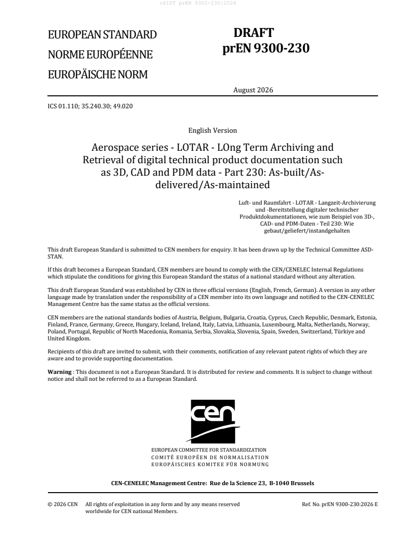
DRAFT
EUROPEAN STANDARD
NORME EUROPÉENNE
EUROPÄISCHE NORM
August 2026
ICS 01.110; 35.240.30; 49.020
English Version
Aerospace series - LOTAR - LOng Term Archiving and
Retrieval of digital technical product documentation such
as 3D, CAD and PDM data - Part 230: As-built/As-
delivered/As-maintained
Luft- und Raumfahrt - LOTAR - Langzeit-Archivierung
und -Bereitstellung digitaler technischer
Produktdokumentationen, wie zum Beispiel von 3D-,
CAD- und PDM-Daten - Teil 230: Wie
gebaut/geliefert/instandgehalten
This draft European Standard is submitted to CEN members for enquiry. It has been drawn up by the Technical Committee ASD-
STAN.
If this draft becomes a European Standard, CEN members are bound to comply with the CEN/CENELEC Internal Regulations
which stipulate the conditions for giving this European Standard the status of a national standard without any alteration.
This draft European Standard was established by CEN in three official versions (English, French, German). A version in any other
language made by translation under the responsibility of a CEN member into its own language and notified to the CEN-CENELEC
Management Centre has the same status as the official versions.
CEN members are the national standards bodies of Austria, Belgium, Bulgaria, Croatia, Cyprus, Czech Republic, Denmark, Estonia,
Finland, France, Germany, Greece, Hungary, Iceland, Ireland, Italy, Latvia, Lithuania, Luxembourg, Malta, Netherlands, Norway,
Poland, Portugal, Republic of North Macedonia, Romania, Serbia, Slovakia, Slovenia, Spain, Sweden, Switzerland, Türkiye and
United Kingdom.
Recipients of this draft are invited to submit, with their comments, notification of any relevant patent rights of which they are
aware and to provide supporting documentation.
Warning : This document is not a European Standard. It is distributed for review and comments. It is subject to change without
notice and shall not be referred to as a European Standard.
EUROPEAN COMMITTEE FOR STANDARDIZATION
COMITÉ EUROPÉEN DE NORMALISATION
EUROPÄISCHES KOMITEE FÜR NORMUNG
CEN-CENELEC Management Centre: Rue de la Science 23, B-1040 Brussels
© 2026 CEN All rights of exploitation in any form and by any means reserved Ref. No. prEN 9300-230:2026 E
worldwide for CEN national Members.
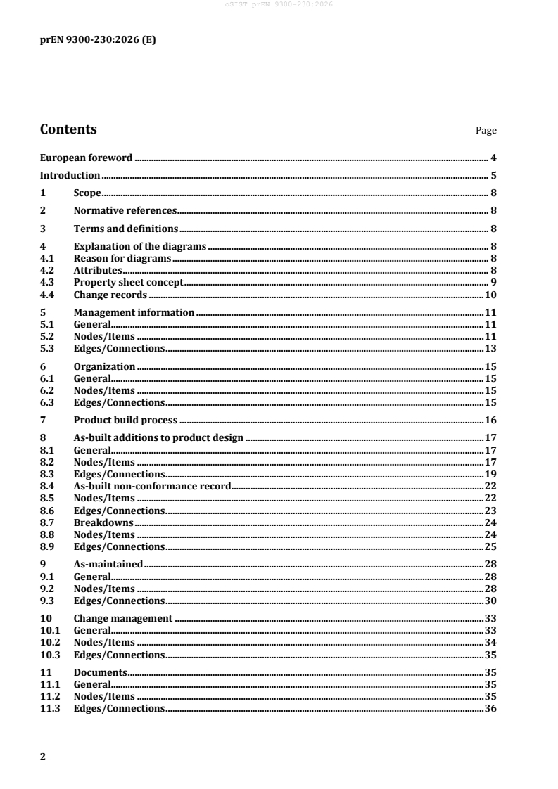
Contents Page
European foreword . 4
Introduction . 5
1 Scope . 8
2 Normative references . 8
3 Terms and definitions . 8
4 Explanation of the diagrams . 8
4.1 Reason for diagrams . 8
4.2 Attributes . 8
4.3 Property sheet concept . 9
4.4 Change records . 10
5 Management information . 11
5.1 General. 11
5.2 Nodes/Items . 11
5.3 Edges/Connections . 13
6 Organization . 15
6.1 General. 15
6.2 Nodes/Items . 15
6.3 Edges/Connections . 15
7 Product build process . 16
8 As-built additions to product design . 17
8.1 General. 17
8.2 Nodes/Items . 17
8.3 Edges/Connections . 19
8.4 As-built non-conformance record . 22
8.5 Nodes/Items . 22
8.6 Edges/Connections . 23
8.7 Breakdowns . 24
8.8 Nodes/Items . 24
8.9 Edges/Connections . 25
9 As-maintained . 28
9.1 General. 28
9.2 Nodes/Items . 28
9.3 Edges/Connections . 30
10 Change management . 33
10.1 General. 33
10.2 Nodes/Items . 34
10.3 Edges/Connections . 35
11 Documents . 35
11.1 General. 35
11.2 Nodes/Items . 35
11.3 Edges/Connections . 36
12 Access security . 36
12.1 General . 36
12.2 Nodes/Items . 37
12.3 Edges/Connections . 37
13 Option effectivity . 38
13.1 General . 38
13.2 Option effectivity definitions. 39
13.3 Option effectivity managing change . 39
13.4 Diagram . 40
13.5 Nodes/Items . 40
13.6 Edges/Connections . 41
14 Effectivity . 42
Annex A (informative) Metadata for archive packages. 45
Bibliography . 49
European foreword
This document (prEN 9300-230:2026) has been prepared by ASD-STAN.
After enquiries and votes carried out in accordance with the rules of this Association, this document has
received the approval of the National Associations and the Official Services of the member countries of
ASD-STAN, prior to its presentation to CEN.
This document is currently submitted to the CEN Enquiry.
The EN 9300-200 family of standards, under the general title Aerospace series — LOTAR — LOng Term
Archiving and Retrieval of digital technical product documentation such as 3D, CAD and PDM data,
consists of the following parts:
— Part 200: Common Concepts for LOng Term Archiving and Retrieval of Product Structure Information
— Part 205: Product structure validation
— Part 210: Product management data in an “as designed” view
— Part 230: As-built/As-delivered/As-maintained
— Part 240: Product Management Data “in-development” (including preliminary design review, critical
design review, FAI, etc.)
— Part 250: Change documentation
Introduction
All information represented in this document (e.g. diagrams) is archived. The overall general
description of the archival of product lifecycle management data is in EN 9300-200. The validation
property method applied to this archived data is in EN 9300-205. The scenarios and use cases used to
support EN 9300-230 include:
— S1 – Evidence of the baseline for verification, certification, or product liability:
— UC1.1 – Long term archiving of type design configuration (certification);
— UC1.2 – Acquisition/divestiture resulting in transfer of product definition data and type design
data;
— UC1.3 – Verification of design compliance to requirements;
— UC1.4 – Ability to retrieve the build, conformance, and maintenance records for a detail,
assembly, or installation;
— UC1.5 – To support delivery of type design configuration data to a customer;
— UC1.6 – Transfer of ownership;
— UC1.8 – To support data used to address non-conforming conditions (e.g. if different than
design);
— S2 – Reuse of design data as a starting baseline for design changes:
— UC2.1 – Changes to product definition data resulting in a major or minor change to the type
design data;
— UC2.2 – To support the modification of existing product (e.g. for spares purposes).
This document does not apply to the creation of an OAIS/LOTAR information package. Nor does it
address common issues in the archive domain, such as snapshot vs. incremental archival methods
(which are determined as part of the implementation of an archive system), or package-to-package
linkages, or how to identify proper metadata for an archival package. For integration of PLM metadata
with other domain and common metadata, see EN 9300-021.
This document serves as the as-built baseline. In some cases, the as-planned baseline is derived from
the resolved design product structure. In other cases, the as-planned baseline equals the engineering
baseline, and changes to the build sequence are incorporated in engineering.
This document describes the expansion of EN 9300-210 on the as-designed baseline to include as-built
records which are the results of completing the work defined in an as-planned baseline, including
variances; and reflect the build configuration of individual units.
This document also includes the application of PLM-specific metadata (see EN 9300-021) and definition
of PLM-specific metadata for archive information packages (AIP).
UC1.7 is a use case specific to EN 9300-210 (Change to Design) and does not apply to this document.
Visually, these areas can be depicted as in Figure 1.
Figure 1 —As-designed and as-built data
Figure 2 — As-built/as-maintained concepts
The “As-Built” view represents the manufactured items build record baseline at the end of the
manufacturing cycle, for more details see Figure 2.
The “As-Maintained” view represents all modification occurring after the “As-Delivered” stage and
until end of life of the product.
E.g. application of service bulletin, retrofit or airlines maintenance activities and modifications.
1 Scope
This document specifies the “as-built” data used for demonstrating completion of the build process and
conformity of the product to type design. This document defines the minimum set of information to be
archived to serve as a complete representation of an organization’s as-built data.
2 Normative references
There are no normative references in this document.
3 Terms and definitions
No terms and definitions are listed in this document.
ISO and IEC maintain terminology databases for use in standardization at the following addresses:
— ISO Online browsing platform: available at https://www.iso.org/obp/
— IEC Electropedia: available at https://www.electropedia.org/
4 Explanation of the diagrams
4.1 Reason for diagrams
There is a diversity of product lifecycle management (PLM) systems among LOTAR members. This
diversity reflects the differences in terms and processes used to manage the products. While the
members are subject matter experts (SME) in the use of PLM systems, none of them are conversant
with formal modelling methods as used by the STEP community. A simple diagramming technique is
used to supplement the textual content that is easy to understand and can be created with presentation
or drawing tools. The diagrams are based on graph theory and employ only two constructs: nodes and
edges. In the usage, the terms items and connections are typically used for edges and nodes,
respectively. The term “item” is a generic term for the object being represented (e.g. design item can be
a CAD file, part, assembly). Edges (connections) are directional, generally representing the connection
in natural language. This graph form is known as a “directed property graph”, for example “has part”. A
connection has “subject” side, which is called the “from” side, and an “object” side, which is called the
“to” side. The diagrams omit cardinality information in the interest of simplicity, believing that
cardinality can easily be added once formal STEP models are developed. Edges represented with dashed
lines correspond to data flow and not additional relationships in the data model.
Individual diagrams are simplified so that they focus on their particular subject and do not show all
potential relationships.
NOTE 1 In order to keep the diagrams concise, a variant of graph theory called hypergraph theory is used,
where edges are permitted to connect to other edges (but not multiple nodes to multiple nodes).
NOTE 2 Not all elements defined in EN 9300-210 are represented in the EN 9300-230 diagrams. See
EN 9300-210 for context.
4.2 Attributes
All nodes and edges (items and connections) have attributes. PLM systems are designed to be
customized. Therefore, it focuses on the minimum attribution.
The minimum attribution for an item is generally:
— type: the kind of thing the item represents. For example, a person, a part, a product, a document;
— name: the name used for human readable consumption;
— revision: the revision of the item as it undergoes changes;
— ID: the internal identity of the item that is unique;
NOTE Typically, the triplet (type, name, revision) is also unique in a PLM system.
— timestamps: creation and modification;
— references to persons or systems acting as creator, modifier, and “owner”;
— status of item: especially whether it is (was) approved;
— description: an item often has a description, such as a title for a drawing item, or nomenclature for a
part item.
The minimum attribution for a connection is:
— the ID of the connection itself;
— the type of the connection itself;
— the ID of the FROM item;
— the ID of the TO item;
— the change management effectivity timestamps:
— start: the date the connection was approved for use;
— stop: the date the connection was deprecated for use;
— the change management effectivity authorizations:
— start authority: reference to the change document approving this connection;
— stop authority: reference to the change document deprecating this connection;
— timestamps: creation and modification;
— references to persons or systems acting as creator, modifier, and “owner”.
4.3 Property sheet concept
Since these minimum attributes are not sufficient, the notion of a “property sheet” is used which is a
container for the custom or PLM system-specific data that is needed. The name “property sheet” is
intended to convey a simple enumeration of attribute names, values, datatypes (string, Boolean,
number, date, etc.), and unit of measure. Such a set of properties could be modelled in diagrams as a
node with an edge named “has property” connecting it to the item or connection having the properties.
But that needlessly complicates the diagrams, since virtually any item or connection have custom
properties. The property sheet concept can also be used to achieve other goals of a PLM system:
— Ad hoc properties: In this case, an item or connection might have multiple sets of properties. The
extra properties might provide attributes for a part that are unique to its part family. For example, a
bolt might additional attributes of head type, length, etc.; whereas a nut can have inner and outer
diameter, lock nut indicator, etc.
— Restricted properties: In this case, properties might be segregated when the values may be export
controlled or are proprietary information.
— Value added properties: during the lifecycle of the part, extra attributes, such as supplier, cost, plant,
etc. might be added by downstream business functions.
Figure 3 shows a visual depiction of the property sheet concept.
Figure 3 — Property sheet concept
A property sheet can be viewed a special kind of item with a type indicating the sort of properties it
contains. Since most systems do not actually model properties this way, the revisions of its base item
type and the properties can be synced, along with connections to change items.
4.4 Change records
In general, PLM systems can be concisely characterized by having “lossless change methods”. This term
captures the following concepts:
— Nothing is ever deleted.
— Every change is auditable (why, who, what, and when).
— Possibility to query the state of the PLM system at any time in the past and see:
— what was current and approved at that time;
— what was proposed or pending at that time;
— what was historical at that time.
In the following clauses, statements to the effect that these objects are subject to change control are
provided, but the above bullets points hint that change is a fundamental aspect to PLM and shall
permeate all aspects of product data (see Clause 10).
5 Management information
5.1 General
Diagrams for management information are illustrated in Figure 4. Table 1 and Table 2 show an
overview as well.
Figure 4 — Management information diagram
5.2 Nodes/Items
The nodes and items of management information can be in accordance with Table 1.
Table 1 — Management information nodes/items
Name Description Notes STEP Relationship
Company The legal entity of the Generally, the nationality P4000, “Organization”
company. or country of
incorporation is key
information for access
security.
Name Description Notes STEP Relationship
Person Represents a person In some countries the P4000, “Person”
who has approved, place of birth is required
performed work, etc. for access security. All
requiring certain require the citizenship for
information about the access security (for
person to be retained. national export control
regulations).
Company The identifier of the This is generally P4000, “Organization.Id”
Identifier/ legal entity where work represented by a DUNS,
Location was performed. CAGE code, etc. and
includes street address
and other contact
information. Sometimes a
DUNS number is also used.
Role Represents the role of For example: author, P4000,
the person having engineer, checker, etc. “PersonOrganizationAssignment.Role”
responsibility of a
design or build item.
Contract A business Contracts may concern the P4000, “Contract”
arrangement for the design of part version
supply of goods or objects, the delivery of
services. drawing objects, or the
execution of activity
objects.
This represents This could be either an
Design Item P4000, e.g. “Part”, “Document”
something in the Type item that represents a
Design that can be thing (like a drawing) or a
owned and changed. connection (like “has
part”).
Build Item This represents an item This represents a thing – a P4000, “IndividualPart”
that is built to conform (physical or software)
to all or a portion of a part, assembly, or
design item installation.
configuration.
Build Plan/ This represents a — P4000, “ProcessPlan” /
Operation manufacturing step “ProcessOperationOccurrence”
which uses all or part of
engineering definition
to define the work for a
detail, assembly, or
installation build task.
5.3 Edges/Connections
The edges and connections of management information can be in accordance with Table 2.
Table 2 — Management information edges/connections
Name Description Notes STEP Relationship
Has Company — From: Company Laws governing this P4000, “OrganizationRelationship”
relationship vary
— To: Company
from country to
Indicates a legal
country.
subsidiary relationship.
Has Business — From: Company Such relationships P4000, “OrganizationRelationship”
Relationship always have non-
— To: Company
disclosure or
Indicates a partnership,
proprietary
supplier, etc. relationship
information
between two legal
agreements which
entities.
may be used in
access security. In
some cases, there
are contracts
between the
companies.
Has Company
— From: Company — P4000, “Organization.Id”
Identifier
— To: Company
Identifier
Indicates the locations of
a company or legal entity.
Is Employer — From: Company The nationality of P4000, “PersonInOrganization”
Of the company may be
— To: Person
used in access
Indicates
security; perhaps
employer/employee
overriding
relationship.
nationality of the
person.
Is Manager Of — From: Person This may be used to P4000,
certain approvals “PersonInOrganizationRelationship”
— To: Person
where one-over-one
Indicates supervisory
signoffs are
relationship.
required.
Has — From: Person — P4000, “PersonOrganizationAssignment”
Responsibility
— To: a Design Item
Indicates responsible
persons in a design
activity.
Has — From: Person — P4000, “PersonOrganizationAssignment”
Responsibility
— To: a Build Item
Indicates responsible
persons in a build
activity.
Name Description Notes STEP Relationship
Has Role — From: Role — P4000,
“PersonOrganizationAssignment.Role”
— To: “Has
Responsibility”
Indicate the role of the
person in the
design/build activity.
Has Location — From: Person — P4000, “AddressAssignment”
— To: Location
Indicates the physical
work location of the
person (employee).
Is Original — From: Location This value is never P4000, “PersonOrganizationAssignment”
Design altered, even when
— To: a Design Item
Activity the ownership of the
Indicates who created
design item is sold
the design item
or transferred.
originally.
Is Build — From: Location This value is never P4000, “PersonOrganizationAssignment”
Activity altered, even when
— To: a Design Item
the ownership of the
Indicates who created
design item is sold
the design item
or transferred.
originally.
Is Transferred — From: Location — P4000, “PersonOrganizationAssignment”
Design
— To: a Design Item
Activity
Indicates the current
owner of a design item if
it has been sold or
transferred.
Is Transferred — From: Location — P4000, “PersonOrganizationAssignment”
or Multi-
— To: a Build Item
Sourced Build
Indicates the current
Activity
owner of a build item if it
has been sold or
transferred.
Includes — From: Build Item — P4000,
Consumes … “ProcessOperationResourceAssignment”
— To: a Design Item
T.B.D.
Has Contract — From: “Has Business — P4000, “ContractAssignment”
Relationship”
— To: Contract
Indicates the governing
documentation between
two companies.
6 Organization
6.1 General
Figure 5 shows the diagram for “organization”. Table 3 and Table 4 show an overview as well.
Figure 5 — Organization
6.2 Nodes/Items
Table 3 specifies the description and further information for the “organization” node or item.
Table 3 — Organization nodes/items
Name Description Notes STEP Relationship
Organization The name of an organization May also include the P4000, “Organization”
within a company. functional responsibility of
the organization.
6.3 Edges/Connections
Table 4 specifies the description and further information for the “organization” edges or connections.
Table 4 — Organization edges/connections
Name Description Notes STEP Relationship
Has — From: Company — P4000, “OrganizationRelationship”
Organization
— To: Organization
Indicates which company has
the named organization.
Is in — From: Person — P4000, “PersonInOrganization”
Organization
— To: Organization
Indicates in which organization
a person works.
Has — From: Organization — P4000,
Responsibility “PersonOrganizationAssignment”
— To: a Design Item
Indicates which organization
owns or created a design item.
7 Product build process
Figure 6 — Product build process
The as-built baseline represents the data unique to completed build and test activity, as well as baseline
engineering data applicable to individual units (build items), and interim manufacturing configurations
derived from engineering, see Figure 6.
The product documentation includes the operation, maintenance instructions and a subset of the build
records to be delivered to the customer with the product.
The build record contains the completed work instructions, the non-conformance records, the test
results and the inspection records. The subset of the build records contains only the build records
information relevant for the maintenance of the product.
8 As-built additions to product design
8.1 General
Regarding the diagrams for product design, see Figure 7 and Figure 8. Further information is provided
in Table 5 and Table 6.
First is the focus on product (see Figure 7).
Figure 7 — As-built data recording and reporting
8.2 Nodes/Items
Table 5 specifies the description and further information for the “as-built data recording and reporting”
nodes or items.
Table 5 — As-built data recording and reporting nodes/items
Name Description Notes STEP Relationship
Product Indicates the design Includes optional or P4000, “ProductConfiguration”
configuration, which alternate configurations
includes design driven by specifications.
applicable to all units
produced to the design.
Name Description Notes STEP Relationship
Instance of Indicates the design Selected options provide P4000, “IndividualPart”
Product configuration resolved configuration for
applicable to an an individual unit.
individual unit.
Installation, Indicates a design item These are nodes in the P4000, “PartVersion”
Assembly or (represents design product structure below
Part configurations of a the end item product.
physical installation,
assembly, or part).
Instance of Indicates a design item Physical item which P4000, “IndividualPartVersion”
Installation, applicable to a conforms to design item.
Assembly or particular unit (serial Sum of completed work
Part number, tail number, records and inspection
etc.). records constitutes
conformity of physical item
to design.
Installed Record all the — P4000, “Document”
Component information about a
Data component of a
delivered product.
Serial Number This represents the Serial numbers are P4000, “IndividualPart.Id”
Assigned unique identifier for an assigned to individual
During Build individual detail, parts.
assembly, or
NOTE Lot numbers
installation usually
are assigned to a group of
assigned during
parts produced as a set
manufacturing.
during manufacturing.
Batch numbers generally
are used to identify a
quantity of raw material
produced as the output of
particular manufacturing
sequence. Lot and batch
numbers are not depicted
in the diagram.
Life Cycle Data Indicates the state of E.g.: number of cycles P4000, “IndividualPartView”-
the physical part sustained by the physical > “PropertyValue”
(e.g. represents the part.
cycle of maintenance of
the physical part).
Production Represents the — P4000, “MeasuredCharacteristic”
Measurements measure realized on
the manufactured item.
Planned Represents how to Planned measurements are
P4000, “PlannedCharacteristic”
Measurements measure the the requirements coming
requirements to be from the as designed and
realized on the the requirements from the
manufactured item. as planned (e.g. process
control document for
different manufacturers of
the same component, .).
Name Description Notes STEP Relationship
Instance of Represents the usage of — P4000,
Installation a realized installation, “IndividualAssemblyRelationship”
Usage assembly, or part.
8.3 Edges/Connections
Table 6 specifies the description and further information for the “as-built data recording and reporting”
edges or connections.
Table 6 — As-built data recording and reporting edges/connections
Name Description Notes STEP Relationship
Has Realization — From: Product — P4000,
“PartVersionToIndividualPartVersionAssociation”
— To: Instance of
Product
Represents a
manufactured unit of
a product.
— From: Installation,
Assembly, Part
— To: Instance of
Installation,
Assembly, Part
Represents a
component included
in an instance of a
product.
Has Design — From: Product — P4000, “ProductDesignAssociation”
Configuration
— To: Installation,
Assembly or Part
Represents a defined
configuration for a
product design.
Has Build — From: Instance of — P4000, “IndividualPartVersionRelationship”
Configuration Product
— To: Instance of
Installation, Assembly
or Part
Represents a resolved
configuration for a
product.
Has S/N — From: Instance of — P4000, “IndividualPart.Id”
Installation, Assembly
or Part
— To: Serial Number
Assigned During Build
Represents the
assignment of a serial
number to a
manufactured
product.
Name Description Notes STEP Relationship
Has Usage — From: Instance of — P4000,
Installation Usage “IndividualAssemblyRelationship.Relating”
— To: Instance of
Installation, Assembly
or Part
— From: Instance of
Has Part — P4000, “IndividualAssemblyRelationship.Related”
Installation Usage
— To: Instance of
Installation, Assembly
or Part
Has Planned — From: Installation, E.g. when P4000, “RequirementAssignment”
Characteristics Assembly or Part required, the
serial
— To: Planned
number of
Measurements
the part that
— From: Instance of
is installed on
Installation Usage
a product is
— To: Planned
recorded.
Measurements
Represents the
requirement on the
recording data.
Has Recorded — From: Instance of E.g. No mapping needed
Data Installation, Assembly expiration
or Part date.
— To: Life Cycle Data
Represents the life
cycle stage data
associated to the
installed part.
Has Design — From: Instance of — P4000, “MeasuredCharacteristic.TestedPart”
Characteristics Installation, Assembly
or Part
— To: Production
Measurements
Represents the
measure to be
realized on the
installed part
according to the
requirement.
Has Recorded — From: Serial E.g. number No mapping needed
Number Assigned of take off
Data
During Build and landing
cycles before
— To: Installed
a
Component Data
maintenance.
Record the serial
number of the part
installed.
— From: Life Cycle
Data
Name Description Notes STEP Relationship
— To: Installed
Component Data
Record the life cycle
stage status of the
part installed.
Has Data — From: Installed
— No mapping needed
Reporting Component Data
Requirement
— To: Instance of
Product
Reporting the data
that has been
recorded for a
component installed
on an instance of a
product.
— From: Production
Measurements
— To: Instance of
Product
Reporting the data for
a measurement that
has been recorded for
a component installed
on an instance of a
product.
— From: Instance of
Installation Usage
— To: Installed
Component Data
Has Data — From: Data — No mapping needed
Recording Recording
Requirement Requirement
— To: Installed
Component Data
Is Defined By — From: Production — P4000,
Measurements “MeasuredCharacteristic.PlannedCharacteristic”
— To: Planned
Measurements
8.4 As-built non-conformance record
For the diagram for product design – as-built non-conformance record is as follows, see Figure 8.
Further information is provided in Table 7 and Table 8.
Figure 8 — As-built non-conformance record
8.5 Nodes/Items
Table 7 specifies the description and further information for the “as-built non-conformance record”
nodes or items.
Table 7 — As-built non-conformance record nodes/items
Name Description Notes STEP Relationship
Resolved/accepted Non-conformance E.g. a paint is P4000, “Observation” in combination with
nonconformance issue(s) accepted scratched during P4000, “WorkOrder” and
disposition or resolved with installation and “PlannedActivity”
associated actions. need to be
reapplied.
Authorized The agreement on E.g. a larger fastener P4000, “PlannedActivity” with activity
substitution the disposition to is used because the type “built part substitution”
use a part different hole is damaged and
from the one has to be redrilled.
defined by the
engineering.
Performance The agreement on E.g. the drilled hole P4000, “PlannedActivity” with activity
limitations the disposition required more type, “performance limitation”
impacts the frequent inspection
performance or during service.
maintenance of the
product.
8.6 Edges/Connections
Table 8 specifies the description and further information for the “as-built non-conformance record”
edges or connections.
Table 8 — As-built non-conformance record edges/connections
Name Description Notes STEP Relationship
Has NC — From: Instance of — P4000, “Observation”<-
Installation, Assembly or ObservationAssignment-
Part >PlannedActivity < -
ActivityAssignment (with
— To: Resolved/accepted
Role = 'input'-
non-conformance
> IndividualPartVersion
disposition
Represents a
nonconformance against
a manufactured
component and a
disposition.
Has — From: — P4000, “Observation”<-
substitution Resolved/accepted non- ObservationAssignment-
>PlannedActivity < -
conformance disposition
ActivityAssignment (with
— To: Authorized
Role = 'output'-
substitution
> IndividualPartVersion
Represents the
authorization for the non-
conformance disposition
to use a part in place of
the part called out by the
definition of the
engineering.
Has limitation — From: E.g. reduce cycle time P4000, “Observation”<-
Resolved/accepted non- between maintenance. ObservationAssignment-
conformance disposition >PlannedActivity < -
ActivityAssignment (with
— To: Performance
Role = 'output'-
limitations
> RequirementVersion
Represents any
limitations imposed as a
result of the
nonconformance
disposition.
8.7 Breakdowns
Figure 9 depicts alternative breakdowns of the product, which can be full or partial (see also Table 9
and Table 10).
Figure 9 — Breakdowns
8.8 Nodes/Items
Table 9 specifies the description and further information for the “breakdowns” nodes or items.
Table 9 — Breakdowns nodes/items
Name Description Notes STEP Relationship
Installation Indicates a design item An assembly or part and P4000, “PartVersion”
Assembly, or (represents its connections are
Part configurations of a detailed in Figure 9.
physical installation,
assembly, or part).
Instance of Indicates a design item Physical item which
P4000, “IndividualPartVersion”
Installation, applicable to a particular conforms to design item.
Assembly, or unit (serial number, tail Sum of completed work
Part number, etc.). records and inspection
records constitutes
conformity of physical
item to design.
Manufacturing Indicates an alternative Alternative views of the P4000, “BreakdownVersion”
Breakdown breakdown of the structure are common.
product structure such as Examples include: kitting,
an interim manufacturing MBOM structures, etc.
configuration. These breakdowns may
have dependent
relationships. For
example, MBOM is
dependent on or derived
from EBOM.
Name Description Notes STEP Relationship
Process Plan Manufacturing steps — P4000, “ProcessPlan”
required to produce a
product (from a
manufacturing
breakdown).
Defines the operations.
Operation An element of the Operation accounts for P4000,
manufacturing work part in the design “ProcessOperationDefinition” and
breakdown. breakdown or product “ProcessOperationOccurrence”
structure.
Build Record A record of completion of Verification stamps can P4000, “ActualActivity”
work instructions defined show that the build record
in the as-planned is complete.
baseline.
8.9 Edges/Connections
Table 10 specifies the description and further information for the “breakdowns” edges or connections.
Table 10 — Breakdowns edges/connections
Name Description Notes STEP Relationship
Has Parts — From: — P4000, “BreakdownOf”
Manufacturing
Breakdown
— To: Installation,
Assembly, or Part
Associates the
manufacturing
breakdown
...