

SIST EN 301 489-9 V2.2.1:2026
(Main)ElectroMagnetic Compatibility (EMC) standard for radio equipment and services - Part 9: Specific conditions for wireless microphones, similar Radio Frequency (RF) audio link equipment, cordless audio, in-ear monitoring and assistive listening devices - Harmonised Standards for ElectroMagnetic Compatibility
- Abstract
The present document specifies technical characteristics and methods of measurements for wireless microphones, similar RF audio link equipment, cordless audio (including low power Band II transmitters), in-ear monitoring, cochlear implant and assistive listening devices, intended for the transmission of music and speech including the associated ancillary equipment in respect of electromagnetic compatibility, as detailed in table 1. Technical specifications related to the antenna port and emissions from the enclosure port of the radio equipment are out of scope of the present document. Such technical specifications are found in the relevant product standards for the effective use of the radio spectrum, see table 1. The present document specifies the applicable test conditions, performance assessment and performance criteria for wireless microphones, similar RF audio link equipment, cordless audio, in-ear monitoring, ALD and Cochlear Implants and associated ancillary equipment. This equipment can use analogue or digital modulation techniques.
For cochlear implants more stringent EMC standards exist and Annex E provides information on its relationship to the present document.
NOTE 1: Technical specifications related to conducted emission EMC requirements below 9 kHz on the AC mains port of radio equipment are out of scope of the present document. Such technical specifications are normally found in the relevant product family standards for AC mains powered equipment (e.g. EN 61000-3-2 [i.6] and EN 61000-3-3 [i.7]).
NOTE 2: The relationship between the present document and essential requirements of article 3.1(b) of Directive 2014/53/EU [i.1] is given in Annex A.
- Status
- Published
- Public Enquiry End Date
- 31-May-2026
- Publication Date
- 04-Oct-2026
- Technical Committee
- MOC - Mobile Communications
- Current Stage
- 6060 - National Implementation/Publication (Adopted Project)
- Start Date
- 28-Sep-2026
- Due Date
- 03-Dec-2026
- Completion Date
- 05-Oct-2026
Buy Documents
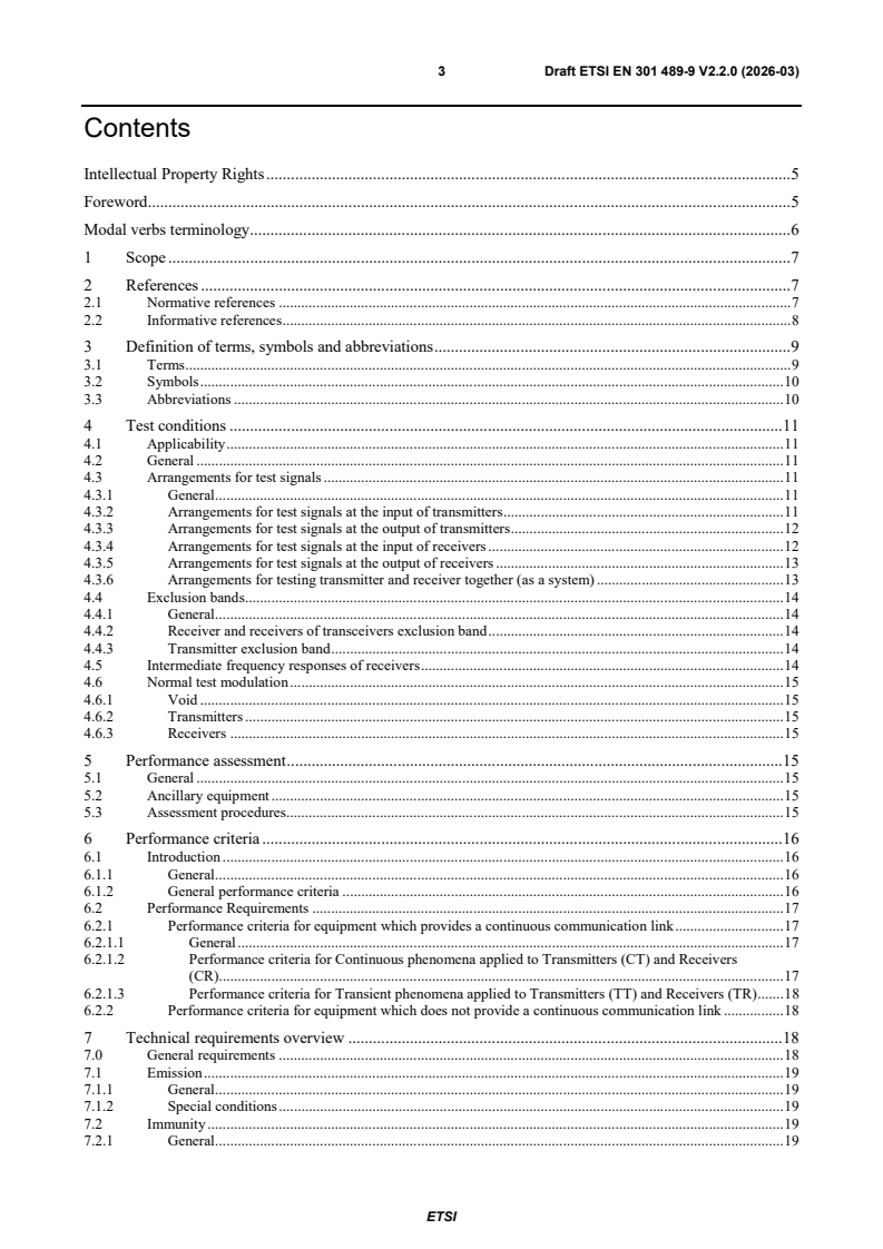
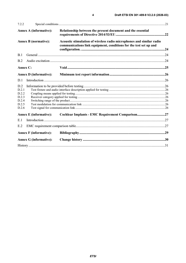
ETSI EN 301 489-9 V2.2.0 (2026-03) - ElectroMagnetic Compatibility (EMC) standard for radio equipment and services; Part 9: Specific conditions for wireless microphones, similar Radio Frequency (RF) audio link equipment, cordless audio, in-ear monitoring and assistive listening devices; Harmonised Standards for ElectroMagnetic Compatibility
ETSI EN 301 489-9 V2.2.1 (2026-07) - ElectroMagnetic Compatibility (EMC) standard for radio equipment and services; Part 9: Specific conditions for wireless microphones, similar Radio Frequency (RF) audio link equipment, cordless audio, in-ear monitoring and assistive listening devices; Harmonised Standards for ElectroMagnetic Compatibility
ETSI EN 301 489-9 V2.2.1 (2026-09) - ElectroMagnetic Compatibility (EMC) standard for radio equipment and services; Part 9: Specific conditions for wireless microphones, similar Radio Frequency (RF) audio link equipment, cordless audio, in-ear monitoring and assistive listening devices; Harmonised Standard for ElectroMagnetic Compatibility

SIST EN 301 489-9 V2.2.1:2026 is the Slovenian adoption of ETSI EN 301 489-9 V2.2.1, a harmonised EMC standard for radio equipment and services. It specifies the test conditions, measurement methods, performance assessment and performance criteria for wireless microphones, similar RF audio link equipment, cordless audio, in-ear monitoring, cochlear implant and assistive listening devices, together with associated ancillary equipment. In practice, it is the EMC reference for manufacturers, test labs and compliance teams working on these audio radio products.
What does SIST EN 301 489-9 V2.2.1:2026 specify?
SIST EN 301 489-9 V2.2.1:2026 covers electromagnetic compatibility for the listed audio radio technologies and their ancillary equipment. It tells the reader how to test them, how to judge performance during and after EMC stress, and how the document relates to the radio spectrum standards used for the antenna port and enclosure-port emissions.
The scope is limited to EMC for the equipment families named in Table 1. The product standards named there handle the radio-spectrum side of the equipment, while this part focuses on EMC behavior of the radio equipment itself.
The document is organized into 7 clauses:
- Clause 1 Scope
- Clause 2 References
- Clause 3 Definition of terms, symbols and abbreviations
- Clause 4 Test conditions
- Clause 5 Performance assessment
- Clause 6 Performance criteria
- Clause 7 Technical requirements overview
| Annex | What it covers |
|---|---|
| Annex A | Relationship with the essential requirements of Directive 2014/53/EU |
| Annex B | Acoustic stimulation and test set-up for wireless radio microphones and similar radio communications link equipment |
| Annex D | Minimum test report information |
| Annex E | EMC requirement comparison for Cochlear Implants |
| Annex F | Bibliography |
| Annex G | Change history |
What are the key requirements of SIST EN 301 489-9 V2.2.1:2026?
SIST EN 301 489-9 V2.2.1:2026 builds on ETSI EN 301 489-1 and then adds product-specific test conditions and acceptance rules for this family of audio radio equipment. The practical result is that a laboratory must set up the right audio and RF stimulation, test the right operating modes, and judge performance against the right category criteria.
Test conditions and signal arrangements
Clause 4 applies the general test conditions from ETSI EN 301 489-1, with specific changes for these products. Handheld and body-worn transmitters are mounted on a non-conductive stand, detachable antennas are fitted as intended, and digitally modulated systems use defined conversion interfaces between analogue and digital domains.
Clause 4 also defines how to inject test signals. For transmitters with an integral or dedicated microphone, Annex B and clause 4.3.2 require acoustic coupling; for other transmitters, the test signal is fed electrically to the most sensitive input. For receivers, the wanted RF input signal is set so the audio path is exercised at full modulation, and the recovered audio is checked with SINAD measurement.
Exclusion bands and receiver responses
Clause 4.4 defines exclusion bands from the switching range of the product. The category of the equipment matters, so the test team must know whether the EUT is in Category 1, 2 or 3 before testing.
Clause 4.5 explains how to identify intermediate frequency responses during immunity tests. If a failure disappears when the test frequency is shifted in the stated way, the response is treated as an intermediate frequency response and disregarded for immunity assessment. In practice, this prevents spurious receiver responses from being mistaken for real EMC failures.
Performance assessment and category-based criteria
Clause 5 requires the test report to capture the intended use and other test details that affect reproducibility. It also gives rules for ancillary equipment, including separate testing when it may be more than 2 m from the radio equipment.
Clause 5 and Clause 6 together make the communication link central to the assessment. The link must be established in the same way the equipment is intended to operate, and the assessment must confirm that functions are maintained, recovered correctly and not altered in an unintended way. Multiple bands, multiple radio technologies and the most sensitive capsule, where relevant, each need assessment.
Clause 6 divides the equipment into three categories:
- Category 1 for professional applications
- Category 2 for consumer equipment used for domestic entertainment
- Category 3 for general consumer purposes
The document then uses performance criteria A, B and C for different disturbance types. Continuous and transient phenomena have different pass/fail logic, and transmitter-only products are also checked to make sure they do not transmit unintentionally in stand-by mode.
Emission and immunity overview
Clause 7 sets out the emission and immunity requirements and points back to ETSI EN 301 489-1 for the detailed methods. Special conditions require the radio equipment to be tested on a channel near the middle of the switching range, and transmitters are operated at maximum rated RF output power during immunity tests. All available operating modes are exercised.
For cochlear implants, Annex E explains how the EMC requirements in this document compare with those in the medical-device framework.
What terms does SIST EN 301 489-9 V2.2.1:2026 define?
- Assistive Listening Device (ALD) - a device for a hearing-impaired person, also described as a hearing aid in this document.
- Assistive Listening System (ALS) - a system that uses electromagnetic, radio or light waves to deliver speech or sound directly to the hearing-impaired person.
- Audio-Frequency Induction-Loop System (AFILS) - a loop-based audio system that creates magnetic fields from audio-frequency current.
- Cochlear Implant (CI) - a surgically implanted device intended to provide a modified sense of sound for severe hearing loss.
- In Ear Monitor (IEM) - a body-worn miniature receiver with earpieces for personal monitoring.
- switching range - the maximum frequency range over which the transmitter or receiver can be used without reprogramming or realignment.
- Wireless Multichannel Audio Systems (WMAS) - wireless audio transmission systems using digital broadband techniques for microphone and in-ear monitor applications.
Who uses SIST EN 301 489-9 V2.2.1:2026?
Manufacturers use SIST EN 301 489-9 V2.2.1:2026 when designing wireless microphones, in-ear monitors, cordless audio devices, assistive listening devices and cochlear implant-related equipment. EMC laboratories use it to set up the test rig, choose the modulation, define the exclusion bands and report the results.
Quality managers, compliance teams and notified-body support teams use it to check whether a product family has been tested against the right EMC criteria for its category and intended use. Buyers and specifiers use it when they need a clear EMC requirement for professional audio, hearing-assistance or similar radio products.
What changed in SIST EN 301 489-9 V2.2.1:2026 from the previous edition?
The change history shows that V2.2.1 updates the earlier 2026 draft work and follows the V2.2.0 step. The listed changes include revised tables for cochlear implants, a revised Annex A clause reference and 3 m condition, updated normative and informative references, removal of the special ESD requirements for cochlear implants, and the addition of the Annex E comparison material.
Which standards are used with SIST EN 301 489-9 V2.2.1:2026?
| Standard | What it contributes |
|---|---|
| ETSI EN 301 489-1 | Common EMC technical requirements and the baseline test framework used throughout this part |
| ETSI EN 300 422-1 | Radio-spectrum technical characteristics for wireless microphones and related audio PMSE up to 3 GHz |
| ETSI EN 300 422-4 | Radio-spectrum standard for assistive listening devices, personal sound amplifiers and inductive systems up to 3 GHz |
| ETSI EN 301 357-1 | Technical characteristics and test methods for cordless audio devices in the 25 MHz to 2 000 MHz range |
| ETSI EN 300 454-1 | Technical characteristics and test methods for wide band audio links |
The scope note also points to EN 61000-3-2 and EN 61000-3-3 for conducted-emission topics below 9 kHz on AC mains ports.
What does the SIST EN 301 489-9 V2.2.1:2026 document contain?
Clause 4 contains the detailed test arrangements for transmitter inputs, receiver inputs and outputs, exclusion bands, intermediate-frequency response checks and normal test modulation. Figures 1 to 4 show the main set-ups, including the acoustic coupling jig for integral or dedicated microphones.
Annex B gives the acoustic stimulation methods used during EMC testing of radio microphones and similar equipment. Annex D lists the minimum information that should be captured in the test report, including the fixture, coupling means, receiver category, switching range and RF test signal.
Annex E compares the cochlear implant EMC requirements in this standard with the medical-device standards used under the Medical Device Regulation.
Buy Documents
ETSI EN 301 489-9 V2.2.0 (2026-03) - ElectroMagnetic Compatibility (EMC) standard for radio equipment and services; Part 9: Specific conditions for wireless microphones, similar Radio Frequency (RF) audio link equipment, cordless audio, in-ear monitoring and assistive listening devices; Harmonised Standards for ElectroMagnetic Compatibility
ETSI EN 301 489-9 V2.2.1 (2026-07) - ElectroMagnetic Compatibility (EMC) standard for radio equipment and services; Part 9: Specific conditions for wireless microphones, similar Radio Frequency (RF) audio link equipment, cordless audio, in-ear monitoring and assistive listening devices; Harmonised Standards for ElectroMagnetic Compatibility
ETSI EN 301 489-9 V2.2.1 (2026-09) - ElectroMagnetic Compatibility (EMC) standard for radio equipment and services; Part 9: Specific conditions for wireless microphones, similar Radio Frequency (RF) audio link equipment, cordless audio, in-ear monitoring and assistive listening devices; Harmonised Standard for ElectroMagnetic Compatibility
Get Certified
Connect with accredited certification bodies for this standard

ANCE
Mexican certification and testing association.

Intertek Slovenia
Intertek testing, inspection, and certification services in Slovenia.

LNE (Laboratoire National de Métrologie et d'Essais)
French national laboratory for metrology and testing.
Sponsored listings
Frequently Asked Questions
SIST EN 301 489-9 V2.2.1:2026 is a standard published by the Slovenian Institute for Standardization (SIST). Its full title is "ElectroMagnetic Compatibility (EMC) standard for radio equipment and services - Part 9: Specific conditions for wireless microphones, similar Radio Frequency (RF) audio link equipment, cordless audio, in-ear monitoring and assistive listening devices - Harmonised Standards for ElectroMagnetic Compatibility". This standard covers: The present document specifies technical characteristics and methods of measurements for wireless microphones, similar RF audio link equipment, cordless audio (including low power Band II transmitters), in-ear monitoring, cochlear implant and assistive listening devices, intended for the transmission of music and speech including the associated ancillary equipment in respect of electromagnetic compatibility, as detailed in table 1. Technical specifications related to the antenna port and emissions from the enclosure port of the radio equipment are out of scope of the present document. Such technical specifications are found in the relevant product standards for the effective use of the radio spectrum, see table 1. The present document specifies the applicable test conditions, performance assessment and performance criteria for wireless microphones, similar RF audio link equipment, cordless audio, in-ear monitoring, ALD and Cochlear Implants and associated ancillary equipment. This equipment can use analogue or digital modulation techniques. For cochlear implants more stringent EMC standards exist and Annex E provides information on its relationship to the present document. NOTE 1: Technical specifications related to conducted emission EMC requirements below 9 kHz on the AC mains port of radio equipment are out of scope of the present document. Such technical specifications are normally found in the relevant product family standards for AC mains powered equipment (e.g. EN 61000-3-2 [i.6] and EN 61000-3-3 [i.7]). NOTE 2: The relationship between the present document and essential requirements of article 3.1(b) of Directive 2014/53/EU [i.1] is given in Annex A.
The present document specifies technical characteristics and methods of measurements for wireless microphones, similar RF audio link equipment, cordless audio (including low power Band II transmitters), in-ear monitoring, cochlear implant and assistive listening devices, intended for the transmission of music and speech including the associated ancillary equipment in respect of electromagnetic compatibility, as detailed in table 1. Technical specifications related to the antenna port and emissions from the enclosure port of the radio equipment are out of scope of the present document. Such technical specifications are found in the relevant product standards for the effective use of the radio spectrum, see table 1. The present document specifies the applicable test conditions, performance assessment and performance criteria for wireless microphones, similar RF audio link equipment, cordless audio, in-ear monitoring, ALD and Cochlear Implants and associated ancillary equipment. This equipment can use analogue or digital modulation techniques. For cochlear implants more stringent EMC standards exist and Annex E provides information on its relationship to the present document. NOTE 1: Technical specifications related to conducted emission EMC requirements below 9 kHz on the AC mains port of radio equipment are out of scope of the present document. Such technical specifications are normally found in the relevant product family standards for AC mains powered equipment (e.g. EN 61000-3-2 [i.6] and EN 61000-3-3 [i.7]). NOTE 2: The relationship between the present document and essential requirements of article 3.1(b) of Directive 2014/53/EU [i.1] is given in Annex A.
SIST EN 301 489-9 V2.2.1:2026 is classified under the following ICS (International Classification for Standards) categories: 33.060.01 - Radiocommunications in general; 33.100.01 - Electromagnetic compatibility in general; 33.160.50 - Accessories. The ICS classification helps identify the subject area and facilitates finding related standards.
SIST EN 301 489-9 V2.2.1:2026 is available in PDF format for immediate download after purchase. The document can be added to your cart and obtained through the secure checkout process. Digital delivery ensures instant access to the complete standard document.
Standards Content (Sample)
Draft ETSI EN 301 489-9 V2.2.0 (2026-03)
HARMONISED EUROPEAN STANDARD
ElectroMagnetic Compatibility (EMC) standard for radio
equipment and services;
Part 9: Specific conditions for wireless microphones, similar
Radio Frequency (RF) audio link equipment, cordless audio,
in-ear monitoring and assistive listening devices;
Harmonised Standards for ElectroMagnetic Compatibility
2 Draft ETSI EN 301 489-9 V2.2.0 (2026-03)
Reference
REN/ERM-EMC-425
Keywords
audio, digital, EMC, harmonised standard, radio,
radio mic, regulation
ETSI
650 Route des Lucioles
F-06921 Sophia Antipolis Cedex - FRANCE
Tel.: +33 4 92 94 42 00 Fax: +33 4 93 65 47 16
Siret N° 348 623 562 00017 - APE 7112B
Association à but non lucratif enregistrée à la
Sous-Préfecture de Grasse (06) N° w061004871
Important notice
The present document can be downloaded from the
ETSI Search & Browse Standards application.
The present document may be made available in electronic versions and/or in print. The content of any electronic and/or
print versions of the present document shall not be modified without the prior written authorization of ETSI. In case of any
existing or perceived difference in contents between such versions and/or in print, the prevailing version of an ETSI
deliverable is the one made publicly available in PDF format on ETSI deliver repository.
Users should be aware that the present document may be revised or have its status changed,
this information is available in the Milestones listing.
If you find errors in the present document, please send your comments to
the relevant service listed under Committee Support Staff.
If you find a security vulnerability in the present document, please report it through our
Coordinated Vulnerability Disclosure (CVD) program.
Notice of disclaimer & limitation of liability
The information provided in the present deliverable is directed solely to professionals who have the appropriate degree of
experience to understand and interpret its content in accordance with generally accepted engineering or
other professional standard and applicable regulations.
No recommendation as to products and services or vendors is made or should be implied.
In no event shall ETSI be held liable for loss of profits or any other incidental or consequential damages.
Any software contained in this deliverable is provided "AS IS" with no warranties, express or implied, including but not
limited to, the warranties of merchantability, fitness for a particular purpose and non-infringement of intellectual property
rights and ETSI shall not be held liable in any event for any damages whatsoever (including, without limitation, damages
for loss of profits, business interruption, loss of information, or any other pecuniary loss) arising out of or related to the use
of or inability to use the software.
Copyright Notification
No part may be reproduced or utilized in any form or by any means, electronic or mechanical, including photocopying and
microfilm except as authorized by written permission of ETSI.
The content of the PDF version shall not be modified without the written authorization of ETSI.
The copyright and the foregoing restriction extend to reproduction in all media.
© ETSI 2026.
All rights reserved.
ETSI
3 Draft ETSI EN 301 489-9 V2.2.0 (2026-03)
Contents
Intellectual Property Rights . 5
Foreword . 5
Modal verbs terminology . 6
1 Scope . 7
2 References . 7
2.1 Normative references . 7
2.2 Informative references . 8
3 Definition of terms, symbols and abbreviations . 9
3.1 Terms . 9
3.2 Symbols . 10
3.3 Abbreviations . 10
4 Test conditions . 11
4.1 Applicability . 11
4.2 General . 11
4.3 Arrangements for test signals . 11
4.3.1 General . 11
4.3.2 Arrangements for test signals at the input of transmitters . 11
4.3.3 Arrangements for test signals at the output of transmitters . 12
4.3.4 Arrangements for test signals at the input of receivers . 12
4.3.5 Arrangements for test signals at the output of receivers . 13
4.3.6 Arrangements for testing transmitter and receiver together (as a system) . 13
4.4 Exclusion bands . 14
4.4.1 General . 14
4.4.2 Receiver and receivers of transceivers exclusion band . 14
4.4.3 Transmitter exclusion band . 14
4.5 Intermediate frequency responses of receivers . 14
4.6 Normal test modulation . 15
4.6.1 Void . 15
4.6.2 Transmitters . 15
4.6.3 Receivers . 15
5 Performance assessment . 15
5.1 General . 15
5.2 Ancillary equipment . 15
5.3 Assessment procedures . 15
6 Performance criteria . 16
6.1 Introduction . 16
6.1.1 General . 16
6.1.2 General performance criteria . 16
6.2 Performance Requirements . 17
6.2.1 Performance criteria for equipment which provides a continuous communication link . 17
6.2.1.1 General . 17
6.2.1.2 Performance criteria for Continuous phenomena applied to Transmitters (CT) and Receivers
(CR). 17
6.2.1.3 Performance criteria for Transient phenomena applied to Transmitters (TT) and Receivers (TR) . 18
6.2.2 Performance criteria for equipment which does not provide a continuous communication link . 18
7 Technical requirements overview . 18
7.0 General requirements . 18
7.1 Emission . 19
7.1.1 General . 19
7.1.2 Special conditions . 19
7.2 Immunity . 19
7.2.1 General . 19
ETSI
4 Draft ETSI EN 301 489-9 V2.2.0 (2026-03)
7.2.2 Special conditions . 21
Annex A (informative): Relationship between the present document and the essential
requirements of Directive 2014/53/EU . 22
Annex B (normative): Acoustic stimulation of wireless radio microphones and similar radio
communications link equipment, conditions for the test set up and
configuration. . 24
B.1 General . 24
B.2 Audio excitation . 24
Annex C: Void . 25
Annex D (informative): Minimum test report information . 26
D.1 Introduction . 26
D.2 Information to be provided before testing . 26
D.2.1 Test fixture and audio interface description applied for testing . 26
D.2.2 Coupling means applied for testing . 26
D.2.3 Receiver category applied for testing . 26
D.2.4 Switching range of the product . 26
D.2.5 Test modulation for communication link . 26
D.2.6 Test signal for communication link . 26
Annex E (informative): Cochlear Implants - EMC Requirement Comparison. 27
E.1 Introduction . 27
E.2 EMC requirement comparison table . 27
Annex F (informative): Bibliography . 29
Annex G (informative): Change history . 30
History . 31
ETSI
5 Draft ETSI EN 301 489-9 V2.2.0 (2026-03)
Intellectual Property Rights
Essential patents
IPRs essential or potentially essential to normative deliverables may have been declared to ETSI. The declarations
pertaining to these essential IPRs, if any, are publicly available for ETSI members and non-members, and can be
found in ETSI SR 000 314: "Intellectual Property Rights (IPRs); Essential, or potentially Essential, IPRs notified to
ETSI in respect of ETSI standards", which is available from the ETSI Secretariat. Latest updates are available on the
ETSI IPR online database.
Pursuant to the ETSI Directives including the ETSI IPR Policy, no investigation regarding the essentiality of IPRs,
including IPR searches, has been carried out by ETSI. No guarantee can be given as to the existence of other IPRs not
referenced in ETSI SR 000 314 (or the updates on the ETSI Web server) which are, or may be, or may become,
essential to the present document.
Trademarks
The present document may include trademarks and/or tradenames which are asserted and/or registered by their owners.
ETSI claims no ownership of these except for any which are indicated as being the property of ETSI, and conveys no
right to use or reproduce any trademark and/or tradename. Mention of those trademarks in the present document does
not constitute an endorsement by ETSI of products, services or organizations associated with those trademarks.
DECT™, PLUGTESTS™, UMTS™ and the ETSI logo are trademarks of ETSI registered for the benefit of its
Members. 3GPP™, LTE™ and 5G™ logo are trademarks of ETSI registered for the benefit of its Members and of the
3GPP Organizational Partners. oneM2M™ logo is a trademark of ETSI registered for the benefit of its Members and of ®
the oneM2M Partners. GSM and the GSM logo are trademarks registered and owned by the GSM Association.
Foreword
This draft Harmonised European Standard (EN) has been produced by ETSI Technical Committee Electromagnetic
compatibility and Radio spectrum Matters (ERM), and is now submitted for the combined Public Enquiry and Vote
phase of the ETSI Standardisation Request deliverable Approval Procedure (SRdAP).
The present document has been prepared under the Commission's standardisation request C(2015) 5376 final [i.3] to
provide one voluntary means of conforming to the essential requirements of Directive 2014/53/EU on the harmonisation
of the laws of the Member States relating to the making available on the market of radio equipment and repealing
Directive 1999/5/EC [i.1].
Once the present document is cited in the Official Journal of the European Union under that Directive, compliance with
the normative clauses of the present document given in table A.1 confers, within the limits of the scope of the present
document, a presumption of conformity with the corresponding essential requirements of that Directive and associated
EFTA regulations.
The present document is part 9 of a multi-part deliverable. Full details of the entire series can be found in part 1 [1].
Proposed national transposition dates
Date of latest announcement of this EN (doa): 3 months after ETSI publication
Date of latest publication of new National Standard
or endorsement of this EN (dop/e): 6 months after doa
Date of withdrawal of any conflicting National Standard (dow): 18 months after doa
ETSI
6 Draft ETSI EN 301 489-9 V2.2.0 (2026-03)
Modal verbs terminology
In the present document "shall", "shall not", "should", "should not", "may", "need not", "will", "will not", "can" and
"cannot" are to be interpreted as described in clause 3.2 of the ETSI Drafting Rules (Verbal forms for the expression of
provisions).
"must" and "must not" are NOT allowed in ETSI deliverables except when used in direct citation.
ETSI
7 Draft ETSI EN 301 489-9 V2.2.0 (2026-03)
1 Scope
The present document specifies technical characteristics and methods of measurements for wireless microphones,
similar RF audio link equipment, cordless audio (including low power Band II transmitters), in-ear monitoring, cochlear
implant and assistive listening devices, intended for the transmission of music and speech including the associated
ancillary equipment in respect of electromagnetic compatibility, as detailed in table 1.
Technical specifications related to the antenna port and emissions from the enclosure port of the radio equipment are
out of scope of the present document. Such technical specifications are found in the relevant product standards for the
effective use of the radio spectrum, see table 1.
The present document specifies the applicable test conditions, performance assessment and performance criteria for
wireless microphones, similar RF audio link equipment, cordless audio, in-ear monitoring, ALD and Cochlear Implants
and associated ancillary equipment. This equipment can use analogue or digital modulation techniques.
Low quality speech applications as toy microphones, baby phones etc. operating at frequencies below 50 MHz,
occupied bandwidth < 25 kHz and operating according to CEPT/ERC/REC 70-03 [i.2], Annex 1 are out of scope of the
present document.
Table 1: Radio Technologies in scope of the present document
Technology ETSI Standard
Wireless Microphones
In-Ear Monitoring ETSI EN 300 422-1 [2]
Wireless Multichannel Audio Systems
Assistive Listening Devices
Cochlear Implants
Neck loops-T-Coil ETSI EN 300 422-4 [i.13]
Personal Sound Amplifiers
Hearing Aid Systems
Cordless Audio
Low Power FM Tx
ETSI EN 301 357-1 [i.12]
low Power Radio Microphones
In-Ear Monitoring
Audio Links ETSI EN 300 454-1 [i.11]
For cochlear implants more stringent EMC standards exist and Annex E provides information on its relationship to the
present document.
NOTE 1: Technical specifications related to conducted emission EMC requirements below 9 kHz on the AC mains
port of radio equipment are out of scope of the present document. Such technical specifications are
normally found in the relevant product family standards for AC mains powered equipment (e.g.
EN 61000-3-2 [i.6] and EN 61000-3-3 [i.7]).
NOTE 2: The relationship between the present document and essential requirements of article 3.1(b) of
Directive 2014/53/EU [i.1] is given in Annex A.
2 References
2.1 Normative references
References are either specific (identified by date of publication and/or edition number or version number) or
non-specific. For specific references, only the cited version applies. For non-specific references, the latest version of the
referenced document (including any amendments) applies.
Referenced documents which are not found to be publicly available in the expected location might be found in the
ETSI docbox.
NOTE: While any hyperlinks included in this clause were valid at the time of publication, ETSI cannot guarantee
their long-term validity.
ETSI
8 Draft ETSI EN 301 489-9 V2.2.0 (2026-03)
The following referenced documents are necessary for the application of the present document.
[1] ETSI EN 301 489-1 (V2.2.3) (11-2019): "ElectroMagnetic Compatibility (EMC) standard for
radio equipment and services; Part 1: Common technical requirements; Harmonised Standard for
ElectroMagnetic Compatibility".
[2] ETSI EN 300 422-1 (V2.2.1) (11-2021): "Wireless Microphones; Audio PMSE up to 3 GHz;
Part 1: Audio PMSE Equipment up to 3 GHz; Harmonised Standard for access to radio spectrum".
2.2 Informative references
References are either specific (identified by date of publication and/or edition number or version number) or
non-specific. For specific references, only the cited version applies. For non-specific references, the latest version of the
referenced document (including any amendments) applies.
NOTE: While any hyperlinks included in this clause were valid at the time of publication, ETSI cannot guarantee
their long-term validity.
The following referenced documents may be useful in implementing an ETSI deliverable or add to the reader's
understanding, but are not required for conformance to the present document.
[i.1] Directive 2014/53/EU of the European Parliament and of the Council of 16 April 2014 on the
harmonisation of the laws of the Member States relating to the making available on the market of
radio equipment and repealing Directive 1999/5/EC.
[i.2] CEPT/ERC/REC 70-03: "Relating to the use of Short Range Devices (SRD)".
[i.3] Commission Implementing Decision C(2015) 5376 final of 4.8.2015 on a standardisation request
to the European Committee for Electrotechnical Standardisation and to the European
Telecommunications Standards Institute as regards radio equipment in support of Directive
2014/53/EU of the European Parliament and of the Council.
[i.4] Void.
[i.5] Void.
[i.6] IEC EN 61000-3-2 (2014): "Electromagnetic compatibility (EMC) - Part 3-2: Limits -Limits for
harmonic current emissions (equipment input current ≤ 16 A per phase)".
[i.7] IEC EN 61000-3-3 (2013): "Electromagnetic compatibility (EMC) - Part 3-3: Limits -Limitation
of voltage changes, voltage fluctuations and flicker in public low-voltage supply systems, for
equipment with rated current ≤ 16 A per phase and not subject to conditional connection".
[i.8] EN 45502-2-3 (2010): "Active implantable medical devices - Part 2-3: Particular requirements for
cochlear and auditory brainstem implant systems" (Produced by CENELEC).
[i.9] EN 60601-1-2 (2015) + A1(2021): "Medical electrical equipment-General requirements for basic
safety and essential performance. Collateral Standard: Electromagnetic disturbances.
Requirements and tests" (Produced by CENELEC).
[i.10] Regulation (EU) 2017/745 of the European Parliament and of the Council of 5 April 2017 on
medical devices, amending Directive 2001/83/EC, Regulation (EC) No 178/2002 and
Regulation (EC) No 1223/2009 and repealing Council Directives 90/385/EEC and 93/42/EEC.
[i.11] ETSI EN 300 454-1 (V1.1.2) (08-2000): "Electromagnetic compatibility and Radio spectrum
Matters (ERM); Wide band audio links; Part 1: Technical characteristics and test methods".
[i.12] ETSI EN 301 357-1 (V1.4.1) (11-2008): "Electromagnetic compatibility and Radio spectrum
Matters (ERM); Cordless audio devices in the range 25 MHz to 2 000 MHz; Part 1: Technical
characteristics and test methods".
ETSI
9 Draft ETSI EN 301 489-9 V2.2.0 (2026-03)
[i.13] ETSI EN 300 422-4 (V2.1.1) (05-2017): "Wireless Microphones; Audio PMSE up to 3 GHz;
Part 4: Assistive Listening Devices including personal sound amplifiers and inductive systems up
to 3 GHz; Harmonised Standard covering the essential requirements of article 3.2 of
Directive 2014/53/EU".
3 Definition of terms, symbols and abbreviations
3.1 Terms
For the purposes of the present document, the terms given in ETSI EN 301 489-1 [1] and the following apply:
Assistive Listening Device (ALD) for hearing impaired: aid for a hearing-impaired person, also known as a hearing
aid
Assistive Listening System (ALS) for hearing impaired: systems utilizing electromagnetic, radio or light waves, or a
combination of these, to transmit the acoustic signal from the source (e.g. a loudspeaker or a person talking) directly to
the hearing-impaired person
NOTE: Both aids for the hearing impaired and Assistive Listening devices would normally be prescribed by a
hearing professional.
Audio-Frequency Induction-Loop System (AFILS): system including induction loop amplifier(s), microphones
and/or other signal sources, in which magnetic fields are created by the flow of audio-frequency current in a conductor
arranged in the form of a loop or coil
Cochlear Implant (CI): surgically implanted neuroprosthetic device intended to provide a person with moderate to
profound sensorineural hearing loss a modified sense of sound
NOTE: CI bypasses the normal acoustic hearing process to replace it with electric signals which directly stimulate
the auditory nerve.
Cochlear Implants (CI) transformer coils: two transformer windings separated by the human skin
NOTE: For the purpose of the present document the CI transformer coils of a conventional CI are using magnetic
induction for providing power and data to the implant from the external sound processor/hearing aid and
not to recharge the CI by WPT.
companding: method of audio processing that compresses the audio dynamic range before transmission and then
provides matching expansion of the signal in the receiver
NOTE: The method is used to improve the audio performance in the RF link.
hearing aid system: broadcast radio communication system comprising one transmitter (up to 500 mW in the band
169,4 MHz to 169,8125 MHz), which is installed at a fixed location in a large auditorium.
EXAMPLE: In a church or theatre and one or more receivers, where each receiver can have wired or inductive
connection to a hearing aid
In Ear Monitor (IEM): body worn miniature receiver with earpieces for personal monitoring of single- or
dual-channel sound
integral antenna: antenna designed to be connected to the equipment without the use of a 50 Ω external connector and
considered to be part of the equipment
NOTE: An integral antenna may be fitted internally or externally to the equipment.
low power band 2 transmitters: band II LPD (low power devices) up to 200 kHz bandwidth and analogue modulation
mobile equipment: receiver, transmitter or transmitter/receiver (transceiver) intended for installation and use in a
vehicle, and powered by the main battery of the vehicle
neck loop: insulated wire loop antenna which goes around the neck connecting to a small unit and communicates with
the T-coil receiver contained within a hearing aid, ALD or Cochlear implant
ETSI
10 Draft ETSI EN 301 489-9 V2.2.0 (2026-03)
personal hearing aid system: radio communication system comprising of a transmitter, which can be handheld, on a
table or around the neck of a hearing-impaired person and one or more receivers, where each receiver can have wired or
inductive connection to a hearing aid
personal sound amplifier: body-worn device providing sound amplification
radio microphone: microphone combined with a radio transmitter as a handheld or bodypack device; sometimes
referred to as wireless microphone
switching range: maximum frequency range over which the receiver or transmitter can be operated without
reprogramming or realignment
T-Coil: small wire coiled around a rod located inside the hearing aids, works as an antenna to pick up magnetic signals
and streams them as sound into the hearing aids
vehicle power supply: battery used for the primary operation of the vehicle, i.e. the ignition or starting of the vehicle
Wireless Multichannel Audio Systems (WMAS): wireless audio transmission systems using digital broadband
transmission techniques for microphone and in-ear monitor system applications, and other multichannel audio PMSE
use, e.g. with the ability to support three or more audio channels per MHz
3.2 Symbols
Void.
3.3 Abbreviations
For the purposes of the present document, the abbreviations given in ETSI EN 301 489-1 [1] and the following apply:
AFILS Audio-Frequency Induction-Loop System
ALD Assistive Listening Device
ALS Assistive Listening System
CI Cochlear Implant
CR Continuous phenomena applied to Receivers
CT Continuous phenomena applied to Transmitters
e.r.p. effective radiated power
EMC ElectroMagnetic Compatibility
EUT Equipment Under Test
IEM In-Ear Monitoring
LPD Low Power Device
PMR Professional Mobile Radio
RF Radio Frequency
SINAD Ratio of (Signal + Noise + Distortion) to (Noise + Distortion)
TR Transient phenomena applied to Receivers
TT Transient phenomena applied to Transmitters
WMAS Wireless Multichannel Audio Systems
WPT Wireless Power Transmission
ETSI
11 Draft ETSI EN 301 489-9 V2.2.0 (2026-03)
4 Test conditions
4.1 Applicability
For the purposes of the present document, the test conditions of ETSI EN 301 489-1 [1], clause 4 shall apply except
where modified in clauses 4.2 to 4.6.
4.2 General
For emission and immunity tests the test modulation, test arrangements, etc., as specified in the present document,
clauses 4.2 to 4.6 shall apply.
For the purpose of EMC tests, body-worn or handheld transmitters shall be mounted on a non-conductive stand at least
0,8 m from any conducting surface. The EUT and any other equipment required for the performance assessment before,
during, and after the conclusion of the tests, shall be connected according to the intended use.
Whenever the EUT is provided with a detachable antenna, it shall be tested with the antenna fitted according to the
intended use.
For immunity tests, if the equipment is of a category which permits it, a communications link shall be established at the
start of the test and maintained during the test.
The test conditions shall be as follows:
• the transmitter shall be operated at its normal maximum RF output power modulated with a suitable
modulation signal (see clause 4.6.2);
• for standalone receivers or receivers of transceivers operating in simplex mode, the wanted RF input signal,
coupled to the receiver, shall be modulated with a suitable modulation signal (see clause 4.6.3);
• for duplex transceivers, the wanted RF input signal, coupled to the receiver, shall be modulated with a suitable
modulation signal (see clause 4.6.3). The transmitter shall be operated at its normal maximum output power,
modulated with the test modulation signal, coupled to the transmitter from the output of the receiver (repeater
mode);
• digitally modulated systems shall use a defined interface to convert between analogue and digital domain (and
vice versa).
4.3 Arrangements for test signals
4.3.1 General
The provisions of ETSI EN 301 489-1 [1], clause 4.2 shall apply.
4.3.2 Arrangements for test signals at the input of transmitters
The provisions of Annex B and of ETSI EN 301 489-1 [1], clause 4.2.1 shall apply with the following modifications.
For transmitters designed to operate from an integral or dedicated microphone (see figure 2), an acoustic coupling
device shall be used to inject the normal test modulation signal (see figure 3).
The transmitter shall be tested at its most sensitive input.
For equipment not designed to use an integral or dedicated microphone, the test signal shall be fed in electrical form to
the most sensitive input socket (see figure 1) using maximum length cables as normally supplied with the equipment.
The modulation signal used for the tests shall be a 1 kHz sine wave tone at a level expected to obtain 100 % audio
modulation.
ETSI
12 Draft ETSI EN 301 489-9 V2.2.0 (2026-03)
In the case of systems with a digital audio input and outputs this test signal shall be presented via a suitable test fixture
converting the analogue signal to the digital domain and vice-versa.
4.3.3 Arrangements for test signals at the output of transmitters
The provisions of ETSI EN 301 489-1 [1], clause 4.2.2 shall apply.
4.3.4 Arrangements for test signals at the input of receivers
The provisions of ETSI EN 301 489-1 [1], clause 4.2.3 shall apply with the following modifications.
The wanted RF input signal to the receiver should be modulated with a suitable signal corresponding to 100 % audio
modulation (maximum channel loading). If it is not appropriate to provide a modulated RF signal to the receiver, the
test may be performed using an unmodulated wanted RF input signal.
For analogue radio microphones the level of the wanted RF input signal shall be set to a value 60 dB above the
threshold sensitivity of the receiver. Where a transmitter is used to setup a communication link, an attenuator in the
EUT input may be necessary.
For digital microphone receivers, tested either with an RF generator or in a system setup with a microphone transmitter,
the maximum rated RF output power of the transmitter shall be used to establish a stable communication link during
emission and immunity testing, but this level shall not exceed 50 mW e.r.p., which is the maximum allowed RF output
power defined in ETSI EN 300 422-1 [2], clause 4.2.1.2.
Figure 1: Test configuration for integral antenna; transmitter operation - electrical input
Figure 2: Test configuration for integral antenna; transmitter operation - acoustic input
ETSI
13 Draft ETSI EN 301 489-9 V2.2.0 (2026-03)
Funnels (optional) Transducer
E.U.T.
Audio
signal
generator
Acoustic tube
Power
amplifier
Suggested minimum length 1 m
(optional)
Figure 3: Example of acoustic coupling jig
NOTE: The RF generator can be a companion transmitter sited inside the test chamber, if necessary.
Figure 4: Test configuration for integral antenna; receiver operation
4.3.5 Arrangements for test signals at the output of receivers
The provisions of ETSI EN 301 489-1 [1], clause 4.2.4 shall apply with the following modification.
The audio frequency output of the equipment shall be coupled to the SINAD measuring system outside of the test
environment.
The characteristics of the SINAD measuring system should be such that the upper -3 dB frequency of its detector part is
to exceed 16 kHz, and its electrical measurement flatness error between 40 Hz and 16 kHz is not to exceed ±2 dB.
In the case of systems with a digital audio output, a test fixture to convert from digital to analogue signals shall be used.
4.3.6 Arrangements for testing transmitter and receiver together (as a
system)
In case of digitally modulated systems, test fixtures for converting from the analogue to the digital domain and vice
versa shall be used.
ETSI
14 Draft ETSI EN 301 489-9 V2.2.0 (2026-03)
4.4 Exclusion bands
4.4.1 General
The provisions of ETSI EN 301 489-1 [1], clause 4.3 shall apply.
4.4.2 Receiver and receivers of transceivers exclusion band
The exclusion band for receivers and receivers of transceivers is the frequency range determined by the switching
range, extended as follows:
1) Category 1 and 2 equipment (as defined in clause 6):
- the lower frequency of the exclusion band is the lower frequency of the switching range, minus 5 % of
the centre frequency of the switching range;
- the upper frequency of the exclusion band is the upper frequency of the switching range, plus 5 % of the
centre frequency of the switching range.
2) Category 3 equipment (as defined in clause 6):
- the lower frequency of the exclusion band is the lower frequency of the switching range, minus 5 % of
the centre frequency of the switching range, or minus 10 MHz, whichever will result in the lowest
frequency;
- the upper frequency of the exclusion band is the upper frequency of the switching range, plus 5 % of the
centre frequency of the switching range, or plus 10 MHz, whichever will result in the highest frequency.
The category of equipment shall be determined according to clause 6 of the present document before testing.
4.4.3 Transmitter exclusion band
The lower frequency of the exclusion band is the lower frequency of the switching range, minus 5 % of the centre
frequency of the switching range.
The upper frequency of the exclusion band is the upper frequency of the switching range, plus 5 % of the centre
frequency of the switching range.
4.5 Intermediate frequency responses of receivers
Responses on receivers occurring during the immunity tests at discrete frequencies which are intermediate frequency
responses (spurious responses), are identified by the following method.
If during the test the immunity RF test signal causes non-compliance of the receiver with the specified performance
criteria (see clause 6), it is necessary to evaluate whether this non-compliance is due to an intermediate frequency
response or a wideband phenomenon.
Therefore, the frequency of the test signal is increased by an amount equal to twice the nominal 6 dB bandwidth of the
IF filter immediately preceding the demodulator of the receiver, or the bandwidth over which the equipment is intended
to operate. The test is repeated with the frequency of the test signal decreased by the same amount. If the receiver is
then in either or both frequency offset cases in compliance with the specified performance criteria, the response is
considered as an intermediate frequency response. If the receiver still does not comply with the specified performance
criteria, this can be due to the fact that the offset has made the frequency of the unwanted signal correspond to the
frequency of another intermediate frequency response. Under these circumstances the procedure is repeated with an
increase and decrease of the frequency of the test signal adjusted two and a half times the bandwidth referred to above.
If the receiver still does not comply with the specified performance criteria in either or both frequency offset cases, the
phenomena is considered wide band and therefore an EMC problem and the equipment fails the test.
For immunity tests, intermediate frequency responses shall be disregarded.
ETSI
15 Draft ETSI EN 301 489-9 V2.2.0 (2026-03)
4.6 Normal test modulation
4.6.1 Void
4.6.2 Transmitters
The transmitter shall be modulated with a sinusoidal audio frequency signal of 1 000 Hz, provided either by an acoustic
coupling means or by a shielded transmission line (e.g. a coaxial cable). The level of this audio signal shall be adjusted
corresponding to 100 % audio modulation (maximum channel loading) of the wanted RF carrier.
For digitally modulated systems, a test fixture to allow for testing equivalent to 100 % audio modulation level shall be
used.
4.6.3 Receivers
The receiver's wanted RF input signal shall be set to the operation frequency of the receiver within the designated
operation frequency band and modulated with a sinusoidal audio frequency of 1 000 Hz, provided either by a test
antenna located within the test environment (integral antenna receivers) or a shielded transmission line such as a coaxial
cable (non-integral antenna receivers). The level of the modulation signal shall be adjusted resulting in 100 % audio
modulation (maximum channel loading) of the receivers wanted RF input signal.
For digitally modulated systems, a test fixture to allow for testing equivalent to 100 % audio modulation level shall be
used.
5 Performance assessment
5.1 General
At the time of submission of the equipment for test, the parameters of the intended use and other important testing
details not described in the present document should be recorded in the test report (see informative Annex D of the
present document).
5.2 Ancillary equipment
Ancillary equipment shall be tested and assessed by applying the provisions of the present document in either of the
following methods:
• Separately to the ancillary equipment with the radio equipment outside of the measurement area but still
connected to the ancillary equipment. This is used where according to the intended use of the equipment, the
ancillary equipment can be more than 2m from the radio equipment.
• Otherwise, the combination of ancillary equipment and radio equipment shall be both within the measurement
area.
If the first option above is chosen, then no exclusion bands shall be applied to the ancillary equipment.
5.3 Assessment procedures
The performance assessment shall be based upon:
• maintaining the function(s);
• the way the eventual loss of function(s) can be recovered;
• unintentional behaviour of the EUT.
ETSI
16 Draft ETSI EN 301 489-9 V2.2.0 (2026-03)
The test system shall set up a communications link in the same manner as the Equipment Under Test's (EUT) intended
use.
The assessment procedure shall verify that the communications link is maintained and that there is no loss of user
control functions or loss of critical stored data.
Where the EUT is capable of operation in multiple frequency bands, each band shall be subject to assessment.
Where the EUT is capable of operating in multiple radio technologies, the operation of each technology shall be
assessed.
Where the EUT is a transmitter able to operate with different capsules, the most sensitive capsule shall be tested as the
representative capsule and be subject to the assessment.
6 Performance criteria
6.1 Introduction
6.1.1 General
The product family of wireless microphones and similar RF audio link equipment identified in table 1 and associated
ancillary equipment is divided into three categories of equipment, each having its own set of performance criteria:
• Category 1 equipment comprises wireless microphones, similar RF audio link equipment, and associated
ancillary equipment intended for professional applications.
• Category 2 equipment comprises consumer wireless microphones, cordless audio devices, in-ear monitoring
devices and associated ancillary equipment intended for domestic entertainment.
• Category 3 equipment comprises consumer wireless microphones, cordless audio, wireless headphones and
associated ancillary equipment intended for general consumer purposes.
The establishment of the communication link at the start of the test, its maintenanc
...
Final draft ETSI EN 301 489-9 V2.2.1 (2026-07)
HARMONISED EUROPEAN STANDARD
ElectroMagnetic Compatibility (EMC) standard for radio
equipment and services;
Part 9: Specific conditions for wireless microphones, similar
Radio Frequency (RF) audio link equipment, cordless audio,
in-ear monitoring and assistive listening devices;
Harmonised Standards for ElectroMagnetic Compatibility
2 Final draft ETSI EN 301 489-9 V2.2.1 (2026-07)
Reference
REN/ERM-EMC-425
Keywords
audio, digital, EMC, harmonised standard, radio,
radio mic, regulation
ETSI
650 Route des Lucioles
F-06921 Sophia Antipolis Cedex - FRANCE
Tel.: +33 4 92 94 42 00 Fax: +33 4 93 65 47 16
Siret N° 348 623 562 00017 - APE 7112B
Association à but non lucratif enregistrée à la
Sous-Préfecture de Grasse (06) N° w061004871
Important notice
The present document can be downloaded from the
ETSI Search & Browse Standards application.
The present document may be made available in electronic versions and/or in print. The content of any electronic and/or
print versions of the present document shall not be modified without the prior written authorization of ETSI. In case of any
existing or perceived difference in contents between such versions and/or in print, the prevailing version of an ETSI
deliverable is the one made publicly available in PDF format on ETSI deliver repository.
Users should be aware that the present document may be revised or have its status changed,
this information is available in the Milestones listing.
If you find errors in the present document, please send your comments to
the relevant service listed under Committee Support Staff.
If you find a security vulnerability in the present document, please report it through our
Coordinated Vulnerability Disclosure (CVD) program.
Notice of disclaimer & limitation of liability
The information provided in the present deliverable is directed solely to professionals who have the appropriate degree of
experience to understand and interpret its content in accordance with generally accepted engineering or
other professional standard and applicable regulations.
No recommendation as to products and services or vendors is made or should be implied.
In no event shall ETSI be held liable for loss of profits or any other incidental or consequential damages.
Any software contained in this deliverable is provided "AS IS" with no warranties, express or implied, including but not
limited to, the warranties of merchantability, fitness for a particular purpose and non-infringement of intellectual property
rights and ETSI shall not be held liable in any event for any damages whatsoever (including, without limitation, damages
for loss of profits, business interruption, loss of information, or any other pecuniary loss) arising out of or related to the use
of or inability to use the software.
Copyright Notification
No part of this document may be reproduced in any form, by any means and in any media, without the prior written
authorization of ETSI and except as expressly permitted below.
By way of exception and when the document is a normative deliverable (European Standard (EN),
Technical Specification (TS), Group Specification (GS) or ETSI Standard (ES)), ETSI authorizes to reproduce
and incorporate into products, services and technical documentation only those extracts (e.g. templates) that are strictly
necessary for the technical implementation of the normative deliverable, to ensure compliance with the latter.
Nothing in this notice shall be construed as limiting any mandatory exceptions to copyright provided by applicable law.
© ETSI 2026.
All rights reserved.
ETSI
3 Final draft ETSI EN 301 489-9 V2.2.1 (2026-07)
Contents
Intellectual Property Rights . 5
Foreword . 5
Modal verbs terminology . 6
1 Scope . 7
2 References . 7
2.1 Normative references . 7
2.2 Informative references . 8
3 Definition of terms, symbols and abbreviations . 9
3.1 Terms . 9
3.2 Symbols . 10
3.3 Abbreviations . 10
4 Test conditions . 11
4.1 Applicability . 11
4.2 General . 11
4.3 Arrangements for test signals . 11
4.3.1 General . 11
4.3.2 Arrangements for test signals at the input of transmitters . 11
4.3.3 Arrangements for test signals at the output of transmitters . 12
4.3.4 Arrangements for test signals at the input of receivers . 12
4.3.5 Arrangements for test signals at the output of receivers . 13
4.3.6 Arrangements for testing transmitter and receiver together (as a system) . 13
4.4 Exclusion bands . 14
4.4.1 General . 14
4.4.2 Receiver and receivers of transceivers exclusion band . 14
4.4.3 Transmitter exclusion band . 14
4.5 Intermediate frequency responses of receivers . 14
4.6 Normal test modulation . 15
4.6.1 Void . 15
4.6.2 Transmitters . 15
4.6.3 Receivers . 15
5 Performance assessment . 15
5.1 General . 15
5.2 Ancillary equipment . 15
5.3 Assessment procedures . 15
6 Performance criteria . 16
6.1 Introduction . 16
6.1.1 General . 16
6.1.2 General performance criteria . 16
6.2 Performance Requirements . 17
6.2.1 Performance criteria for equipment which provides a continuous communication link . 17
6.2.1.1 General . 17
6.2.1.2 Performance criteria for Continuous phenomena applied to Transmitters (CT) and Receivers
(CR). 17
6.2.1.3 Performance criteria for Transient phenomena applied to Transmitters (TT) and Receivers (TR) . 18
6.2.2 Performance criteria for equipment which does not provide a continuous communication link . 18
7 Technical requirements overview . 18
7.0 General requirements . 18
7.1 Emission . 18
7.1.1 General . 18
7.1.2 Special conditions . 19
7.2 Immunity . 19
7.2.1 General . 19
ETSI
4 Final draft ETSI EN 301 489-9 V2.2.1 (2026-07)
7.2.2 Special conditions . 21
Annex A (informative): Relationship between the present document and the essential
requirements of Directive 2014/53/EU . 22
Annex B (normative): Acoustic stimulation of wireless radio microphones and similar radio
communications link equipment, conditions for the test set up and
configuration. . 24
B.1 General . 24
B.2 Audio excitation . 24
Annex C: Void . 25
Annex D (informative): Minimum test report information . 26
D.1 Introduction . 26
D.2 Information to be provided before testing . 26
D.2.1 Test fixture and audio interface description applied for testing . 26
D.2.2 Coupling means applied for testing . 26
D.2.3 Receiver category applied for testing . 26
D.2.4 Switching range of the product . 26
D.2.5 Test modulation for communication link . 26
D.2.6 Test signal for communication link . 26
Annex E (informative): Cochlear Implants - EMC Requirement Comparison. 27
E.1 Introduction . 27
E.2 EMC requirement comparison table . 27
Annex F (informative): Bibliography . 29
Annex G (informative): Change history . 30
History . 31
ETSI
5 Final draft ETSI EN 301 489-9 V2.2.1 (2026-07)
Intellectual Property Rights
Essential patents
IPRs essential or potentially essential to normative deliverables (European Standard (EN), Technical Specification (TS),
Group Specification (GS) or ETSI Standard (ES)) may have been declared to ETSI. The declarations pertaining to these
essential IPRs, if any, are publicly available for ETSI members and non-members, and can be found in
ETSI SR 000 314: "Intellectual Property Rights (IPRs); Essential, or potentially Essential, IPRs notified to ETSI in
respect of ETSI standards", which is available from the ETSI Secretariat. Latest updates are available on the
ETSI IPR online database.
Pursuant to the ETSI Directives including the ETSI IPR Policy, no investigation regarding the essentiality of IPRs,
including IPR searches, has been carried out by ETSI. No guarantee can be given as to the existence of other IPRs not
referenced in ETSI SR 000 314 (or the updates on the ETSI Web server) which are, or may be, or may become,
essential to the present document.
Trademarks
The present document may include trademarks and/or tradenames which are asserted and/or registered by their owners.
ETSI claims no ownership of these except for any which are indicated as being the property of ETSI, and conveys no
right to use or reproduce any trademark and/or tradename. Mention of those trademarks in the present document does
not constitute an endorsement by ETSI of products, services or organizations associated with those trademarks.
DECT™, PLUGTESTS™, UMTS™ and the ETSI logo are trademarks of ETSI registered for the benefit of its
Members. 3GPP™, LTE™ and 5G™ logo are trademarks of ETSI registered for the benefit of its Members and of the
3GPP Organizational Partners. oneM2M™ logo is a trademark of ETSI registered for the benefit of its Members and of ®
the oneM2M Partners. GSM and the GSM logo are trademarks registered and owned by the GSM Association.
Foreword
This final draft Harmonised European Standard (EN) has been produced by ETSI Technical Committee
Electromagnetic compatibility and Radio spectrum Matters (ERM), and is now submitted for the Vote phase of the
ETSI Standardisation Request deliverable Approval Procedure (SRdAP).
The present document has been prepared under the Commission's standardisation request C(2015) 5376 final [i.3] to
provide one voluntary means of conforming to the essential requirements of Directive 2014/53/EU on the harmonisation
of the laws of the Member States relating to the making available on the market of radio equipment and repealing
Directive 1999/5/EC [i.1].
Once the present document is cited in the Official Journal of the European Union under that Directive, compliance with
the normative clauses of the present document given in table A.1 confers, within the limits of the scope of the present
document, a presumption of conformity with the corresponding essential requirements of that Directive and associated
EFTA regulations.
The present document is part 9 of a multi-part deliverable. Full details of the entire series can be found in part 1 [1].
Proposed national transposition dates
Date of latest announcement of this EN (doa): 3 months after ETSI publication
Date of latest publication of new National Standard
or endorsement of this EN (dop/e): 6 months after doa
Date of withdrawal of any conflicting National Standard (dow): 18 months after doa
ETSI
6 Final draft ETSI EN 301 489-9 V2.2.1 (2026-07)
Modal verbs terminology
In the present document "shall", "shall not", "should", "should not", "may", "need not", "will", "will not", "can" and
"cannot" are to be interpreted as described in clause 3.2 of the ETSI Drafting Rules (Verbal forms for the expression of
provisions).
"must" and "must not" are NOT allowed in ETSI deliverables except when used in direct citation.
ETSI
7 Final draft ETSI EN 301 489-9 V2.2.1 (2026-07)
1 Scope
The present document specifies technical characteristics and methods of measurements for wireless microphones,
similar RF audio link equipment, cordless audio (including low power Band II transmitters), in-ear monitoring, cochlear
implant and assistive listening devices, intended for the transmission of music and speech including the associated
ancillary equipment in respect of electromagnetic compatibility, as detailed in table 1.
Technical specifications related to the antenna port and emissions from the enclosure port of the radio equipment are
out of scope of the present document. Such technical specifications are found in the relevant product standards for the
effective use of the radio spectrum, see table 1.
The present document specifies the applicable test conditions, performance assessment and performance criteria for
wireless microphones, similar RF audio link equipment, cordless audio, in-ear monitoring, ALD and Cochlear Implants
and associated ancillary equipment. This equipment can use analogue or digital modulation techniques.
Table 1: Radio Technologies in scope of the present document
Technology ETSI Standard
Wireless Microphones
In-Ear Monitoring ETSI EN 300 422-1 [2]
Wireless Multichannel Audio Systems
Assistive Listening Devices
Cochlear Implants
Neck loops-T-Coil ETSI EN 300 422-4 [i.13]
Personal Sound Amplifiers
Hearing Aid Systems
Cordless Audio
Low Power FM Tx
ETSI EN 301 357-1 [i.12]
Low Power Radio Microphones
In-Ear Monitoring
Audio Links ETSI EN 300 454-1 [i.11]
For cochlear implants more stringent EMC standards exist and Annex E provides information on its relationship to the
present document.
NOTE 1: Technical specifications related to conducted emission EMC requirements below 9 kHz on the AC mains
port of radio equipment are out of scope of the present document. Such technical specifications are
normally found in the relevant product family standards for AC mains powered equipment (e.g.
EN 61000-3-2 [i.6] and EN 61000-3-3 [i.7]).
NOTE 2: The relationship between the present document and essential requirements of article 3.1(b) of
Directive 2014/53/EU [i.1] is given in Annex A.
2 References
2.1 Normative references
References are either specific (identified by date of publication and/or edition number or version number) or
non-specific. For specific references, only the cited version applies. For non-specific references, the latest version of the
referenced document (including any amendments) applies.
Referenced documents which are not found to be publicly available in the expected location might be found in the
ETSI docbox.
NOTE: While any hyperlinks included in this clause were valid at the time of publication, ETSI cannot guarantee
their long-term validity.
The following referenced documents are necessary for the application of the present document.
ETSI
8 Final draft ETSI EN 301 489-9 V2.2.1 (2026-07)
[1] ETSI EN 301 489-1 (V2.2.3) (11-2019): "ElectroMagnetic Compatibility (EMC) standard for
radio equipment and services; Part 1: Common technical requirements; Harmonised Standard for
ElectroMagnetic Compatibility".
[2] ETSI EN 300 422-1 (V2.2.1) (11-2021): "Wireless Microphones; Audio PMSE up to 3 GHz;
Part 1: Audio PMSE Equipment up to 3 GHz; Harmonised Standard for access to radio spectrum".
2.2 Informative references
References are either specific (identified by date of publication and/or edition number or version number) or
non-specific. For specific references, only the cited version applies. For non-specific references, the latest version of the
referenced document (including any amendments) applies.
NOTE: While any hyperlinks included in this clause were valid at the time of publication, ETSI cannot guarantee
their long-term validity.
The following referenced documents may be useful in implementing an ETSI deliverable or add to the reader's
understanding, but are not required for conformance to the present document.
[i.1] Directive 2014/53/EU of the European Parliament and of the Council of 16 April 2014 on the
harmonisation of the laws of the Member States relating to the making available on the market of
radio equipment and repealing Directive 1999/5/EC.
[i.2] CEPT/ERC/REC 70-03: "Relating to the use of Short Range Devices (SRD)".
[i.3] Commission Implementing Decision C(2015) 5376 final of 4.8.2015 on a standardisation request
to the European Committee for Electrotechnical Standardisation and to the European
Telecommunications Standards Institute as regards radio equipment in support of Directive
2014/53/EU of the European Parliament and of the Council.
[i.4] Void.
[i.5] Void.
[i.6] IEC EN 61000-3-2 (2014): "Electromagnetic compatibility (EMC) - Part 3-2: Limits -Limits for
harmonic current emissions (equipment input current ≤ 16 A per phase)".
[i.7] IEC EN 61000-3-3 (2013): "Electromagnetic compatibility (EMC) - Part 3-3: Limits -Limitation
of voltage changes, voltage fluctuations and flicker in public low-voltage supply systems, for
equipment with rated current ≤ 16 A per phase and not subject to conditional connection".
[i.8] EN 45502-2-3 (2010): "Active implantable medical devices - Part 2-3: Particular requirements for
cochlear and auditory brainstem implant systems" (Produced by CENELEC).
[i.9] EN 60601-1-2 (2015) + A1(2021): "Medical electrical equipment-General requirements for basic
safety and essential performance. Collateral Standard: Electromagnetic disturbances.
Requirements and tests" (Produced by CENELEC).
[i.10] Regulation (EU) 2017/745 of the European Parliament and of the Council of 5 April 2017 on
medical devices, amending Directive 2001/83/EC, Regulation (EC) No 178/2002 and
Regulation (EC) No 1223/2009 and repealing Council Directives 90/385/EEC and 93/42/EEC.
[i.11] ETSI EN 300 454-1 (V1.1.2) (08-2000): "Electromagnetic compatibility and Radio spectrum
Matters (ERM); Wide band audio links; Part 1: Technical characteristics and test methods".
[i.12] ETSI EN 301 357-1 (V1.4.1) (11-2008): "Electromagnetic compatibility and Radio spectrum
Matters (ERM); Cordless audio devices in the range 25 MHz to 2 000 MHz; Part 1: Technical
characteristics and test methods".
[i.13] ETSI EN 300 422-4 (V2.1.1) (05-2017): "Wireless Microphones; Audio PMSE up to 3 GHz;
Part 4: Assistive Listening Devices including personal sound amplifiers and inductive systems up
to 3 GHz; Harmonised Standard covering the essential requirements of article 3.2 of
Directive 2014/53/EU".
ETSI
9 Final draft ETSI EN 301 489-9 V2.2.1 (2026-07)
3 Definition of terms, symbols and abbreviations
3.1 Terms
For the purposes of the present document, the terms given in ETSI EN 301 489-1 [1] and the following apply:
Assistive Listening Device (ALD) for hearing impaired: aid for a hearing-impaired person, also known as a hearing
aid
Assistive Listening System (ALS) for hearing impaired: systems utilizing electromagnetic, radio or light waves, or a
combination of these, to transmit the acoustic signal from the source (e.g. a loudspeaker or a person talking) directly to
the hearing-impaired person
NOTE: Both aids for the hearing impaired and Assistive Listening devices would normally be prescribed by a
hearing professional.
Audio-Frequency Induction-Loop System (AFILS): system including induction loop amplifier(s), microphones
and/or other signal sources, in which magnetic fields are created by the flow of audio-frequency current in a conductor
arranged in the form of a loop or coil
Cochlear Implant (CI): surgically implanted neuroprosthetic device intended to provide a person with moderate to
profound sensorineural hearing loss a modified sense of sound
NOTE: CI bypasses the normal acoustic hearing process to replace it with electric signals which directly stimulate
the auditory nerve.
Cochlear Implants (CI) transformer coils: two transformer windings separated by the human skin
NOTE: For the purpose of the present document the CI transformer coils of a conventional CI are using magnetic
induction for providing power and data to the implant from the external sound processor/hearing aid and
not to recharge the CI by WPT.
companding: method of audio processing that compresses the audio dynamic range before transmission and then
provides matching expansion of the signal in the receiver
NOTE: The method is used to improve the audio performance in the RF link.
hearing aid system: broadcast radio communication system comprising one transmitter (up to 500 mW in the band
169,4 MHz to 169,8125 MHz), which is installed at a fixed location in a large auditorium.
EXAMPLE: In a church or theatre and one or more receivers, where each receiver can have wired or inductive
connection to a hearing aid
In Ear Monitor (IEM): body worn miniature receiver with earpieces for personal monitoring of single- or
dual-channel sound
integral antenna: antenna designed to be connected to the equipment without the use of a 50 Ω external connector and
considered to be part of the equipment
NOTE: An integral antenna may be fitted internally or externally to the equipment.
low power band 2 transmitters: band II LPD (low power devices) up to 200 kHz bandwidth and analogue modulation
mobile equipment: receiver, transmitter or transmitter/receiver (transceiver) intended for installation and use in a
vehicle, and powered by the main battery of the vehicle
neck loop: insulated wire loop antenna which goes around the neck connecting to a small unit and communicates with
the T-coil receiver contained within a hearing aid, ALD or Cochlear implant
ETSI
10 Final draft ETSI EN 301 489-9 V2.2.1 (2026-07)
personal hearing aid system: radio communication system comprising of a transmitter, which can be handheld, on a
table or around the neck of a hearing-impaired person and one or more receivers, where each receiver can have wired or
inductive connection to a hearing aid
personal sound amplifier: body-worn device providing sound amplification
radio microphone: microphone combined with a radio transmitter as a handheld or bodypack device; sometimes
referred to as wireless microphone
switching range: maximum frequency range over which the receiver or transmitter can be operated without
reprogramming or realignment
T-Coil: small wire coiled around a rod located inside the hearing aids, works as an antenna to pick up magnetic signals
and streams them as sound into the hearing aids
vehicle power supply: battery used for the primary operation of the vehicle, i.e. the ignition or starting of the vehicle
Wireless Multichannel Audio Systems (WMAS): wireless audio transmission systems using digital broadband
transmission techniques for microphone and in-ear monitor system applications, and other multichannel audio PMSE
use, e.g. with the ability to support three or more audio channels per MHz
3.2 Symbols
Void.
3.3 Abbreviations
For the purposes of the present document, the abbreviations given in ETSI EN 301 489-1 [1] and the following apply:
AFILS Audio-Frequency Induction-Loop System
ALD Assistive Listening Device
ALS Assistive Listening System
CI Cochlear Implant
CR Continuous phenomena applied to Receivers
CT Continuous phenomena applied to Transmitters
e.r.p. effective radiated power
EMC ElectroMagnetic Compatibility
EUT Equipment Under Test
IEM In-Ear Monitoring
LPD Low Power Device
PMR Professional Mobile Radio
RF Radio Frequency
SINAD Ratio of (Signal + Noise + Distortion) to (Noise + Distortion)
TR Transient phenomena applied to Receivers
TT Transient phenomena applied to Transmitters
WMAS Wireless Multichannel Audio Systems
WPT Wireless Power Transmission
ETSI
11 Final draft ETSI EN 301 489-9 V2.2.1 (2026-07)
4 Test conditions
4.1 Applicability
For the purposes of the present document, the test conditions of ETSI EN 301 489-1 [1], clause 4 shall apply except
where modified in clauses 4.2 to 4.6.
4.2 General
For emission and immunity tests the test modulation, test arrangements, etc., as specified in the present document,
clauses 4.2 to 4.6 shall apply.
For the purpose of EMC tests, body-worn or handheld transmitters shall be mounted on a non-conductive stand at least
0,8 m from any conducting surface. The EUT and any other equipment required for the performance assessment before,
during, and after the conclusion of the tests, shall be connected according to the intended use.
Whenever the EUT is provided with a detachable antenna, it shall be tested with the antenna fitted according to the
intended use.
For immunity tests, if the equipment is of a category which permits it, a communications link shall be established at the
start of the test and maintained during the test.
The test conditions shall be as follows:
• the transmitter shall be operated at its normal maximum RF output power modulated with a suitable
modulation signal (see clause 4.6.2);
• for standalone receivers or receivers of transceivers operating in simplex mode, the wanted RF input signal,
coupled to the receiver, shall be modulated with a suitable modulation signal (see clause 4.6.3);
• for duplex transceivers, the wanted RF input signal, coupled to the receiver, shall be modulated with a suitable
modulation signal (see clause 4.6.3). The transmitter shall be operated at its normal maximum output power,
modulated with the test modulation signal, coupled to the transmitter from the output of the receiver (repeater
mode);
• digitally modulated systems shall use a defined interface to convert between analogue and digital domain (and
vice versa).
4.3 Arrangements for test signals
4.3.1 General
The provisions of ETSI EN 301 489-1 [1], clause 4.2 shall apply.
4.3.2 Arrangements for test signals at the input of transmitters
The provisions of Annex B and of ETSI EN 301 489-1 [1], clause 4.2.1 shall apply with the following modifications.
For transmitters designed to operate from an integral or dedicated microphone (see figure 2), an acoustic coupling
device shall be used to inject the normal test modulation signal (see figure 3).
The transmitter shall be tested at its most sensitive input.
For equipment not designed to use an integral or dedicated microphone, the test signal shall be fed in electrical form to
the most sensitive input socket (see figure 1) using maximum length cables as normally supplied with the equipment.
The modulation signal used for the tests shall be a 1 kHz sine wave tone at a level expected to obtain 100 % audio
modulation.
ETSI
12 Final draft ETSI EN 301 489-9 V2.2.1 (2026-07)
In the case of systems with a digital audio input and outputs this test signal shall be presented via a suitable test fixture
converting the analogue signal to the digital domain and vice-versa.
4.3.3 Arrangements for test signals at the output of transmitters
The provisions of ETSI EN 301 489-1 [1], clause 4.2.2 shall apply.
4.3.4 Arrangements for test signals at the input of receivers
The provisions of ETSI EN 301 489-1 [1], clause 4.2.3 shall apply with the following modifications.
The wanted RF input signal to the receiver should be modulated with a suitable signal corresponding to 100 % audio
modulation (maximum channel loading). If it is not appropriate to provide a modulated RF signal to the receiver, the
test may be performed using an unmodulated wanted RF input signal.
For analogue radio microphones the level of the wanted RF input signal shall be set to a value 60 dB above the
threshold sensitivity of the receiver. Where a transmitter is used to setup a communication link, an attenuator in the
EUT input may be necessary.
For digital microphone receivers, tested either with an RF generator or in a system setup with a microphone transmitter,
the maximum rated RF output power of the transmitter shall be used to establish a stable communication link during
emission and immunity testing, but this level shall not exceed 50 mW e.r.p., which is the maximum allowed RF output
power defined in ETSI EN 300 422-1 [2], clause 4.2.1.2.
Figure 1: Test configuration for integral antenna; transmitter operation - electrical input
Figure 2: Test configuration for integral antenna; transmitter operation - acoustic input
ETSI
13 Final draft ETSI EN 301 489-9 V2.2.1 (2026-07)
Funnels (optional) Transducer
E.U.T.
Audio
signal
generator
Acoustic tube
Power
amplifier
Suggested minimum length 1 m
(optional)
Figure 3: Example of acoustic coupling jig
NOTE: The RF generator can be a companion transmitter sited inside the test chamber, if necessary.
Figure 4: Test configuration for integral antenna; receiver operation
4.3.5 Arrangements for test signals at the output of receivers
The provisions of ETSI EN 301 489-1 [1], clause 4.2.4 shall apply with the following modification.
The audio frequency output of the equipment shall be coupled to the SINAD measuring system outside of the test
environment.
The characteristics of the SINAD measuring system should be such that the upper -3 dB frequency of its detector part is
to exceed 16 kHz, and its electrical measurement flatness error between 40 Hz and 16 kHz is not to exceed ±2 dB.
In the case of systems with a digital audio output, a test fixture to convert from digital to analogue signals shall be used.
4.3.6 Arrangements for testing transmitter and receiver together (as a
system)
In case of digitally modulated systems, test fixtures for converting from the analogue to the digital domain and vice
versa shall be used.
ETSI
14 Final draft ETSI EN 301 489-9 V2.2.1 (2026-07)
4.4 Exclusion bands
4.4.1 General
Exclusion bands for equipment within the scope of the present document for receivers and transmitters are defined in
clauses 4.4.2 and clause 4.4.3 respectively.
4.4.2 Receiver and receivers of transceivers exclusion band
The exclusion band for receivers and receivers of transceivers is the frequency range determined by the switching
range, extended as follows:
1) Category 1 and 2 equipment (as defined in clause 6):
- the lower frequency of the exclusion band is the lower frequency of the switching range, minus 5 % of
the centre frequency of the switching range;
- the upper frequency of the exclusion band is the upper frequency of the switching range, plus 5 % of the
centre frequency of the switching range.
2) Category 3 equipment (as defined in clause 6):
- the lower frequency of the exclusion band is the lower frequency of the switching range, minus 5 % of
the centre frequency of the switching range, or minus 10 MHz, whichever will result in the lowest
frequency;
- the upper frequency of the exclusion band is the upper frequency of the switching range, plus 5 % of the
centre frequency of the switching range, or plus 10 MHz, whichever will result in the highest frequency.
The category of equipment shall be determined according to clause 6 of the present document before testing.
4.4.3 Transmitter exclusion band
The lower frequency of the exclusion band is the lower frequency of the switching range, minus 5 % of the centre
frequency of the switching range.
The upper frequency of the exclusion band is the upper frequency of the switching range, plus 5 % of the centre
frequency of the switching range.
4.5 Intermediate frequency responses of receivers
Responses on receivers occurring during the immunity tests at discrete frequencies which are intermediate frequency
responses (spurious responses), are identified by the following method.
If during the test the immunity RF test signal causes non-compliance of the receiver with the specified performance
criteria (see clause 6), it is necessary to evaluate whether this non-compliance is due to an intermediate frequency
response or a wideband phenomenon.
Therefore, the frequency of the test signal is increased by an amount equal to twice the nominal 6 dB bandwidth of the
IF filter immediately preceding the demodulator of the receiver, or the bandwidth over which the equipment is intended
to operate. The test is repeated with the frequency of the test signal decreased by the same amount. If the receiver is
then in either or both frequency offset cases in compliance with the specified performance criteria, the response is
considered as an intermediate frequency response. If the receiver still does not comply with the specified performance
criteria, this can be due to the fact that the offset has made the frequency of the unwanted signal correspond to the
frequency of another intermediate frequency response. Under these circumstances the procedure is repeated with an
increase and decrease of the frequency of the test signal adjusted two and a half times the bandwidth referred to above.
If the receiver still does not comply with the specified performance criteria in either or both frequency offset cases, the
phenomena is considered wide band and therefore an EMC problem and the equipment fails the test.
For immunity tests, intermediate frequency responses shall be disregarded.
ETSI
15 Final draft ETSI EN 301 489-9 V2.2.1 (2026-07)
4.6 Normal test modulation
4.6.1 Void
4.6.2 Transmitters
The transmitter shall be modulated with a sinusoidal audio frequency signal of 1 000 Hz, provided either by an acoustic
coupling means or by a shielded transmission line (e.g. a coaxial cable). The level of this audio signal shall be adjusted
corresponding to 100 % audio modulation (maximum channel loading) of the wanted RF carrier.
For digitally modulated systems, a test fixture to allow for testing equivalent to 100 % audio modulation level shall be
used.
4.6.3 Receivers
The receiver's wanted RF input signal shall be set to the operation frequency of the receiver within the designated
operation frequency band and modulated with a sinusoidal audio frequency of 1 000 Hz, provided either by a test
antenna located within the test environment (integral antenna receivers) or a shielded transmission line such as a coaxial
cable (non-integral antenna receivers). The level of the modulation signal shall be adjusted resulting in 100 % audio
modulation (maximum channel loading) of the receivers wanted RF input signal.
For digitally modulated systems, a test fixture to allow for testing equivalent to 100 % audio modulation level shall be
used.
5 Performance assessment
5.1 General
At the time of submission of the equipment for test, the parameters of the intended use and other important testing
details not described in the present document should be recorded in the test report (see informative Annex D of the
present document).
5.2 Ancillary equipment
Ancillary equipment shall be tested and assessed by applying the provisions of the present document in either of the
following methods:
• Separately to the ancillary equipment with the radio equipment outside of the measurement area but still
connected to the ancillary equipment. This is used where according to the intended use of the equipment, the
ancillary equipment can be more than 2 m from the radio equipment.
• Otherwise, the combination of ancillary equipment and radio equipment shall be both within the measurement
area.
Where the first option is used, then no exclusion bands shall be applied to the ancillary equipment.
5.3 Assessment procedures
The performance assessment shall be based upon:
• maintaining the function(s);
• the way the eventual loss of function(s) can be recovered;
• unintentional behaviour of the EUT.
ETSI
16 Final draft ETSI EN 301 489-9 V2.2.1 (2026-07)
The test system shall set up a communications link in the same manner as the Equipment Under Test's (EUT) intended
use.
The assessment procedure shall verify that the communications link is maintained and that there is no loss of user
control functions or loss of critical stored data.
Where the EUT is capable of operation in multiple frequency bands, each band shall be subject to assessment.
Where the EUT is capable of operating in multiple radio technologies, the operation of each technology shall be
assessed.
Where the EUT is a transmitter able to operate with different capsules, the most sensitive capsule shall be tested as the
representative capsule and be subject to the assessment.
6 Performance criteria
6.1 Introduction
6.1.1 General
The product family of wireless microphones and similar RF audio link equipment identified in table 1 and associated
ancillary equipment is divided into three categories of equipment, each having its own set of performance criteria:
• Category 1 equipment comprises wireless microphones, similar RF audio link equipment, and associated
ancillary equipment intended for professional applications.
• Cate
...
HARMONISED EUROPEAN STANDARD
ElectroMagnetic Compatibility (EMC) standard for radio
equipment and services;
Part 9: Specific conditions for wireless microphones, similar
Radio Frequency (RF) audio link equipment, cordless audio,
in-ear monitoring and assistive listening devices;
Harmonised Standard for ElectroMagnetic Compatibility
2 ETSI EN 301 489-9 V2.2.1 (2026-09)
Reference
REN/ERM-EMC-425
Keywords
audio, digital, EMC, harmonised standard, radio,
radio mic, regulation
ETSI
650 Route des Lucioles
F-06921 Sophia Antipolis Cedex - FRANCE
Tel.: +33 4 92 94 42 00 Fax: +33 4 93 65 47 16
Siret N° 348 623 562 00017 - APE 7112B
Association à but non lucratif enregistrée à la
Sous-Préfecture de Grasse (06) N° w061004871
Important notice
The present document can be downloaded from the
ETSI Search & Browse Standards application.
The present document may be made available in electronic versions and/or in print. The content of any electronic and/or
print versions of the present document shall not be modified without the prior written authorization of ETSI. In case of any
existing or perceived difference in contents between such versions and/or in print, the prevailing version of an ETSI
deliverable is the one made publicly available in PDF format on ETSI deliver repository.
Users should be aware that the present document may be revised or have its status changed,
this information is available in the Milestones listing.
If you find errors in the present document, please send your comments to
the relevant service listed under Committee Support Staff.
If you find a security vulnerability in the present document, please report it through our
Coordinated Vulnerability Disclosure (CVD) program.
Notice of disclaimer & limitation of liability
The information provided in the present deliverable is directed solely to professionals who have the appropriate degree of
experience to understand and interpret its content in accordance with generally accepted engineering or
other professional standard and applicable regulations.
No recommendation as to products and services or vendors is made or should be implied.
In no event shall ETSI be held liable for loss of profits or any other incidental or consequential damages.
Any software contained in this deliverable is provided "AS IS" with no warranties, express or implied, including but not
limited to, the warranties of merchantability, fitness for a particular purpose and non-infringement of intellectual property
rights and ETSI shall not be held liable in any event for any damages whatsoever (including, without limitation, damages
for loss of profits, business interruption, loss of information, or any other pecuniary loss) arising out of or related to the use
of or inability to use the software.
Copyright Notification
No part of this document may be reproduced in any form, by any means and in any media, without the prior written
authorization of ETSI and except as expressly permitted below.
By way of exception and when the document is a normative deliverable (European Standard (EN),
Technical Specification (TS), Group Specification (GS) or ETSI Standard (ES)), ETSI authorizes to reproduce
and incorporate into products, services and technical documentation only those extracts (e.g. templates) that are strictly
necessary for the technical implementation of the normative deliverable, to ensure compliance with the latter.
Nothing in this notice shall be construed as limiting any mandatory exceptions to copyright provided by applicable law.
© ETSI 2026.
All rights reserved.
ETSI
3 ETSI EN 301 489-9 V2.2.1 (2026-09)
Contents
Intellectual Property Rights . 5
Foreword . 5
Modal verbs terminology . 6
1 Scope . 7
2 References . 7
2.1 Normative references . 7
2.2 Informative references . 8
3 Definition of terms, symbols and abbreviations . 9
3.1 Terms . 9
3.2 Symbols . 10
3.3 Abbreviations . 10
4 Test conditions . 11
4.1 Applicability . 11
4.2 General . 11
4.3 Arrangements for test signals . 11
4.3.1 General . 11
4.3.2 Arrangements for test signals at the input of transmitters . 11
4.3.3 Arrangements for test signals at the output of transmitters . 12
4.3.4 Arrangements for test signals at the input of receivers . 12
4.3.5 Arrangements for test signals at the output of receivers . 13
4.3.6 Arrangements for testing transmitter and receiver together (as a system) . 13
4.4 Exclusion bands . 14
4.4.1 General . 14
4.4.2 Receiver and receivers of transceivers exclusion band . 14
4.4.3 Transmitter exclusion band . 14
4.5 Intermediate frequency responses of receivers . 14
4.6 Normal test modulation . 15
4.6.1 Void . 15
4.6.2 Transmitters . 15
4.6.3 Receivers . 15
5 Performance assessment . 15
5.1 General . 15
5.2 Ancillary equipment . 15
5.3 Assessment procedures . 15
6 Performance criteria . 16
6.1 Introduction . 16
6.1.1 General . 16
6.1.2 General performance criteria . 16
6.2 Performance Requirements . 17
6.2.1 Performance criteria for equipment which provides a continuous communication link . 17
6.2.1.1 General . 17
6.2.1.2 Performance criteria for Continuous phenomena applied to Transmitters (CT) and Receivers
(CR). 17
6.2.1.3 Performance criteria for Transient phenomena applied to Transmitters (TT) and Receivers (TR) . 18
6.2.2 Performance criteria for equipment which does not provide a continuous communication link . 18
7 Technical requirements overview . 18
7.0 General requirements . 18
7.1 Emission . 18
7.1.1 General . 18
7.1.2 Special conditions . 19
7.2 Immunity . 19
7.2.1 General . 19
ETSI
4 ETSI EN 301 489-9 V2.2.1 (2026-09)
7.2.2 Special conditions . 21
Annex A (informative): Relationship between the present document and the essential
requirements of Directive 2014/53/EU . 22
Annex B (normative): Acoustic stimulation of wireless radio microphones and similar radio
communications link equipment, conditions for the test set up and
configuration. . 24
B.1 General . 24
B.2 Audio excitation . 24
Annex C: Void . 25
Annex D (informative): Minimum test report information . 26
D.1 Introduction . 26
D.2 Information to be provided before testing . 26
D.2.1 Test fixture and audio interface description applied for testing . 26
D.2.2 Coupling means applied for testing . 26
D.2.3 Receiver category applied for testing . 26
D.2.4 Switching range of the product . 26
D.2.5 Test modulation for communication link . 26
D.2.6 Test signal for communication link . 26
Annex E (informative): Cochlear Implants - EMC Requirement Comparison. 27
E.1 Introduction . 27
E.2 EMC requirement comparison table . 27
Annex F (informative): Bibliography . 29
Annex G (informative): Change history . 30
History . 31
ETSI
5 ETSI EN 301 489-9 V2.2.1 (2026-09)
Intellectual Property Rights
Essential patents
IPRs essential or potentially essential to normative deliverables (European Standard (EN), Technical Specification (TS),
Group Specification (GS) or ETSI Standard (ES)) may have been declared to ETSI. The declarations pertaining to these
essential IPRs, if any, are publicly available for ETSI members and non-members, and can be found in
ETSI SR 000 314: "Intellectual Property Rights (IPRs); Essential, or potentially Essential, IPRs notified to ETSI in
respect of ETSI standards", which is available from the ETSI Secretariat. Latest updates are available on the
ETSI IPR online database.
Pursuant to the ETSI Directives including the ETSI IPR Policy, no investigation regarding the essentiality of IPRs,
including IPR searches, has been carried out by ETSI. No guarantee can be given as to the existence of other IPRs not
referenced in ETSI SR 000 314 (or the updates on the ETSI Web server) which are, or may be, or may become,
essential to the present document.
Trademarks
The present document may include trademarks and/or tradenames which are asserted and/or registered by their owners.
ETSI claims no ownership of these except for any which are indicated as being the property of ETSI, and conveys no
right to use or reproduce any trademark and/or tradename. Mention of those trademarks in the present document does
not constitute an endorsement by ETSI of products, services or organizations associated with those trademarks.
DECT™, PLUGTESTS™, UMTS™ and the ETSI logo are trademarks of ETSI registered for the benefit of its
Members. 3GPP™, LTE™ and 5G™ logo are trademarks of ETSI registered for the benefit of its Members and of the
3GPP Organizational Partners. oneM2M™ logo is a trademark of ETSI registered for the benefit of its Members and of ®
the oneM2M Partners. GSM and the GSM logo are trademarks registered and owned by the GSM Association.
Foreword
This Harmonised European Standard (EN) has been produced by ETSI Technical Committee Electromagnetic
compatibility and Radio spectrum Matters (ERM).
The present document has been prepared under the Commission's standardisation request C(2015) 5376 final [i.3] to
provide one voluntary means of conforming to the essential requirements of Directive 2014/53/EU on the harmonisation
of the laws of the Member States relating to the making available on the market of radio equipment and repealing
Directive 1999/5/EC [i.1].
Once the present document is cited in the Official Journal of the European Union under that Directive, compliance with
the normative clauses of the present document given in table A.1 confers, within the limits of the scope of the present
document, a presumption of conformity with the corresponding essential requirements of that Directive and associated
EFTA regulations.
The present document is part 9 of a multi-part deliverable. Full details of the entire series can be found in part 1 [1].
National transposition dates
Date of adoption of this EN: 21 September 2026
Date of latest announcement of this EN (doa): 31 December 2026
Date of latest publication of new National Standard
or endorsement of this EN (dop/e): 30 June 2027
Date of withdrawal of any conflicting National Standard (dow): 30 June 2028
ETSI
6 ETSI EN 301 489-9 V2.2.1 (2026-09)
Modal verbs terminology
In the present document "shall", "shall not", "should", "should not", "may", "need not", "will", "will not", "can" and
"cannot" are to be interpreted as described in clause 3.2 of the ETSI Drafting Rules (Verbal forms for the expression of
provisions).
"must" and "must not" are NOT allowed in ETSI deliverables except when used in direct citation.
ETSI
7 ETSI EN 301 489-9 V2.2.1 (2026-09)
1 Scope
The present document specifies technical characteristics and methods of measurements for wireless microphones,
similar RF audio link equipment, cordless audio (including low power Band II transmitters), in-ear monitoring, cochlear
implant and assistive listening devices, intended for the transmission of music and speech including the associated
ancillary equipment in respect of electromagnetic compatibility, as detailed in table 1.
Technical specifications related to the antenna port and emissions from the enclosure port of the radio equipment are
out of scope of the present document. Such technical specifications are found in the relevant product standards for the
effective use of the radio spectrum, see table 1.
The present document specifies the applicable test conditions, performance assessment and performance criteria for
wireless microphones, similar RF audio link equipment, cordless audio, in-ear monitoring, ALD and Cochlear Implants
and associated ancillary equipment. This equipment can use analogue or digital modulation techniques.
Table 1: Radio Technologies in scope of the present document
Technology ETSI Standard
Wireless Microphones
In-Ear Monitoring ETSI EN 300 422-1 [2]
Wireless Multichannel Audio Systems
Assistive Listening Devices
Cochlear Implants
Neck loops-T-Coil ETSI EN 300 422-4 [i.13]
Personal Sound Amplifiers
Hearing Aid Systems
Cordless Audio
Low Power FM Tx
ETSI EN 301 357-1 [i.12]
Low Power Radio Microphones
In-Ear Monitoring
Audio Links ETSI EN 300 454-1 [i.11]
For cochlear implants more stringent EMC standards exist and Annex E provides information on its relationship to the
present document.
NOTE 1: Technical specifications related to conducted emission EMC requirements below 9 kHz on the AC mains
port of radio equipment are out of scope of the present document. Such technical specifications are
normally found in the relevant product family standards for AC mains powered equipment
(e.g. EN 61000-3-2 [i.6] and EN 61000-3-3 [i.7]).
NOTE 2: The relationship between the present document and essential requirements of article 3.1(b) of
Directive 2014/53/EU [i.1] is given in Annex A.
2 References
2.1 Normative references
References are either specific (identified by date of publication and/or edition number or version number) or
non-specific. For specific references, only the cited version applies. For non-specific references, the latest version of the
referenced document (including any amendments) applies.
Referenced documents which are not found to be publicly available in the expected location might be found in the
ETSI docbox.
NOTE: While any hyperlinks included in this clause were valid at the time of publication, ETSI cannot guarantee
their long-term validity.
ETSI
8 ETSI EN 301 489-9 V2.2.1 (2026-09)
The following referenced documents are necessary for the application of the present document.
[1] ETSI EN 301 489-1 (V2.2.3) (11-2019): "ElectroMagnetic Compatibility (EMC) standard for
radio equipment and services; Part 1: Common technical requirements; Harmonised Standard for
ElectroMagnetic Compatibility".
[2] ETSI EN 300 422-1 (V2.2.1) (11-2021): "Wireless Microphones; Audio PMSE up to 3 GHz;
Part 1: Audio PMSE Equipment up to 3 GHz; Harmonised Standard for access to radio spectrum".
2.2 Informative references
References are either specific (identified by date of publication and/or edition number or version number) or
non-specific. For specific references, only the cited version applies. For non-specific references, the latest version of the
referenced document (including any amendments) applies.
NOTE: While any hyperlinks included in this clause were valid at the time of publication, ETSI cannot guarantee
their long-term validity.
The following referenced documents may be useful in implementing an ETSI deliverable or add to the reader's
understanding, but are not required for conformance to the present document.
[i.1] Directive 2014/53/EU of the European Parliament and of the Council of 16 April 2014 on the
harmonisation of the laws of the Member States relating to the making available on the market of
radio equipment and repealing Directive 1999/5/EC.
[i.2] CEPT/ERC/REC 70-03: "Relating to the use of Short Range Devices (SRD)".
[i.3] Commission Implementing Decision C(2015) 5376 final of 4.8.2015 on a standardisation request
to the European Committee for Electrotechnical Standardisation and to the European
Telecommunications Standards Institute as regards radio equipment in support of Directive
2014/53/EU of the European Parliament and of the Council.
[i.4] Void.
[i.5] Void.
[i.6] IEC EN 61000-3-2 (2014): "Electromagnetic compatibility (EMC) - Part 3-2: Limits -Limits for
harmonic current emissions (equipment input current ≤ 16 A per phase)".
[i.7] IEC EN 61000-3-3 (2013): "Electromagnetic compatibility (EMC) - Part 3-3: Limits -Limitation
of voltage changes, voltage fluctuations and flicker in public low-voltage supply systems, for
equipment with rated current ≤ 16 A per phase and not subject to conditional connection".
[i.8] EN 45502-2-3 (2010): "Active implantable medical devices - Part 2-3: Particular requirements for
cochlear and auditory brainstem implant systems", (produced by CENELEC).
[i.9] EN 60601-1-2 (2015) + A1(2021): "Medical electrical equipment-General requirements for basic
safety and essential performance. Collateral Standard: Electromagnetic disturbances.
Requirements and tests", (produced by CENELEC).
[i.10] Regulation (EU) 2017/745 of the European Parliament and of the Council of 5 April 2017 on
medical devices, amending Directive 2001/83/EC, Regulation (EC) No 178/2002 and
Regulation (EC) No 1223/2009 and repealing Council Directives 90/385/EEC and 93/42/EEC.
[i.11] ETSI EN 300 454-1 (V1.1.2) (08-2000): "Electromagnetic compatibility and Radio spectrum
Matters (ERM); Wide band audio links; Part 1: Technical characteristics and test methods".
[i.12] ETSI EN 301 357-1 (V1.4.1) (11-2008): "Electromagnetic compatibility and Radio spectrum
Matters (ERM); Cordless audio devices in the range 25 MHz to 2 000 MHz; Part 1: Technical
characteristics and test methods".
ETSI
9 ETSI EN 301 489-9 V2.2.1 (2026-09)
[i.13] ETSI EN 300 422-4 (V2.1.1) (05-2017): "Wireless Microphones; Audio PMSE up to 3 GHz;
Part 4: Assistive Listening Devices including personal sound amplifiers and inductive systems up
to 3 GHz; Harmonised Standard covering the essential requirements of article 3.2 of
Directive 2014/53/EU".
3 Definition of terms, symbols and abbreviations
3.1 Terms
For the purposes of the present document, the terms given in ETSI EN 301 489-1 [1] and the following apply:
Assistive Listening Device (ALD) for hearing impaired: aid for a hearing-impaired person, also known as a hearing
aid
Assistive Listening System (ALS) for hearing impaired: systems utilizing electromagnetic, radio or light waves, or a
combination of these, to transmit the acoustic signal from the source (e.g. a loudspeaker or a person talking) directly to
the hearing-impaired person
NOTE: Both aids for the hearing impaired and Assistive Listening devices would normally be prescribed by a
hearing professional.
Audio-Frequency Induction-Loop System (AFILS): system including induction loop amplifier(s), microphones
and/or other signal sources, in which magnetic fields are created by the flow of audio-frequency current in a conductor
arranged in the form of a loop or coil
Cochlear Implant (CI): surgically implanted neuroprosthetic device intended to provide a person with moderate to
profound sensorineural hearing loss a modified sense of sound
NOTE: CI bypasses the normal acoustic hearing process to replace it with electric signals which directly stimulate
the auditory nerve.
Cochlear Implants (CI) transformer coils: two transformer windings separated by the human skin
NOTE: For the purpose of the present document the CI transformer coils of a conventional CI are using magnetic
induction for providing power and data to the implant from the external sound processor/hearing aid and
not to recharge the CI by WPT.
companding: method of audio processing that compresses the audio dynamic range before transmission and then
provides matching expansion of the signal in the receiver
NOTE: The method is used to improve the audio performance in the RF link.
hearing aid system: broadcast radio communication system comprising one transmitter (up to 500 mW in the band
169,4 MHz to 169,8125 MHz), which is installed at a fixed location in a large auditorium
EXAMPLE: In a church or theatre and one or more receivers, where each receiver can have wired or inductive
connection to a hearing aid.
In Ear Monitor (IEM): body worn miniature receiver with earpieces for personal monitoring of single- or
dual-channel sound
integral antenna: antenna designed to be connected to the equipment without the use of a 50 Ω external connector and
considered to be part of the equipment
NOTE: An integral antenna may be fitted internally or externally to the equipment.
low power band 2 transmitters: band II LPD (low power devices) up to 200 kHz bandwidth and analogue modulation
mobile equipment: receiver, transmitter or transmitter/receiver (transceiver) intended for installation and use in a
vehicle, and powered by the main battery of the vehicle
neck loop: insulated wire loop antenna which goes around the neck connecting to a small unit and communicates with
the T-coil receiver contained within a hearing aid, ALD or Cochlear Implant
ETSI
10 ETSI EN 301 489-9 V2.2.1 (2026-09)
personal hearing aid system: radio communication system comprising of a transmitter, which can be handheld, on a
table or around the neck of a hearing-impaired person and one or more receivers, where each receiver can have wired or
inductive connection to a hearing aid
personal sound amplifier: body-worn device providing sound amplification
radio microphone: microphone combined with a radio transmitter as a handheld or bodypack device; sometimes
referred to as wireless microphone
switching range: maximum frequency range over which the receiver or transmitter can be operated without
reprogramming or realignment
T-Coil: small wire coiled around a rod located inside the hearing aids, works as an antenna to pick up magnetic signals
and streams them as sound into the hearing aids
vehicle power supply: battery used for the primary operation of the vehicle, i.e. the ignition or starting of the vehicle
Wireless Multichannel Audio Systems (WMAS): wireless audio transmission systems using digital broadband
transmission techniques for microphone and in-ear monitor system applications, and other multichannel audio PMSE
use, e.g. with the ability to support three or more audio channels per MHz
3.2 Symbols
Void.
3.3 Abbreviations
For the purposes of the present document, the abbreviations given in ETSI EN 301 489-1 [1] and the following apply:
AFILS Audio-Frequency Induction-Loop System
ALD Assistive Listening Device
ALS Assistive Listening System
CI Cochlear Implant
CR Continuous phenomena applied to Receivers
CT Continuous phenomena applied to Transmitters
e.r.p. effective radiated power
EMC ElectroMagnetic Compatibility
EUT Equipment Under Test
IEM In-Ear Monitoring
LPD Low Power Device
PMR Professional Mobile Radio
RF Radio Frequency
SINAD Ratio of (Signal + Noise + Distortion) to (Noise + Distortion)
SRDMG Short Range Device Maintenance Group
TR Transient phenomena applied to Receivers
TT Transient phenomena applied to Transmitters
WGFM Working Group Frequency Management
WMAS Wireless Multichannel Audio Systems
WPT Wireless Power Transmission
ETSI
11 ETSI EN 301 489-9 V2.2.1 (2026-09)
4 Test conditions
4.1 Applicability
For the purposes of the present document, the test conditions of ETSI EN 301 489-1 [1], clause 4 shall apply except
where modified in clauses 4.2 to 4.6.
4.2 General
For emission and immunity tests the test modulation, test arrangements, etc., as specified in the present document,
clauses 4.2 to 4.6 shall apply.
For the purpose of EMC tests, body-worn or handheld transmitters shall be mounted on a non-conductive stand at least
0,8 m from any conducting surface. The EUT and any other equipment required for the performance assessment before,
during, and after the conclusion of the tests, shall be connected according to the intended use.
Whenever the EUT is provided with a detachable antenna, it shall be tested with the antenna fitted according to the
intended use.
For immunity tests, if the equipment is of a category which permits it, a communications link shall be established at the
start of the test and maintained during the test.
The test conditions shall be as follows:
• the transmitter shall be operated at its normal maximum RF output power modulated with a suitable
modulation signal (see clause 4.6.2);
• for standalone receivers or receivers of transceivers operating in simplex mode, the wanted RF input signal,
coupled to the receiver, shall be modulated with a suitable modulation signal (see clause 4.6.3);
• for duplex transceivers, the wanted RF input signal, coupled to the receiver, shall be modulated with a suitable
modulation signal (see clause 4.6.3). The transmitter shall be operated at its normal maximum output power,
modulated with the test modulation signal, coupled to the transmitter from the output of the receiver (repeater
mode);
• digitally modulated systems shall use a defined interface to convert between analogue and digital domain (and
vice versa).
4.3 Arrangements for test signals
4.3.1 General
The provisions of ETSI EN 301 489-1 [1], clause 4.2 shall apply.
4.3.2 Arrangements for test signals at the input of transmitters
The provisions of Annex B and of ETSI EN 301 489-1 [1], clause 4.2.1 shall apply with the following modifications.
For transmitters designed to operate from an integral or dedicated microphone (see figure 2), an acoustic coupling
device shall be used to inject the normal test modulation signal (see figure 3).
The transmitter shall be tested at its most sensitive input.
For equipment not designed to use an integral or dedicated microphone, the test signal shall be fed in electrical form to
the most sensitive input socket (see figure 1) using maximum length cables as normally supplied with the equipment.
The modulation signal used for the tests shall be a 1 kHz sine wave tone at a level expected to obtain 100 % audio
modulation.
ETSI
12 ETSI EN 301 489-9 V2.2.1 (2026-09)
In the case of systems with a digital audio input and outputs this test signal shall be presented via a suitable test fixture
converting the analogue signal to the digital domain and vice-versa.
4.3.3 Arrangements for test signals at the output of transmitters
The provisions of ETSI EN 301 489-1 [1], clause 4.2.2 shall apply.
4.3.4 Arrangements for test signals at the input of receivers
The provisions of ETSI EN 301 489-1 [1], clause 4.2.3 shall apply with the following modifications.
The wanted RF input signal to the receiver should be modulated with a suitable signal corresponding to 100 % audio
modulation (maximum channel loading). If it is not appropriate to provide a modulated RF signal to the receiver, the
test may be performed using an unmodulated wanted RF input signal.
For analogue radio microphones the level of the wanted RF input signal shall be set to a value 60 dB above the
threshold sensitivity of the receiver. Where a transmitter is used to setup a communication link, an attenuator in the
EUT input may be necessary.
For digital microphone receivers, tested either with an RF generator or in a system setup with a microphone transmitter,
the maximum rated RF output power of the transmitter shall be used to establish a stable communication link during
emission and immunity testing, but this level shall not exceed 50 mW e.r.p., which is the maximum allowed RF output
power defined in ETSI EN 300 422-1 [2], clause 4.2.1.2.
Figure 1: Test configuration for integral antenna; transmitter operation - electrical input
Figure 2: Test configuration for integral antenna; transmitter operation - acoustic input
ETSI
13 ETSI EN 301 489-9 V2.2.1 (2026-09)
Funnels (optional) Transducer
E.U.T.
Audio
signal
generator
Acoustic tube
Power
amplifier
Suggested minimum length 1 m
(optional)
Figure 3: Example of acoustic coupling jig
NOTE: The RF generator can be a companion transmitter sited inside the test chamber, if necessary.
Figure 4: Test configuration for integral antenna; receiver operation
4.3.5 Arrangements for test signals at the output of receivers
The provisions of ETSI EN 301 489-1 [1], clause 4.2.4 shall apply with the following modification.
The audio frequency output of the equipment shall be coupled to the SINAD measuring system outside of the test
environment.
The characteristics of the SINAD measuring system should be such that the upper -3 dB frequency of its detector part is
to exceed 16 kHz, and its electrical measurement flatness error between 40 Hz and 16 kHz is not to exceed ±2 dB.
In the case of systems with a digital audio output, a test fixture to convert from digital to analogue signals shall be used.
4.3.6 Arrangements for testing transmitter and receiver together (as a
system)
In case of digitally modulated systems, test fixtures for converting from the analogue to the digital domain and vice
versa shall be used.
ETSI
14 ETSI EN 301 489-9 V2.2.1 (2026-09)
4.4 Exclusion bands
4.4.1 General
Exclusion bands for equipment within the scope of the present document for receivers and transmitters are defined in
clauses 4.4.2 and clause 4.4.3 respectively.
4.4.2 Receiver and receivers of transceivers exclusion band
The exclusion band for receivers and receivers of transceivers is the frequency range determined by the switching
range, extended as follows:
1) Category 1 and 2 equipment (as defined in clause 6):
- the lower frequency of the exclusion band is the lower frequency of the switching range, minus 5 % of
the centre frequency of the switching range;
- the upper frequency of the exclusion band is the upper frequency of the switching range, plus 5 % of the
centre frequency of the switching range.
2) Category 3 equipment (as defined in clause 6):
- the lower frequency of the exclusion band is the lower frequency of the switching range, minus 5 % of
the centre frequency of the switching range, or minus 10 MHz, whichever will result in the lowest
frequency;
- the upper frequency of the exclusion band is the upper frequency of the switching range, plus 5 % of the
centre frequency of the switching range, or plus 10 MHz, whichever will result in the highest frequency.
The category of equipment shall be determined according to clause 6 of the present document before testing.
4.4.3 Transmitter exclusion band
The lower frequency of the exclusion band is the lower frequency of the switching range, minus 5 % of the centre
frequency of the switching range.
The upper frequency of the exclusion band is the upper frequency of the switching range, plus 5 % of the centre
frequency of the switching range.
4.5 Intermediate frequency responses of receivers
Responses on receivers occurring during the immunity tests at discrete frequencies which are intermediate frequency
responses (spurious responses), are identified by the following method.
If during the test the immunity RF test signal causes non-compliance of the receiver with the specified performance
criteria (see clause 6), it is necessary to evaluate whether this non-compliance is due to an intermediate frequency
response or a wideband phenomenon.
Therefore, the frequency of the test signal is increased by an amount equal to twice the nominal 6 dB bandwidth of the
IF filter immediately preceding the demodulator of the receiver, or the bandwidth over which the equipment is intended
to operate. The test is repeated with the frequency of the test signal decreased by the same amount. If the receiver is
then in either or both frequency offset cases in compliance with the specified performance criteria, the response is
considered as an intermediate frequency response. If the receiver still does not comply with the specified performance
criteria, this can be due to the fact that the offset has made the frequency of the unwanted signal correspond to the
frequency of another intermediate frequency response. Under these circumstances the procedure is repeated with an
increase and decrease of the frequency of the test signal adjusted two and a half times the bandwidth referred to above.
If the receiver still does not comply with the specified performance criteria in either or both frequency offset cases, the
phenomena is considered wide band and therefore an EMC problem and the equipment fails the test.
For immunity tests, intermediate frequency responses shall be disregarded.
ETSI
15 ETSI EN 301 489-9 V2.2.1 (2026-09)
4.6 Normal test modulation
4.6.1 Void
4.6.2 Transmitters
The transmitter shall be modulated with a sinusoidal audio frequency signal of 1 000 Hz, provided either by an acoustic
coupling means or by a shielded transmission line (e.g. a coaxial cable). The level of this audio signal shall be adjusted
corresponding to 100 % audio modulation (maximum channel loading) of the wanted RF carrier.
For digitally modulated systems, a test fixture to allow for testing equivalent to 100 % audio modulation level shall be
used.
4.6.3 Receivers
The receiver's wanted RF input signal shall be set to the operation frequency of the receiver within the designated
operation frequency band and modulated with a sinusoidal audio frequency of 1 000 Hz, provided either by a test
antenna located within the test environment (integral antenna receivers) or a shielded transmission line such as a coaxial
cable (non-integral antenna receivers). The level of the modulation signal shall be adjusted resulting in 100 % audio
modulation (maximum channel loading) of the receivers wanted RF input signal.
For digitally modulated systems, a test fixture to allow for testing equivalent to 100 % audio modulation level shall be
used.
5 Performance assessment
5.1 General
At the time of submission of the equipment for test, the parameters of the intended use and other important testing
details not described in the present document should be recorded in the test report (see informative Annex D of the
present document).
5.2 Ancillary equipment
Ancillary equipment shall be tested and assessed by applying the provisions of the present document in either of the
following methods:
• Separately to the ancillary equipment with the radio equipment outside of the measurement area but still
connected to the ancillary equipment. This is used where according to the intended use of the equipment, the
ancillary equipment can be more than 2 m from the radio equipment.
• Otherwise, the combination of ancillary equipment and radio equipment shall be both within the measurement
area.
Where the first option is used, then no exclusion bands shall be applied to the ancillary equipment.
5.3 Assessment procedures
The performance assessment shall be based upon:
• maintaining the function(s);
• the way the eventual loss of function(s) can be recovered;
• unintentional behaviour of the EUT.
ETSI
16 ETSI EN 301 489-9 V2.2.1 (2026-09)
The test system shall set up a communications link in the same manner as the Equipment Under Test's (EUT) intended
use.
The assessment procedure shall verify that the communications link is maintained and that there is no loss of user
control functions or loss of critical stored data.
Where the EUT is capable of operation in multiple frequency bands, each band shall be subject to assessment.
Where the EUT is capable of operating in multiple radio technologies, the operation of each technology shall be
assessed.
Where the EUT is a transmitter able to operate with different capsules, the most sensitive capsule shall be tested as the
representative capsule and be subject to the assessment.
6 Performance criteria
6.1 Introduction
6.1.1 General
The product family of wireless microphones and similar RF audio link equipment identified in table 1 and associated
ancillary equipment is divided into three categories of equipment, each having its own set of performance criteria:
• Category 1 equipment comprises wireless microphones, similar RF audio link equipment, and associated
ancillary equipment intended for professional applications.
• Category 2 equipment comprises consumer wireless microphones, cordless audio devices, in-ear monitoring
devices and associated ancillary equipment intended for domestic entertainment.
• Category 3 equipment comprises consumer
...
SLOVENSKI STANDARD
01-november-2026
Standard elektromagnetne združljivosti (EMC) za radijsko opremo in storitve - 9.
del: Posebni pogoji za brezžične mikrofone, podobno opremo za radiofrekvenčne
(RF) zvokovne povezave, brezvrvične zvokovne naprave, naprave za spremljanje
stanja v ušesu in pomožne slušne aparate - Harmonizirani standardi za
elektromagnetno združljivost
ElectroMagnetic Compatibility (EMC) standard for radio equipment and services - Part 9:
Specific conditions for wireless microphones, similar Radio Frequency (RF) audio link
equipment, cordless audio, in-ear monitoring and assistive listening devices -
Harmonised Standards for ElectroMagnetic Compatibility
Ta slovenski standard je istoveten z: ETSI EN 301 489-9 V2.2.1 (2026-09)
ICS:
33.060.01 Radijske komunikacije na Radiocommunications in
splošno general
33.100.01 Elektromagnetna združljivost Electromagnetic compatibility
na splošno in general
33.160.50 Pribor Accessories
2003-01.Slovenski inštitut za standardizacijo. Razmnoževanje celote ali delov tega standarda ni dovoljeno.
HARMONISED EUROPEAN STANDARD
ElectroMagnetic Compatibility (EMC) standard for radio
equipment and services;
Part 9: Specific conditions for wireless microphones, similar
Radio Frequency (RF) audio link equipment, cordless audio,
in-ear monitoring and assistive listening devices;
Harmonised Standard for ElectroMagnetic Compatibility
2 ETSI EN 301 489-9 V2.2.1 (2026-09)
Reference
REN/ERM-EMC-425
Keywords
audio, digital, EMC, harmonised standard, radio,
radio mic, regulation
ETSI
650 Route des Lucioles
F-06921 Sophia Antipolis Cedex - FRANCE
Tel.: +33 4 92 94 42 00 Fax: +33 4 93 65 47 16
Siret N° 348 623 562 00017 - APE 7112B
Association à but non lucratif enregistrée à la
Sous-Préfecture de Grasse (06) N° w061004871
Important notice
The present document can be downloaded from the
ETSI Search & Browse Standards application.
The present document may be made available in electronic versions and/or in print. The content of any electronic and/or
print versions of the present document shall not be modified without the prior written authorization of ETSI. In case of any
existing or perceived difference in contents between such versions and/or in print, the prevailing version of an ETSI
deliverable is the one made publicly available in PDF format on ETSI deliver repository.
Users should be aware that the present document may be revised or have its status changed,
this information is available in the Milestones listing.
If you find errors in the present document, please send your comments to
the relevant service listed under Committee Support Staff.
If you find a security vulnerability in the present document, please report it through our
Coordinated Vulnerability Disclosure (CVD) program.
Notice of disclaimer & limitation of liability
The information provided in the present deliverable is directed solely to professionals who have the appropriate degree of
experience to understand and interpret its content in accordance with generally accepted engineering or
other professional standard and applicable regulations.
No recommendation as to products and services or vendors is made or should be implied.
In no event shall ETSI be held liable for loss of profits or any other incidental or consequential damages.
Any software contained in this deliverable is provided "AS IS" with no warranties, express or implied, including but not
limited to, the warranties of merchantability, fitness for a particular purpose and non-infringement of intellectual property
rights and ETSI shall not be held liable in any event for any damages whatsoever (including, without limitation, damages
for loss of profits, business interruption, loss of information, or any other pecuniary loss) arising out of or related to the use
of or inability to use the software.
Copyright Notification
No part of this document may be reproduced in any form, by any means and in any media, without the prior written
authorization of ETSI and except as expressly permitted below.
By way of exception and when the document is a normative deliverable (European Standard (EN),
Technical Specification (TS), Group Specification (GS) or ETSI Standard (ES)), ETSI authorizes to reproduce
and incorporate into products, services and technical documentation only those extracts (e.g. templates) that are strictly
necessary for the technical implementation of the normative deliverable, to ensure compliance with the latter.
Nothing in this notice shall be construed as limiting any mandatory exceptions to copyright provided by applicable law.
© ETSI 2026.
All rights reserved.
ETSI
3 ETSI EN 301 489-9 V2.2.1 (2026-09)
Contents
Intellectual Property Rights . 5
Foreword . 5
Modal verbs terminology . 6
1 Scope . 7
2 References . 7
2.1 Normative references . 7
2.2 Informative references . 8
3 Definition of terms, symbols and abbreviations . 9
3.1 Terms . 9
3.2 Symbols . 10
3.3 Abbreviations . 10
4 Test conditions . 11
4.1 Applicability . 11
4.2 General . 11
4.3 Arrangements for test signals . 11
4.3.1 General . 11
4.3.2 Arrangements for test signals at the input of transmitters . 11
4.3.3 Arrangements for test signals at the output of transmitters . 12
4.3.4 Arrangements for test signals at the input of receivers . 12
4.3.5 Arrangements for test signals at the output of receivers . 13
4.3.6 Arrangements for testing transmitter and receiver together (as a system) . 13
4.4 Exclusion bands . 14
4.4.1 General . 14
4.4.2 Receiver and receivers of transceivers exclusion band . 14
4.4.3 Transmitter exclusion band . 14
4.5 Intermediate frequency responses of receivers . 14
4.6 Normal test modulation . 15
4.6.1 Void . 15
4.6.2 Transmitters . 15
4.6.3 Receivers . 15
5 Performance assessment . 15
5.1 General . 15
5.2 Ancillary equipment . 15
5.3 Assessment procedures . 15
6 Performance criteria . 16
6.1 Introduction . 16
6.1.1 General . 16
6.1.2 General performance criteria . 16
6.2 Performance Requirements . 17
6.2.1 Performance criteria for equipment which provides a continuous communication link . 17
6.2.1.1 General . 17
6.2.1.2 Performance criteria for Continuous phenomena applied to Transmitters (CT) and Receivers
(CR). 17
6.2.1.3 Performance criteria for Transient phenomena applied to Transmitters (TT) and Receivers (TR) . 18
6.2.2 Performance criteria for equipment which does not provide a continuous communication link . 18
7 Technical requirements overview . 18
7.0 General requirements . 18
7.1 Emission . 18
7.1.1 General . 18
7.1.2 Special conditions . 19
7.2 Immunity . 19
7.2.1 General . 19
ETSI
4 ETSI EN 301 489-9 V2.2.1 (2026-09)
7.2.2 Special conditions . 21
Annex A (informative): Relationship between the present document and the essential
requirements of Directive 2014/53/EU . 22
Annex B (normative): Acoustic stimulation of wireless radio microphones and similar radio
communications link equipment, conditions for the test set up and
configuration. . 24
B.1 General . 24
B.2 Audio excitation . 24
Annex C: Void . 25
Annex D (informative): Minimum test report information . 26
D.1 Introduction . 26
D.2 Information to be provided before testing . 26
D.2.1 Test fixture and audio interface description applied for testing . 26
D.2.2 Coupling means applied for testing . 26
D.2.3 Receiver category applied for testing . 26
D.2.4 Switching range of the product . 26
D.2.5 Test modulation for communication link . 26
D.2.6 Test signal for communication link . 26
Annex E (informative): Cochlear Implants - EMC Requirement Comparison. 27
E.1 Introduction . 27
E.2 EMC requirement comparison table . 27
Annex F (informative): Bibliography . 29
Annex G (informative): Change history . 30
History . 31
ETSI
5 ETSI EN 301 489-9 V2.2.1 (2026-09)
Intellectual Property Rights
Essential patents
IPRs essential or potentially essential to normative deliverables (European Standard (EN), Technical Specification (TS),
Group Specification (GS) or ETSI Standard (ES)) may have been declared to ETSI. The declarations pertaining to these
essential IPRs, if any, are publicly available for ETSI members and non-members, and can be found in
ETSI SR 000 314: "Intellectual Property Rights (IPRs); Essential, or potentially Essential, IPRs notified to ETSI in
respect of ETSI standards", which is available from the ETSI Secretariat. Latest updates are available on the
ETSI IPR online database.
Pursuant to the ETSI Directives including the ETSI IPR Policy, no investigation regarding the essentiality of IPRs,
including IPR searches, has been carried out by ETSI. No guarantee can be given as to the existence of other IPRs not
referenced in ETSI SR 000 314 (or the updates on the ETSI Web server) which are, or may be, or may become,
essential to the present document.
Trademarks
The present document may include trademarks and/or tradenames which are asserted and/or registered by their owners.
ETSI claims no ownership of these except for any which are indicated as being the property of ETSI, and conveys no
right to use or reproduce any trademark and/or tradename. Mention of those trademarks in the present document does
not constitute an endorsement by ETSI of products, services or organizations associated with those trademarks.
DECT™, PLUGTESTS™, UMTS™ and the ETSI logo are trademarks of ETSI registered for the benefit of its
Members. 3GPP™, LTE™ and 5G™ logo are trademarks of ETSI registered for the benefit of its Members and of the
3GPP Organizational Partners. oneM2M™ logo is a trademark of ETSI registered for the benefit of its Members and of ®
the oneM2M Partners. GSM and the GSM logo are trademarks registered and owned by the GSM Association.
Foreword
This Harmonised European Standard (EN) has been produced by ETSI Technical Committee Electromagnetic
compatibility and Radio spectrum Matters (ERM).
The present document has been prepared under the Commission's standardisation request C(2015) 5376 final [i.3] to
provide one voluntary means of conforming to the essential requirements of Directive 2014/53/EU on the harmonisation
of the laws of the Member States relating to the making available on the market of radio equipment and repealing
Directive 1999/5/EC [i.1].
Once the present document is cited in the Official Journal of the European Union under that Directive, compliance with
the normative clauses of the present document given in table A.1 confers, within the limits of the scope of the present
document, a presumption of conformity with the corresponding essential requirements of that Directive and associated
EFTA regulations.
The present document is part 9 of a multi-part deliverable. Full details of the entire series can be found in part 1 [1].
National transposition dates
Date of adoption of this EN: 21 September 2026
Date of latest announcement of this EN (doa): 31 December 2026
Date of latest publication of new National Standard
or endorsement of this EN (dop/e): 30 June 2027
Date of withdrawal of any conflicting National Standard (dow): 30 June 2028
ETSI
6 ETSI EN 301 489-9 V2.2.1 (2026-09)
Modal verbs terminology
In the present document "shall", "shall not", "should", "should not", "may", "need not", "will", "will not", "can" and
"cannot" are to be interpreted as described in clause 3.2 of the ETSI Drafting Rules (Verbal forms for the expression of
provisions).
"must" and "must not" are NOT allowed in ETSI deliverables except when used in direct citation.
ETSI
7 ETSI EN 301 489-9 V2.2.1 (2026-09)
1 Scope
The present document specifies technical characteristics and methods of measurements for wireless microphones,
similar RF audio link equipment, cordless audio (including low power Band II transmitters), in-ear monitoring, cochlear
implant and assistive listening devices, intended for the transmission of music and speech including the associated
ancillary equipment in respect of electromagnetic compatibility, as detailed in table 1.
Technical specifications related to the antenna port and emissions from the enclosure port of the radio equipment are
out of scope of the present document. Such technical specifications are found in the relevant product standards for the
effective use of the radio spectrum, see table 1.
The present document specifies the applicable test conditions, performance assessment and performance criteria for
wireless microphones, similar RF audio link equipment, cordless audio, in-ear monitoring, ALD and Cochlear Implants
and associated ancillary equipment. This equipment can use analogue or digital modulation techniques.
Table 1: Radio Technologies in scope of the present document
Technology ETSI Standard
Wireless Microphones
In-Ear Monitoring ETSI EN 300 422-1 [2]
Wireless Multichannel Audio Systems
Assistive Listening Devices
Cochlear Implants
Neck loops-T-Coil ETSI EN 300 422-4 [i.13]
Personal Sound Amplifiers
Hearing Aid Systems
Cordless Audio
Low Power FM Tx
ETSI EN 301 357-1 [i.12]
Low Power Radio Microphones
In-Ear Monitoring
Audio Links ETSI EN 300 454-1 [i.11]
For cochlear implants more stringent EMC standards exist and Annex E provides information on its relationship to the
present document.
NOTE 1: Technical specifications related to conducted emission EMC requirements below 9 kHz on the AC mains
port of radio equipment are out of scope of the present document. Such technical specifications are
normally found in the relevant product family standards for AC mains powered equipment
(e.g. EN 61000-3-2 [i.6] and EN 61000-3-3 [i.7]).
NOTE 2: The relationship between the present document and essential requirements of article 3.1(b) of
Directive 2014/53/EU [i.1] is given in Annex A.
2 References
2.1 Normative references
References are either specific (identified by date of publication and/or edition number or version number) or
non-specific. For specific references, only the cited version applies. For non-specific references, the latest version of the
referenced document (including any amendments) applies.
Referenced documents which are not found to be publicly available in the expected location might be found in the
ETSI docbox.
NOTE: While any hyperlinks included in this clause were valid at the time of publication, ETSI cannot guarantee
their long-term validity.
ETSI
8 ETSI EN 301 489-9 V2.2.1 (2026-09)
The following referenced documents are necessary for the application of the present document.
[1] ETSI EN 301 489-1 (V2.2.3) (11-2019): "ElectroMagnetic Compatibility (EMC) standard for
radio equipment and services; Part 1: Common technical requirements; Harmonised Standard for
ElectroMagnetic Compatibility".
[2] ETSI EN 300 422-1 (V2.2.1) (11-2021): "Wireless Microphones; Audio PMSE up to 3 GHz;
Part 1: Audio PMSE Equipment up to 3 GHz; Harmonised Standard for access to radio spectrum".
2.2 Informative references
References are either specific (identified by date of publication and/or edition number or version number) or
non-specific. For specific references, only the cited version applies. For non-specific references, the latest version of the
referenced document (including any amendments) applies.
NOTE: While any hyperlinks included in this clause were valid at the time of publication, ETSI cannot guarantee
their long-term validity.
The following referenced documents may be useful in implementing an ETSI deliverable or add to the reader's
understanding, but are not required for conformance to the present document.
[i.1] Directive 2014/53/EU of the European Parliament and of the Council of 16 April 2014 on the
harmonisation of the laws of the Member States relating to the making available on the market of
radio equipment and repealing Directive 1999/5/EC.
[i.2] CEPT/ERC/REC 70-03: "Relating to the use of Short Range Devices (SRD)".
[i.3] Commission Implementing Decision C(2015) 5376 final of 4.8.2015 on a standardisation request
to the European Committee for Electrotechnical Standardisation and to the European
Telecommunications Standards Institute as regards radio equipment in support of Directive
2014/53/EU of the European Parliament and of the Council.
[i.4] Void.
[i.5] Void.
[i.6] IEC EN 61000-3-2 (2014): "Electromagnetic compatibility (EMC) - Part 3-2: Limits -Limits for
harmonic current emissions (equipment input current ≤ 16 A per phase)".
[i.7] IEC EN 61000-3-3 (2013): "Electromagnetic compatibility (EMC) - Part 3-3: Limits -Limitation
of voltage changes, voltage fluctuations and flicker in public low-voltage supply systems, for
equipment with rated current ≤ 16 A per phase and not subject to conditional connection".
[i.8] EN 45502-2-3 (2010): "Active implantable medical devices - Part 2-3: Particular requirements for
cochlear and auditory brainstem implant systems", (produced by CENELEC).
[i.9] EN 60601-1-2 (2015) + A1(2021): "Medical electrical equipment-General requirements for basic
safety and essential performance. Collateral Standard: Electromagnetic disturbances.
Requirements and tests", (produced by CENELEC).
[i.10] Regulation (EU) 2017/745 of the European Parliament and of the Council of 5 April 2017 on
medical devices, amending Directive 2001/83/EC, Regulation (EC) No 178/2002 and
Regulation (EC) No 1223/2009 and repealing Council Directives 90/385/EEC and 93/42/EEC.
[i.11] ETSI EN 300 454-1 (V1.1.2) (08-2000): "Electromagnetic compatibility and Radio spectrum
Matters (ERM); Wide band audio links; Part 1: Technical characteristics and test methods".
[i.12] ETSI EN 301 357-1 (V1.4.1) (11-2008): "Electromagnetic compatibility and Radio spectrum
Matters (ERM); Cordless audio devices in the range 25 MHz to 2 000 MHz; Part 1: Technical
characteristics and test methods".
ETSI
9 ETSI EN 301 489-9 V2.2.1 (2026-09)
[i.13] ETSI EN 300 422-4 (V2.1.1) (05-2017): "Wireless Microphones; Audio PMSE up to 3 GHz;
Part 4: Assistive Listening Devices including personal sound amplifiers and inductive systems up
to 3 GHz; Harmonised Standard covering the essential requirements of article 3.2 of
Directive 2014/53/EU".
3 Definition of terms, symbols and abbreviations
3.1 Terms
For the purposes of the present document, the terms given in ETSI EN 301 489-1 [1] and the following apply:
Assistive Listening Device (ALD) for hearing impaired: aid for a hearing-impaired person, also known as a hearing
aid
Assistive Listening System (ALS) for hearing impaired: systems utilizing electromagnetic, radio or light waves, or a
combination of these, to transmit the acoustic signal from the source (e.g. a loudspeaker or a person talking) directly to
the hearing-impaired person
NOTE: Both aids for the hearing impaired and Assistive Listening devices would normally be prescribed by a
hearing professional.
Audio-Frequency Induction-Loop System (AFILS): system including induction loop amplifier(s), microphones
and/or other signal sources, in which magnetic fields are created by the flow of audio-frequency current in a conductor
arranged in the form of a loop or coil
Cochlear Implant (CI): surgically implanted neuroprosthetic device intended to provide a person with moderate to
profound sensorineural hearing loss a modified sense of sound
NOTE: CI bypasses the normal acoustic hearing process to replace it with electric signals which directly stimulate
the auditory nerve.
Cochlear Implants (CI) transformer coils: two transformer windings separated by the human skin
NOTE: For the purpose of the present document the CI transformer coils of a conventional CI are using magnetic
induction for providing power and data to the implant from the external sound processor/hearing aid and
not to recharge the CI by WPT.
companding: method of audio processing that compresses the audio dynamic range before transmission and then
provides matching expansion of the signal in the receiver
NOTE: The method is used to improve the audio performance in the RF link.
hearing aid system: broadcast radio communication system comprising one transmitter (up to 500 mW in the band
169,4 MHz to 169,8125 MHz), which is installed at a fixed location in a large auditorium
EXAMPLE: In a church or theatre and one or more receivers, where each receiver can have wired or inductive
connection to a hearing aid.
In Ear Monitor (IEM): body worn miniature receiver with earpieces for personal monitoring of single- or
dual-channel sound
integral antenna: antenna designed to be connected to the equipment without the use of a 50 Ω external connector and
considered to be part of the equipment
NOTE: An integral antenna may be fitted internally or externally to the equipment.
low power band 2 transmitters: band II LPD (low power devices) up to 200 kHz bandwidth and analogue modulation
mobile equipment: receiver, transmitter or transmitter/receiver (transceiver) intended for installation and use in a
vehicle, and powered by the main battery of the vehicle
neck loop: insulated wire loop antenna which goes around the neck connecting to a small unit and communicates with
the T-coil receiver contained within a hearing aid, ALD or Cochlear Implant
ETSI
10 ETSI EN 301 489-9 V2.2.1 (2026-09)
personal hearing aid system: radio communication system comprising of a transmitter, which can be handheld, on a
table or around the neck of a hearing-impaired person and one or more receivers, where each receiver can have wired or
inductive connection to a hearing aid
personal sound amplifier: body-worn device providing sound amplification
radio microphone: microphone combined with a radio transmitter as a handheld or bodypack device; sometimes
referred to as wireless microphone
switching range: maximum frequency range over which the receiver or transmitter can be operated without
reprogramming or realignment
T-Coil: small wire coiled around a rod located inside the hearing aids, works as an antenna to pick up magnetic signals
and streams them as sound into the hearing aids
vehicle power supply: battery used for the primary operation of the vehicle, i.e. the ignition or starting of the vehicle
Wireless Multichannel Audio Systems (WMAS): wireless audio transmission systems using digital broadband
transmission techniques for microphone and in-ear monitor system applications, and other multichannel audio PMSE
use, e.g. with the ability to support three or more audio channels per MHz
3.2 Symbols
Void.
3.3 Abbreviations
For the purposes of the present document, the abbreviations given in ETSI EN 301 489-1 [1] and the following apply:
AFILS Audio-Frequency Induction-Loop System
ALD Assistive Listening Device
ALS Assistive Listening System
CI Cochlear Implant
CR Continuous phenomena applied to Receivers
CT Continuous phenomena applied to Transmitters
e.r.p. effective radiated power
EMC ElectroMagnetic Compatibility
EUT Equipment Under Test
IEM In-Ear Monitoring
LPD Low Power Device
PMR Professional Mobile Radio
RF Radio Frequency
SINAD Ratio of (Signal + Noise + Distortion) to (Noise + Distortion)
SRDMG Short Range Device Maintenance Group
TR Transient phenomena applied to Receivers
TT Transient phenomena applied to Transmitters
WGFM Working Group Frequency Management
WMAS Wireless Multichannel Audio Systems
WPT Wireless Power Transmission
ETSI
11 ETSI EN 301 489-9 V2.2.1 (2026-09)
4 Test conditions
4.1 Applicability
For the purposes of the present document, the test conditions of ETSI EN 301 489-1 [1], clause 4 shall apply except
where modified in clauses 4.2 to 4.6.
4.2 General
For emission and immunity tests the test modulation, test arrangements, etc., as specified in the present document,
clauses 4.2 to 4.6 shall apply.
For the purpose of EMC tests, body-worn or handheld transmitters shall be mounted on a non-conductive stand at least
0,8 m from any conducting surface. The EUT and any other equipment required for the performance assessment before,
during, and after the conclusion of the tests, shall be connected according to the intended use.
Whenever the EUT is provided with a detachable antenna, it shall be tested with the antenna fitted according to the
intended use.
For immunity tests, if the equipment is of a category which permits it, a communications link shall be established at the
start of the test and maintained during the test.
The test conditions shall be as follows:
• the transmitter shall be operated at its normal maximum RF output power modulated with a suitable
modulation signal (see clause 4.6.2);
• for standalone receivers or receivers of transceivers operating in simplex mode, the wanted RF input signal,
coupled to the receiver, shall be modulated with a suitable modulation signal (see clause 4.6.3);
• for duplex transceivers, the wanted RF input signal, coupled to the receiver, shall be modulated with a suitable
modulation signal (see clause 4.6.3). The transmitter shall be operated at its normal maximum output power,
modulated with the test modulation signal, coupled to the transmitter from the output of the receiver (repeater
mode);
• digitally modulated systems shall use a defined interface to convert between analogue and digital domain (and
vice versa).
4.3 Arrangements for test signals
4.3.1 General
The provisions of ETSI EN 301 489-1 [1], clause 4.2 shall apply.
4.3.2 Arrangements for test signals at the input of transmitters
The provisions of Annex B and of ETSI EN 301 489-1 [1], clause 4.2.1 shall apply with the following modifications.
For transmitters designed to operate from an integral or dedicated microphone (see figure 2), an acoustic coupling
device shall be used to inject the normal test modulation signal (see figure 3).
The transmitter shall be tested at its most sensitive input.
For equipment not designed to use an integral or dedicated microphone, the test signal shall be fed in electrical form to
the most sensitive input socket (see figure 1) using maximum length cables as normally supplied with the equipment.
The modulation signal used for the tests shall be a 1 kHz sine wave tone at a level expected to obtain 100 % audio
modulation.
ETSI
12 ETSI EN 301 489-9 V2.2.1 (2026-09)
In the case of systems with a digital audio input and outputs this test signal shall be presented via a suitable test fixture
converting the analogue signal to the digital domain and vice-versa.
4.3.3 Arrangements for test signals at the output of transmitters
The provisions of ETSI EN 301 489-1 [1], clause 4.2.2 shall apply.
4.3.4 Arrangements for test signals at the input of receivers
The provisions of ETSI EN 301 489-1 [1], clause 4.2.3 shall apply with the following modifications.
The wanted RF input signal to the receiver should be modulated with a suitable signal corresponding to 100 % audio
modulation (maximum channel loading). If it is not appropriate to provide a modulated RF signal to the receiver, the
test may be performed using an unmodulated wanted RF input signal.
For analogue radio microphones the level of the wanted RF input signal shall be set to a value 60 dB above the
threshold sensitivity of the receiver. Where a transmitter is used to setup a communication link, an attenuator in the
EUT input may be necessary.
For digital microphone receivers, tested either with an RF generator or in a system setup with a microphone transmitter,
the maximum rated RF output power of the transmitter shall be used to establish a stable communication link during
emission and immunity testing, but this level shall not exceed 50 mW e.r.p., which is the maximum allowed RF output
power defined in ETSI EN 300 422-1 [2], clause 4.2.1.2.
Figure 1: Test configuration for integral antenna; transmitter operation - electrical input
Figure 2: Test configuration for integral antenna; transmitter operation - acoustic input
ETSI
13 ETSI EN 301 489-9 V2.2.1 (2026-09)
Funnels (optional) Transducer
E.U.T.
Audio
signal
generator
Acoustic tube
Power
amplifier
Suggested minimum length 1 m
(optional)
Figure 3: Example of acoustic coupling jig
NOTE: The RF generator can be a companion transmitter sited inside the test chamber, if necessary.
Figure 4: Test configuration for integral antenna; receiver operation
4.3.5 Arrangements for test signals at the output of receivers
The provisions of ETSI EN 301 489-1 [1], clause 4.2.4 shall apply with the following modification.
The audio frequency output of the equipment shall be coupled to the SINAD measuring system outside of the test
environment.
The characteristics of the SINAD measuring system should be such that the upper -3 dB frequency of its detector part is
to exceed 16 kHz, and its electrical measurement flatness error between 40 Hz and 16 kHz is not to exceed ±2 dB.
In the case of systems with a digital audio output, a test fixture to convert from digital to analogue signals shall be used.
4.3.6 Arrangements for testing transmitter and receiver together (as a
system)
In case of digitally modulated systems, test fixtures for converting from the analogue to the digital domain and vice
versa shall be used.
ETSI
14 ETSI EN 301 489-9 V2.2.1 (2026-09)
4.4 Exclusion bands
4.4.1 General
Exclusion bands for equipment within the scope of the present document for receivers and transmitters are defined in
clauses 4.4.2 and clause 4.4.3 respectively.
4.4.2 Receiver and receivers of transceivers exclusion band
The exclusion band for receivers and receivers of transceivers is the frequency range determined by the switching
range, extended as follows:
1) Category 1 and 2 equipment (as defined in clause 6):
- the lower frequency of the exclusion band is the lower frequency of the switching range, minus 5 % of
the centre frequency of the switching range;
- the upper frequency of the exclusion band is the upper frequency of the switching range, plus 5 % of the
centre frequency of the switching range.
2) Category 3 equipment (as defined in clause 6):
- the lower frequency of the exclusion band is the lower frequency of the switching range, minus 5 % of
the centre frequency of the switching range, or minus 10 MHz, whichever will result in the lowest
frequency;
- the upper frequency of the exclusion band is the upper frequency of the switching range, plus 5 % of the
centre frequency of the switching range, or plus 10 MHz, whichever will result in the highest frequency.
The category of equipment shall be determined according to clause 6 of the present document before testing.
4.4.3 Transmitter exclusion band
The lower frequency of the exclusion band is the lower frequency of the switching range, minus 5 % of the centre
frequency of the switching range.
The upper frequency of the exclusion band is the upper frequency of the switching range, plus 5 % of the centre
frequency of the switching range.
4.5 Intermediate frequency responses of receivers
Responses on receivers occurring during the immunity tests at discrete frequencies which are intermediate frequency
responses (spurious responses), are identified by the following method.
If during the test the immunity RF test signal causes non-compliance of the receiver with the specified performance
criteria (see clause 6), it is necessary to evaluate whether this non-compliance is due to an intermediate frequency
response or a wideband phenomenon.
Therefore, the frequency of the test signal is increased by an amount equal to twice the nominal 6 dB bandwidth of the
IF filter immediately preceding the demodulator of the receiver, or the bandwidth over which the equipment is intended
to operate. The test is repeated with the frequency of the test signal decreased by the same amount. If the receiver is
then in either or both frequency offset cases in compliance with the specified performance criteria, the response is
considered as an intermediate frequency response. If the receiver still does not comply with the specified performance
criteria, this can be due to the fact that the offset has made the frequency of the unwanted signal correspond to the
frequency of another intermediate frequency response. Under these circumstances the procedure is repeated with an
increase and decrease of the frequency of the test signal adjusted two and a half times the bandwidth referred to above.
If the receiver still does not comply with the specified performance criteria in either or both frequency offset cases, the
phenomena is considered wide band and therefore an EMC problem and the equipment fails the test.
For immunity tests, intermediate frequency responses shall be disregarded.
ETSI
15 ETSI EN 301 489-9 V2.2.1 (2026-09)
4.6 Normal test modulation
4.6.1 Void
4.6.2 Transmitters
The transmitter shall be modulated with a sinusoidal audio frequency signal of 1 000 Hz, provided either by an acoustic
coupling means or by a shielded transmission line (e.g. a coaxial cable). The level of this audio signal shall be adjusted
corresponding to 100 % audio modulation (maximum channel loading) of the wanted RF carrier.
For digitally modulated systems, a test fixture to allow for testing equivalent to 100 % audio modulation level shall be
used.
4.6.3 Receivers
The receiver's wanted RF input signal shall be set to the operation frequency of the receiver within the designated
operation frequency band and modulated with a sinusoidal audio frequency of 1 000 Hz, provided either by a test
antenna located within the test environment (integral antenna receivers) or a shielded transmission line such as a coaxial
cable (non-integral antenna receivers). The level of the modulation signal shall be adjusted resulting in 100 % audio
modulation (maximum channel loading) of the receivers wanted RF input signal.
For digitally modulated systems, a test fixture to allow for testing equivalent to 100 % audio modulation level shall be
used.
5 Performance assessment
5.1 General
At the time of submission of the equipment for test, the parameters of the intended use and other important testing
details not described in the present document should be recorded in the test report (see informative Annex D of the
present document).
5.2 Ancillary equipment
Ancillary equipment shall be tested and assessed by applying the provisions of the present document in either of the
following methods:
• Separately to the ancillary equipment with the radio equipment outside of the measurement area but still
connected to the ancillary equipment. This is used where according to the intended use of the equipment, the
ancillary equipment can be more than 2 m from the radio equipment.
• Otherwise, the combination of ancillary equipment and radio equipment shall be both within the measurement
area.
Where the first option is used, then no exclusio
...