

oSIST prEN IEC 61935-4:2026
(Main)Specification for the testing of balanced and coaxial information technology cabling - Part 4: Installed balanced single-pair cabling as specified in ISO/IEC 11801-1 and related standards
General Information
- Abstract
- Status
- Not Published
- Public Enquiry End Date
- 28-Feb-2026
- Technical Committee
- MOC - Mobile Communications
- Current Stage
- 4020 - Public enquire (PE) (Adopted Project)
- Start Date
- 16-Dec-2025
- Due Date
- 05-May-2026
- Completion Date
- 25-Feb-2026

Overview
oSIST prEN IEC 61935-4:2026 specifies the requirements and procedures for testing installed balanced single-pair cabling used in information technology. This is the fourth part in the IEC 61935 series, focusing on balanced single-pair cabling as defined in ISO/IEC 11801-1 and related standards. Developed by CLC and IEC technical committee TC 46, the standard outlines the reference measurements, field test requirements, and accuracy requirements for assessing the electrical performance of cabling infrastructures in data communication networks.
Single-pair balanced cabling is increasingly utilized in modern IT environments, particularly supporting IoT, building automation, and industrial Ethernet applications. Ensuring the correct installation and verification of such cabling systems is critical for network performance, safety, and compliance with international best practices.
Key Topics
The standard covers a comprehensive range of testing requirements and methodologies:
- Reference Measurement Procedures: Defines how to measure key electrical properties, such as transmission loss, resistance, delay, and crosstalk.
- Field Testing Requirements: Specifies field tests for various cabling configurations, including workmanship inspection and connectivity checking.
- Measurement Parameters: Outlines tests for DC loop resistance, resistance unbalance, insertion loss, return loss, propagation delay, NEXT (Near-End Crosstalk), FEXT (Far-End Crosstalk), and other metrics relevant to performance.
- Alien Crosstalk Testing: Details procedures for measuring exogenous crosstalk effects, crucial for ensuring data integrity in high-density installations.
- Tester Accuracy Performance: Establishes qualification levels for field testers (SP-I, SP-II, SP-III, V, VI), along with accuracy and consistency requirements.
- Reporting and Documentation: Specifies requirements for data reporting, result summaries, and system administration compatibility.
- Uncertainty and Variability: Annex covers guidance on assessing measurement accuracy and recognizing variability sources in field environments.
Applications
This standard is essential for:
- IT Infrastructure Installers: Provides clear criteria and methods for verifying the performance of installed single-pair balanced cabling in new or upgraded data networks.
- Manufacturers and Test Equipment Vendors: Offers standardized protocols for developing compliant testing devices and verification systems.
- Facility Managers and System Integrators: Ensures ongoing network reliability by implementing internationally recognized testing and documentation practices.
- Industrial and Smart Building Deployments: Supports scenarios where single-pair Ethernet cabling is used, such as in automation, control systems, and sensor networks that require robust, high-performance data transmission.
- Quality Assurance and Compliance Audits: Serves as a benchmark for third-party inspections and certifications related to structured cabling.
By following oSIST prEN IEC 61935-4:2026, stakeholders can achieve consistent and reliable verification of cabling installations, ultimately minimizing downtime, enhancing compatibility, and future-proofing IT network infrastructures.
Related Standards
The standard is closely aligned with several key international specifications:
- ISO/IEC 11801-1: Generic cabling for customer premises - General requirements.
- IEC 61935 Series: Full suite covering testing of balanced and coaxial IT cabling, including other parts for testing permanent links and channels.
- IEC TC 46 Publications: Cables, wires, waveguides, and related RF/microwave standards.
- Other Regional Standards: May be cited or harmonized with CENELEC and national cabling standards.
By referencing oSIST prEN IEC 61935-4:2026 and related standards, organizations ensure their network cabling installations meet global quality and performance benchmarks.
Relations
- Effective Date
- 03-Feb-2026
Get Certified
Connect with accredited certification bodies for this standard

ANCE
Mexican certification and testing association.

Intertek Slovenia
Intertek testing, inspection, and certification services in Slovenia.

LNE (Laboratoire National de Métrologie et d'Essais)
French national laboratory for metrology and testing.
Sponsored listings
Frequently Asked Questions
oSIST prEN IEC 61935-4:2026 is a draft published by the Slovenian Institute for Standardization (SIST). Its full title is "Specification for the testing of balanced and coaxial information technology cabling - Part 4: Installed balanced single-pair cabling as specified in ISO/IEC 11801-1 and related standards". This standard covers: Specification for the testing of balanced and coaxial information technology cabling - Part 4: Installed balanced single-pair cabling as specified in ISO/IEC 11801-1 and related standards
Specification for the testing of balanced and coaxial information technology cabling - Part 4: Installed balanced single-pair cabling as specified in ISO/IEC 11801-1 and related standards
oSIST prEN IEC 61935-4:2026 is classified under the following ICS (International Classification for Standards) categories: 33.120.10 - Coaxial cables. Waveguides. The ICS classification helps identify the subject area and facilitates finding related standards.
oSIST prEN IEC 61935-4:2026 has the following relationships with other standards: It is inter standard links to SIST EN 50173-10:2025. Understanding these relationships helps ensure you are using the most current and applicable version of the standard.
oSIST prEN IEC 61935-4:2026 is available in PDF format for immediate download after purchase. The document can be added to your cart and obtained through the secure checkout process. Digital delivery ensures instant access to the complete standard document.
Standards Content (Sample)
SLOVENSKI STANDARD
01-februar-2026
Specifikacija za preskušanje simetričnega in koaksialnega okablenja v
informacijski tehnologiji - 4. del: Nameščeno uravnoteženo enoparno ožičenje, kot
je določeno v standardu ISO/IEC 11801-1 in sorodnih standardih
Specification for the testing of balanced and coaxial information technology cabling - Part
4: Installed balanced single-pair cabling as specified in ISO/IEC 11801-1 and related
standards
Spécification relative aux essais des câblages symétriques et coaxiaux des technologies
de l’information - Partie 4: Câblages symétriques à paire unique installés selon les
spécifications de l’ISO/IEC 11801-1 et des normes connexes
Ta slovenski standard je istoveten z: prEN IEC 61935-4:2025
ICS:
33.120.10 Koaksialni kabli. Valovodi Coaxial cables. Waveguides
2003-01.Slovenski inštitut za standardizacijo. Razmnoževanje celote ali delov tega standarda ni dovoljeno.
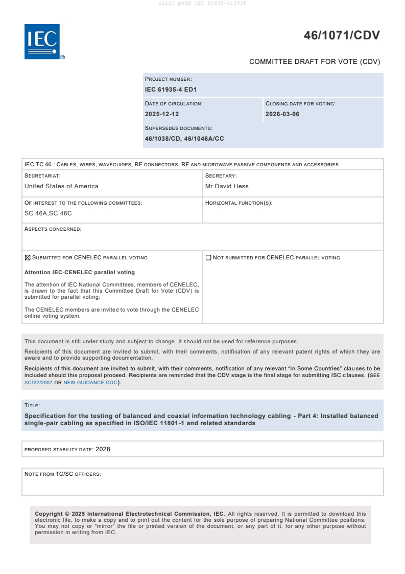
46/1071/CDV
COMMITTEE DRAFT FOR VOTE (CDV)
PROJECT NUMBER:
IEC 61935-4 ED1
DATE OF CIRCULATION: CLOSING DATE FOR VOTING:
2025-12-12 2026-03-06
SUPERSEDES DOCUMENTS:
46/1038/CD, 46/1046A/CC
IEC TC 46 : CABLES, WIRES, WAVEGUIDES, RF CONNECTORS, RF AND MICROWAVE PASSIVE COMPONENTS AND ACCESSORIES
SECRETARIAT: SECRETARY:
United States of America Mr David Hess
OF INTEREST TO THE FOLLOWING COMMITTEES: HORIZONTAL FUNCTION(S):
SC 46A,SC 46C
ASPECTS CONCERNED:
SUBMITTED FOR CENELEC PARALLEL VOTING NOT SUBMITTED FOR CENELEC PARALLEL VOTING
Attention IEC-CENELEC parallel voting
The attention of IEC National Committees, members of CENELEC,
is drawn to the fact that this Committee Draft for Vote (CDV) is
submitted for parallel voting.
The CENELEC members are invited to vote through the CENELEC
online voting system.
This document is still under study and subject to change. It should not be used for reference purposes.
Recipients of this document are invited to submit, with their comments, notification of any relevant patent rights of which t hey are
aware and to provide supporting documentation.
Recipients of this document are invited to submit, with their comments, notification of any relevant “In Some Countries” clau ses to be
included should this proposal proceed. Recipients are reminded that the CDV stage is the final stage for submitting ISC c lauses. (SEE
AC/22/2007 OR NEW GUIDANCE DOC).
TITLE:
Specification for the testing of balanced and coaxial information technology cabling - Part 4: Installed balanced
single-pair cabling as specified in ISO/IEC 11801-1 and related standards
PROPOSED STABILITY DATE: 2028
NOTE FROM TC/SC OFFICERS:
electronic file, to make a copy and to print out the content for the sole purpose of preparing National Committee positions.
You may not copy or "mirror" the file or printed version of the document, or any part of it, for any other purpose without
permission in writing from IEC.
IEC CDV 61935-4 © IEC 2025
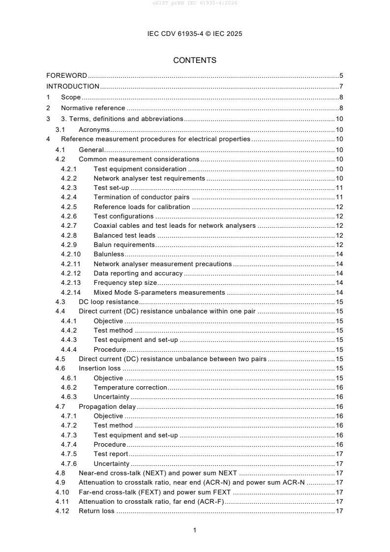
CONTENTS
FOREWORD . 5
INTRODUCTION . 7
1 Scope . 8
2 Normative reference . 8
3 3. Terms, definitions and abbreviations. 10
3.1 Acronyms . 10
4 Reference measurement procedures for electrical properties . 10
4.1 General . 10
4.2 Common measurement considerations . 10
4.2.1 Test equipment consideration . 10
4.2.2 Network analyser test requirements . 10
4.2.3 Test set-up . 11
4.2.4 Termination of conductor pairs . 11
4.2.5 Reference loads for calibration . 12
4.2.6 Test configurations . 12
4.2.7 Coaxial cables and test leads for network analysers . 12
4.2.8 Balanced test leads . 12
4.2.9 Balun requirements. 12
4.2.10 Balunless . 14
4.2.11 Network analyser measurement precautions . 14
4.2.12 Data reporting and accuracy . 14
4.2.13 Frequency step size. 14
4.2.14 Mixed Mode S-parameters measurements . 14
4.3 DC loop resistance. 15
4.4 Direct current (DC) resistance unbalance within one pair . 15
4.4.1 Objective . 15
4.4.2 Test method . 15
4.4.3 Test equipment and set-up . 15
4.4.4 Procedure . 15
4.5 Direct current (DC) resistance unbalance between two pairs . 15
4.6 Insertion loss . 15
4.6.1 Objective . 15
4.6.2 Temperature correction. 16
4.6.3 Uncertainty . 16
4.7 Propagation delay . 16
4.7.1 Objective . 16
4.7.2 Test method . 16
4.7.3 Test equipment and set-up . 16
4.7.4 Procedure . 16
4.7.5 Test report . 17
4.7.6 Uncertainty . 17
4.8 Near-end cross-talk (NEXT) and power sum NEXT . 17
4.9 Attenuation to crosstalk ratio, near end (ACR-N) and power sum ACR-N . 17
4.10 Far-end cross-talk (FEXT) and power sum FEXT . 17
4.11 Attenuation to crosstalk ratio, far end (ACR-F) . 17
4.12 Return loss . 17
IEC CDV 61935-4 © IEC 2025
4.13 PS alien near end crosstalk (PS ANEXT – Exogenous crosstalk) . 17
4.13.1 Objective . 17
4.13.2 Test method . 18
4.13.3 Test equipment and set-up . 18
4.13.4 Procedure . 18
4.14 PS attenuation to alien crosstalk ratio, far end crosstalk (PS AACR-F –
Exogenous crosstalk) . 20
4.14.1 Objective . 20
4.14.2 Test method . 20
4.14.3 Test equipment and set-up . 20
4.14.4 Procedure . 21
4.15 Transverse conversion loss (TCL – unbalance attenuation, near end) . 23
4.15.1 Objective . 23
4.15.2 Uncertainty . 23
4.16 Equal level transverse conversion transfer loss (ELTCTL – unbalance
attenuation, far end). 23
4.16.1 Objective . 23
4.16.2 Uncertainty . 24
4.17 Coupling attenuation . 24
5 Field test measurement requirements for electrical properties . 24
5.1 Introductory remark . 24
5.2 Cabling configurations tested . 24
5.3 Field test measurement requirements . 25
5.3.1 General . 25
5.3.2 Optional field test parameters . 25
5.3.3 Inspection of workmanship and connectivity testing . 25
5.3.4 Propagation delay . 26
5.3.5 Length . 27
5.3.6 Insertion loss . 27
5.3.7 NEXT, power sum NEXT . 28
5.3.8 ACR-N and power sum ACR-N . 28
5.3.9 FEXT, power sum FEXT . 28
5.3.10 ACR-F and power sum ACR-F . 28
5.3.11 Return loss . 28
5.3.12 Direct current (DC) loop resistance . 28
5.3.13 Direct current (DC) resistance unbalance between pairs . 28
5.3.14 Alien crosstalk parameters . 28
5.4 Data reporting and accuracy . 28
5.4.1 General . 28
5.4.2 Detailed results . 29
5.4.3 Summary results . 29
5.4.4 Reporting requirements for power sum alien crosstalk . 30
5.4.5 Consistency checks for field testers . 31
5.4.6 Evaluation of consistency tests . 31
5.4.7 Administration system applicability . 32
5.4.8 Test equipment adapter cords for link testing . 32
5.4.9 User cords and channel testing . 32
6 Field tester measurement accuracy requirements . 32
IEC CDV 61935-4 © IEC 2025
6.1 General . 32
6.2 Measurement accuracy specifications common to level SP-I, SP-II, and level
SP-III field testers . 36
6.3 Accuracy performance requirements for Level SP-I field testers . 36
6.4 Accuracy performance requirements for level SP-II field testers . 38
6.5 Accuracy performance requirements for level SP-III field testers . 41
6.6 Field tester requirements applicable to alien crosstalk measurements . 44
6.7 Accuracy performance requirements for level V field testers . 44
6.8 Accuracy performance requirements for level VI field testers . 44
6.9 Field tester requirements applicable to alien crosstalk measurements . 44
6.10 Procedures for determining field tester parameters . 44
6.11 Measurement error models . 44
6.12 Network analyser measurement comparisons . 45
Annex A (informative) Uncertainty and variability of field test results . 46
A.1 General . 46
A.2 Marginal results reporting . 46
A.3 Nominal accuracy . 46
A.4 Variability in link measurements not included in the measurement accuracy . 47
A.5 Variability in channel measurements . 47
A.6 Field tester accuracy checks . 47
A.6.1 General . 47
A.6.2 Manipulating cords of link adapter . 48
A.6.3 Exchanging adapters to main and remote field tester units . 48
A.6.4 Location of main and remote field tester units . 48
A.6.5 Use of previously characterized links . 48
A.6.6 Use separately characterized links using laboratory equipment . 48
A.6.7 Guidelines for correct installation testing . 48
Bibliography . 50
Figure 1 – Resistor load . 11
Figure A.1 – Source of variability during link testing . 47
Table 1 – Accuracy levels and frequency ranges. 10
Table 2 Test balun performance characteristics (TBD) . 13
Table 3 –Mixed mode S-parameter nomenclature . 15
Table 4 – Estimated uncertainty of TCL measurement . 23
Table 5 – Estimated uncertainty of ELTCTL measurement . 24
Table 6 – Optional field test parameter measurement requirements . 25
Table 7 – Summary of reporting requirements for field test equipment . 30
Table 8 – Minimum reporting requirements for PS ANEXT and PS AACR-F . 31
Table 9 – Informative worst-case propagation delay, DC resistance and length
measurement accuracy values for level SP-I, SP-II, and SP-III instruments . 34
Table 10 – Informative worst-case insertion loss, return loss, TCL, and ELTCTL
measurement accuracy values for Level SP-I test instruments . 34
Table 11 – Informative worst-case insertion loss, return loss, TCL, and ELTCTL
measurement accuracy values for level SP-II test instruments . 35
IEC CDV 61935-4 © IEC 2025
Table 12 – Informative worst-case insertion loss, return loss, TCL, and ELTCTL
measurement accuracy values for level SP-III instruments . 36
Table 13 – Propagation delay, DC resistance and length accuracy performance
specifications for level SP-I, SP-II, and SP-III testers . 36
Table 14 – Level SP-I field tester accuracy performance parameters per IEC guidelines . 37
Table 15 – Level SP-II field tester accuracy performance parameters per IEC
guidelines . 39
Table 16 – Level SP-III field tester accuracy performance parameters per IEC
guidelines . 42
IEC CDV 61935-4 © IEC 2025
INTERNATIONAL ELECTROTECHNICAL COMMISSION
____________
SPECIFICATION FOR THE TESTING OF BALANCED AND
COAXIAL INFORMATION TECHNOLOGY CABLING –
Part 4: Installed balanced single-pair cabling
as specified in ISO/IEC 11801-1 and related standards
FOREWORD
1) The International Electrotechnical Commission (IEC) is a worldwide organization for standardization comprising
all national electrotechnical committees (IEC National Committees). The object of IEC is to promote international
co-operation on all questions concerning standardization in the electrical and electronic fields. To this end and
in addition to other activities, IEC publishes International Standards, Technical Specifications, Technical Reports,
Publicly Available Specifications (PAS) and Guides (hereafter referred to as “IEC Publication(s)”). Their
preparation is entrusted to technical committees; any IEC National Committee interested in the subject dealt with
may participate in this preparatory work. International, governmental and non-governmental organizations liaising
with the IEC also participate in this preparation. IEC collaborates closely with the International Organization for
Standardization (ISO) in accordance with conditions determined by agreement between the two organizations.
2) The formal decisions or agreements of IEC on technical matters express, as nearly as possible, an international
consensus of opinion on the relevant subjects since each technical committee has representation from all
interested IEC National Committees.
3) IEC Publications have the form of recommendations for international use and are accepted by IEC National
Committees in that sense. While all reasonable efforts are made to ensure that the technical content of IEC
Publications is accurate, IEC cannot be held responsible for the way in which they are used or for any
misinterpretation by any end user.
4) In order to promote international uniformity, IEC National Committees undertake to apply IEC Publications
transparently to the maximum extent possible in their national and regional publications. Any divergence between
any IEC Publication and the corresponding national or regional publication shall be clearly indicated in the latter.
5) IEC itself does not provide any attestation of conformity. Independent certification bodies provide conformity
assessment services and, in some areas, access to IEC marks of conformity. IEC is not responsible for any
services carried out by independent certification bodies.
6) All users should ensure that they have the latest edition of this publication.
7) No liability shall attach to IEC or its directors, employees, servants or agents including individual experts and
members of its technical committees and IEC National Committees for any personal injury, property damage or
other damage of any nature whatsoever, whether direct or indirect, or for costs (including legal fees) and
expenses arising out of the publication, use of, or reliance upon, this IEC Publication or any other IEC
Publications.
8) Attention is drawn to the Normative references cited in this publication. Use of the referenced publications is
indispensable for the correct application of this publication.
9) IEC draws attention to the possibility that the implementation of this document may involve the use of (a)
patent(s). IEC takes no position concerning the evidence, validity or applicability of any claimed patent rights in
respect thereof. As of the date of publication of this document, IEC [had/had not] received notice of (a) patent(s),
which may be required to implement this document. However, implementers are cautioned that this may not
represent the latest information, which may be obtained from the patent database available at
https://patents.iec.ch. IEC shall not be held responsible for identifying any or all such patent rights.
IEC 61935-4 has been prepared by IEC technical committee 46: Cables, wires, waveguides, RF
connectors, RF and microwave passive components and accessories. It is an International
Standard.
The text of this International Standard is based on the following documents:
Draft Report on voting
46/XXXX/FDIS 46/XXXX/RVD
Full information on the voting for its approval can be found in the report on voting indicated in
the above table.
IEC CDV 61935-4 © IEC 2025
The language used for the development of this International Standard is English.
This document was drafted in accordance with ISO/IEC Directives, Part 2, and developed in
accordance with ISO/IEC Directives, Part 1 and ISO/IEC Directives, IEC Supplement, available
at www.iec.ch/members_experts/refdocs. The main document types developed by IEC are
described in greater detail at www.iec.ch/publications.
The committee has decided that the contents of this document will remain unchanged until the
stability date indicated on the IEC website under webstore.iec.ch in the data related to the
specific document. At this date, the document will be
• reconfirmed,
• withdrawn, or
• revised.
IEC CDV 61935-4 © IEC 2025
1 INTRODUCTION
2 Telecommunication cabling, once specified uniquely by each telecommunications application,
3 has evolved into a generic cabling system including single-pair cabling systems.
4 Telecommunications applications use the ISO/IEC 11801-1 cabling standard to meet their
5 cabling requirements. Formerly, connectivity tests and visual inspection were deemed sufficient
6 to verify a cabling installation. Users need more comprehensive testing in order to ensure that
7 the link will support telecommunications applications that are designed to operate on the
8 generic cabling system.
9 Transmission performance depends on cable characteristics, connecting hardware, patch cords
10 and cross-connect cabling, the total number of connections and the care with which they are
11 installed and maintained. IEC 61935 (all parts) provides test methods for installed cabling and
12 pre-fabricated cable assemblies. These test methods, where appropriate, are based on those
13 used for components of the cable assembly.
14 This Part 4 contains the test methods required for laboratory testing and testing of balanced
15 single-pair cabling as specified in ISO/IEC 11801-1 and related standards.
16 Since Part 4 often refers back to IEC 61935-1 for further details, the document structure of part
17 4 has been kept the same as IEC 61935-1 to make the document easier to understand and
18 follow.
IEC CDV 61935-4 © IEC 2025
19 SPECIFICATION FOR THE TESTING OF BALANCED AND
20 COAXIAL INFORMATION TECHNOLOGY CABLING –
22 Part 4: Installed balanced single-pair cabling
23 as specified in ISO/IEC 11801-1 and related standards
25 1 Scope
26 This part of IEC 61935 specifies reference measurement procedures for balanced single-pair
27 cabling parameters and the requirements for field tester accuracy to measure cabling
28 parameters identified in ISO/IEC 11801-1. References in this standard to ISO/IEC 11801-1
29 mean ISO/IEC 11801-1 and related standards.
30 This standard is organized as follows:
31 • reference laboratory measurement procedures on cabling topologies are specified in clause
32 4. In some cases, these procedures may be used in the field;
33 • descriptions and requirements for measurements in the field are specified in clause 5;
34 • performance requirements for field testers and procedures to verify performance are
35 specified in clause 6.
36 NOTE 1 This standard does not include tests that are normally performed on cables and connectors separately. Tests
37 performed on cables and connectors are described in IEC 61156-1 and IEC 60512-28-100, respectively.
38 NOTE 2 Users of this standard are advised to consult with applications standards, equipment manufacturers and
39 system integrators to determine the suitability of these requirements for specific networking applications.
40 Wherever possible, cables and connectors used in cable assemblies, even if they are not
41 described in the IEC 61156 or the IEC 63171 series, should be tested separately according to
42 the parameters given in the ISO/IEC 11801 series.
43 This standard is based on cabling with a characteristic impedance of 100 Ω. For cabling with
44 another characteristic impedance, the same principles apply but the measurement system
45 should correspond to the nominal characteristic impedance level unless the intended
46 application references 100 Ohm cabling.
47 Field tester types include certification, qualification and verification test equipment.
48 Certification testing is performed to the requirements of this standard.
49 Qualification testing determines whether the cabling will support certain network applications
50 (e.g. 10BASE-T1L, 100BASE-T1, 1000BASE-T1, 2.5G/5G/10GBASE-T1). Qualification
51 testers do not have traceable accuracy to national standards and only provide confidence
52 that specific applications will work.
53 Verification testers only verify connectivity.
54 2 Normative reference
55 The following documents are referred to in the text in such a way that some or all of their content
56 constitutes requirements of this document. For dated references, only the edition cited applies.
57 For undated references, the latest edition of the referenced document (including any
58 amendments) applies.
59 IEC 60169-22, Radio-frequency connectors – Part 22: R.F. two-pole bayonet coupled
60 connectors for use with shielded balanced cables having twin inner conductors (Type BNO)
IEC CDV 61935-4 © IEC 2025
61 IEC 60512-25-9, Connectors for electronic equipment – Tests and measurements – Part 25-9:
62 Signal integrity tests – Test 25i: Alien crosstalk
63 IEC 60512-28-100, Connectors for electrical and electronic equipment - Tests and
64 measurements - Part 28-100: Signal integrity tests up to 2 000 MHz - Tests 28a to 28g
65 IEC 63171, Series Connectors for electrical and electronic equipment - Shielded or unshielded
66 free and fixed connectors for balanced single-pair data transmission with current-carrying
67 capacity - General requirements and tests
68 IEC 61156-1, Multicore and symmetrical pair/quad cables for digital communications – Part 1:
69 Generic specification
70 IEC TS 61156-1-2, Multicore and symmetrical pair/quad cables for digital communications –
71 Part 1-2: Electrical transmission characteristics and test method of symmetrical pair/quad
72 cables
73 IEC 61156-11, Multicore and symmetrical pair/quad cables for digital communications - Part 11:
74 Symmetrical single-pair cables with transmission characteristics up to 600 MHz - Horizontal
75 floor wiring - Sectional specification
76 IEC 61156-12, Multicore and symmetrical pair/quad cables for digital communications - Part 12:
77 Symmetrical single-pair cables with transmission characteristics up to 600 MHz - Work area
78 wiring - Sectional specification
79 IEC 61156-13, MULTICORE AND SYMMETRICAL PAIR/QUAD CABLES FOR DIGITAL
80 COMMUNICATIONS - Part 13: Symmetrical single-pair cables with transmission characteristics
81 up to 20 MHz - Horizontal floor wiring - Sectional specification
82 IEC 61156-14, MULTICORE AND SYMMETRICAL PAIR/QUAD CABLES FOR DIGITAL
83 COMMUNICATIONS. Part 14: Symmetrical single pair cables with transmission characteristics
84 up to 20MHz. Work area wiring – Sectional specification
85 IEC 61169-15, Radio-frequency connectors - Part 15: Sectional specification - RF coaxial connectors
86 with inner diameter of outer conductor 4,13 mm (0,163 in) with threaded coupling - Characteristic
87 impedance 50 Ω (type SMA)
88 IEC 61935-1, Specification for the testing of balanced and coaxial information technology
89 cabling - Part 1: Installed balanced cabling as specified in ISO/IEC 11801-1 and related
90 standards
91 IEC 61935-1-1, Specification for the testing of balanced and coaxial information technology
92 cabling - Part 1-1: Additional requirements for the measurement of transverse conversion loss
93 and equal level transverse conversion transfer loss
94 IEC 61935-1-2, Specification for the testing of balanced communication cabling in accordance
95 with ISO/IEC 11801-1 – Part 1-2: additional requirements for measurement of resistance
96 unbalance with field test instrumentation
97 IEC 62153-4-9, Metallic communication cable test methods – Part 4-9: Electromagnetic
98 compatibility (EMC) – Coupling attenuation of screened balanced cables, triaxial method
99 IEC 62153-4-11, Metallic communication cable test methods – Part 4-11: Electromagnetic
100 compatibility (EMC) – Coupling attenuation or screening attenuation of patch cords, coaxial
101 cable assemblies, pre-connectorized cables – Absorbing clamp method
IEC CDV 61935-4 © IEC 2025
102 IEC 62153-4-14, Metallic communication cable test methods – Part 4-14: Electromagnetic
103 compatibility (EMC) – Coupling attenuation of cable assemblies (Field conditions) absorbing
104 clamp method
105 ISO/IEC 11801-1, Information technology – Generic cabling for customer premises
106 ISO/IEC 14763-1, Information technology – Implementation and operation of customer premises
107 cabling – Part 1: Administration
108 ISO/IEC 14763-2, Information technology – Implementation and operation of customer
109 premises cabling – Part 2: Planning and installation
110 3 3. Terms, definitions and abbreviations
111 For the purposes of this document, the terms and definitions given in ISO/IEC 11801-1 apply.
112 ISO and IEC maintain terminological databases for use in standardization at the following
113 addresses:
114 • IEC Electropedia: available at https://www.electropedia.org/
115 • ISO Online browsing platform: available at https://www.iso.org/obp
116 1.1 Acronyms
SP single-pair
117 4 Reference measurement procedures for electrical properties
118 4.1 General
119 Clause 4 describes reference measurement procedures for electrical parameters. The
120 measurement procedures are intended to be used in a laboratory environment using laboratory
121 equipment. In some cases, a measurement procedure may also be applicable for field testing.
122 If this is the case, the procedure shall be specifically identified as being suitable for installed
123 cabling and appropriate precautions shall be described.
124 Unless otherwise specified all measurement considerations shall be according to IEC 61935-1,
125 IEC 61935-1-1, and IEC 61935-1-2.
126 Table 1 – Accuracy levels and frequency ranges
Level Frequency range [MHz]
SP-I 0,1 – 20
SP-II 0,1 – 600
SP-III 0,1 – 1 250
127 4.2 Common measurement considerations
128 4.2.1 Test equipment consideration
129 For test equipment considerations refer to IEC 61935-1, IEC 61935-1-1, and IEC 61935-1-2.
130 4.2.2 Network analyser test requirements
131 Usually the input and output terminals of a network analyser are unbalanced. RF transformers
132 with balanced outputs (baluns) can be used with unbalanced signal connections to the network
IEC CDV 61935-4 © IEC 2025
133 analyser. For balunless test adapters, refer to IEC TS 61156-1-2 and IEC 60512-28-100.
134 Balunless test adapters are particularly suitable for mixed mode measurements.
135 4.2.3 Test set-up
136 For test setups refer to IEC 61935-1, IEC 61935-1-1, and IEC 61935-1-2.
137 4.2.4 Termination of conductor pairs
138 During measurement, all conductor pairs of the cabling under test shall be terminated at both
139 ends with impedance matching loads. For pairs under test, this is provided by the test
140 instrumentation at one or both ends. For pairs not under test or not connected to test
141 instrumentation, resistor loads or terminated baluns shall be applied.
142 Unless otherwise specified, the nominal differential mode impedance of the termination shall
143 be 100 . The nominal common mode impedance shall be nominal 50 , unless otherwise
144 specified in the measurement procedure.
145 Resistor loads shall use resistors specified for 0,1 % accuracy at DC and have a return loss
146 of 46 dB up to 100 MHz and 40 dB up to the maximum frequency. For pairs connected to a
147 balun, a common mode load may be implemented by applying a load at the centre tap of the
148 balun. The impedance of the load is equal to the common mode impedance. The common mode
149 impedance is approximately one fourth of the differential mode impedance for this
150 implementation. For pairs connected to resistor loads, common mode load may be implemented
151 by the Y configuration shown in Figure 1 and determined by Equation (1) and Equation (2).
154 Figure 1 – Resistor load
where 𝑅
𝑑𝑖𝑓𝑓
𝑅 =
(1)
155 𝑅 = 50 Ω ± 0,1 %
and 𝑅
𝑑𝑖𝑓𝑓
𝑅 = 𝑅 −
2 𝑐𝑜𝑚𝑚
(2)
156 𝑅 = 25 Ω ±1 %
157 where
158 𝑅 is the differential mode resistance ();
𝑑𝑖𝑓𝑓
159 𝑅 is the common mode resistance ().
𝑐𝑜𝑚𝑚
160 For unscreened cabling, the common mode termination point for the pair is the ends of the wires
161 connected together and to the ground at either end of the cabling. For screened cabling, the
162 common mode termination point is connected to the cable screen and ground at each end of
163 the cabling.
IEC CDV 61935-4 © IEC 2025
164 NOTE Accuracy is dependent on the uses of equivalent calibration techniques.
165 4.2.5 Reference loads for calibration
166 To perform reference plane calibration of the test equipment, the following devices shall be
167 used:
168 • 1-port calibration: a short circuit, an open circuit and an impedance matching reference load;
169 • 2-port calibration: as above, plus a through artefact.
170 The impedance matching termination shall be calibrated against a calibration reference, which
171 shall be a 50 load, traceable to a national reference standard. If the value of the reference
172 load for calibration is 100 , two loads in parallel shall be calibrated against the calibration
173 reference. The reference loads for calibration shall be placed in an SMA type connector
174 according to IEC 61169-15, pin type for cable mounting, in which the load is enclosed on the
175 cable end. A network analyser shall be calibrated, one port full calibration, with the calibration
176 reference. Thereafter, the return loss of the reference loads for calibration shall be measured.
177 The verified return loss shall be 46 dB up to 100 MHz and 40 dB up to the maximum frequency.
178 4.2.6 Test configurations
179 Balanced single-pair cabling configurations according to ISO/IEC 11801-1 shall be supported.
180 4.2.7 Coaxial cables and test leads for network analysers
181 For coaxial cables and test leads for network analysers refer to IEC 61935-1, IEC 61935-1-1,
182 and IEC 61935-1-2.
183 4.2.8 Balanced test leads
184 Balanced test leads and associated connecting hardware to connect between the test
185 equipment and the cable assembly under test shall be taken from components that meet or
186 exceed the requirements for the category of the cable assembly under test. Balanced test leads
187 shall be limited to a length of 50 mm between any test fixtures and the reference plane of the
188 cabling under test. Pairs shall remain twisted between any test fixtures to where connections
189 are made to the DUT, and unscreened balanced test leads shall be separated by 5 mm from
190 any ground plane.
191 4.2.9 Balun requirements
192 Depending on the test set-up, baluns are an optional element that may be required for
193 measurements. In case baluns are used, the following applies:
194 Baluns shall be RFI shielded and shall comply with the requirements given in Table 2 .
IEC CDV 61935-4 © IEC 2025
195 Table 2 Test balun performance characteristics (TBD)
Parameter/class Class SP-I Class SP-II Class SP-III
Frequency range 0,1 to 20 MHz 0,1 to 600 MHz 0,1 to 1250 MHz
Impedance,
50 unbalanced 50 unbalanced 50 unbalanced
a
primary
Impedance,
Matched balanced Matched balanced Matched balanced
secondary
d
Insertion loss ,
3 dB 3 dB 3 dB
maximum
12 dB, 0,1 MHz to
15 MHz
12 dB, 0,1 MHz to
Return loss
15 MHz
12 dB, 0,1 MHz to 20 dB, 15 MHz to
secondary,
20 MHz 600 MHz
20 dB, 15 MHz to
minimum
600 MHz
10 dB, 600 MHz to
1 250 MHz
12 dB, 0,1 MHz to
12 dB, 0,1 MHz to
15 MHz
15 MHz
Return loss,
12 dB, 0,1 MHz to 20 dB, 15 MHz to
b
20 dB, 15 MHz to
common mode ,
20 MHz 600 MHz
600 MHz
minimum
10 dB, 600 MHz to
1 250 MHz
Power rating 0,1 Watt minimum 0,1 Watt minimum 0,1 Watt minimum
60 dB, 0,1 MHz to
400 MHz
60 dB, 0,1 MHz to
400 MHz
Longitudinal
60 dB, 0,1 MHz to 50 dB, 400 MHz to
c
20 MHz 600 MHz
balance , minimum
50 dB, 400 MHz to
600 MHz
40 dB, 600 MHz to
1 250 MHz
60 dB, 0,1 MHz to
400 MHz
60 dB, 0,1 MHz to
400 MHz
Output signal
60 dB, 0,1 MHz to 50 dB, 400 MHz to
c
balance , minimum 20 MHz 600 MHz
50 dB, 400 MHz to
600 MHz
40 dB, 600 MHz to
1 250 MHz
60 dB, 0,1 MHz to
400 MHz
60 dB, 0,1 MHz to
Common mode
400 MHz
60 dB, 0,1 MHz to 50 dB, 400 MHz to
c
rejection ,
20 MHz 600 MHz
50 dB, 400 MHz to
minimum
600 MHz
40 dB, 600 MHz to
1 250 MHz
a
Primary impedance may differ, if necessary to accommodate analyser outputs other
than 50 Ω.
b
Measured either by connecting the balanced output terminals together and measuring
the return loss. The unbalanced balun input terminal shall be terminated by a 50 Ω load.
Or measured at the common-mode port – if available – while terminating the balanced
port for differential and common mode.
c
Measured per ITU-T Recommendations G.117 and O.9.
d
In case separate attenuators are used, they shall be excluded from the insertion loss
measurement.
196 NOTE Proper test for configurations for qualifying tests baluns to the requirements are given in IEC 61935-1, and
197 IEC 61935-1-1.
IEC CDV 61935-4 © IEC 2025
198 4.2.10 Balunless
199 Where balunless techniques are used for measurement, the requirements are provided by
200 IEC TS 61156-1-2, IEC 60512-28-100, and shall be applied to the full frequency range of the
201 test.
202 4.2.11 Network analyser measurement precautions
203 For network analysers measurement precautions refer to IEC 61935-1, IEC 61935-1-1, and IEC
204 61935-1-2.
205 4.2.12 Data reporting and accuracy
206 The measurement uncertainty shall be determined for each test. This shall be calculated by
207 determining the uncertainty from each error source expressed as the resulting spread in the
208 result. The values of the different error sources are based on instrumentation specifications,
209 calculated errors from imperfect calibration loads and measurement experience. The overall
210 estimated measurement uncertainty is calculated as two times the resulting spread coming from
211 the different error sources. The resulting spread is calculated using Equation (3):
2 2 2
𝜎 = √𝜎 + 𝜎 +. . . . . 𝜎
𝑟𝑒𝑠 1 2 𝑛
(3)
212 where to is the spread of the different error sources.
1 n
213 The overall measurement uncertainty is defined as 2𝜎 which is approximately equivalent to a
𝑟𝑒𝑠
214 95 % confidence level. A measurement uncertainty band is determined on both sides of the
215 specified limit.
216 4.2.13 Frequency step size
217 Unless otherwise specified, if the test instrument measures at discrete frequencies, the
218 frequency steps shall be no greater than:
219 • 20 kHz from 0,1 MHz up to 20 MHz
220 • 150 kHz from 20 MHz up to 31,25 MHz;
221 • 250 kHz from 31,25 MHz up to 100 MHz;
222 • 500 kHz from 100 MHz up to 250 MHz;
223 • 1 MHz from 250 MHz up to 600 MHz;
224 • 2 MHz from 600 MHz up to 1 250 MHz.
225 4.2.14 Mixed Mode S-parameters measurements
226 The S-parameters of a mixed mode measurement consis
...