

ASTM F3217-17
(Guide)Standard Guide for Security Fasteners
General Information
- Abstract
SIGNIFICANCE AND USE
4.1 This guide is intended to be informative in terms of the types and uses of security fasteners in detention and corrections facilities. Useful information related to products and types of fasteners, materials in which fasteners are fabricated and other technical information that will give owners, architects, and end users adequate decision making criteria for the selection and application of such fasteners.
SCOPE
1.1 The purpose of this guide is to provide technical information related to understanding the features, types of materials, and benefits of various types of security fasteners and provide guidance in the selection and application of security fasteners in detention and corrections facilities.
1.2 Units—The values stated in inch-pound units are to be regarded as the standard. The values given in parentheses are mathematical conversions to SI units that are provided for information only and are not considered standard.
1.3 This standard does not purport to address all of the safety concerns, if any, associated with its use. It is the responsibility of the user of this standard to establish appropriate safety, health and environmental practices and determine the applicability of regulatory limitations prior to use.
1.4 This international standard was developed in accordance with internationally recognized principles on standardization established in the Decision on Principles for the Development of International Standards, Guides and Recommendations issued by the World Trade Organization Technical Barriers to Trade (TBT) Committee.
- Status
- Published
- Publication Date
- 31-Jan-2017
- Technical Committee
- F33 - Detention and Correctional Facilities
- Drafting Committee
- F33.04 - Detention Hardware
Overview
ASTM F3217-17: Standard Guide for Security Fasteners provides comprehensive guidance on the selection, application, and technical aspects of security fasteners, specifically for use in detention and correctional facilities. Developed by ASTM International, this standard serves as an informative resource for facility owners, architects, and end users, aiming to facilitate informed decision-making when specifying or installing security fasteners. The guide covers the features, material types, benefits, and practical considerations of various security fastener designs, ensuring durability, resistance to tampering, and appropriate performance in high-security environments.
Key Topics
- Types of Security Fasteners: Outlines both non-removable (one-way, blind, pop rivet, drive pin, twist-off head) and removable types (spanner head, pinned head Allen, pinned Torx, Penta Nut, and proprietary designs for higher security).
- Material Selection: Explains material options such as low, medium, and high-carbon steels, stainless steels (18-8, 316, martensitic), and alloy steels. It covers heat treatment methods like case hardening and through-hardening, which impact strength and durability.
- Surface Finishes: Discusses coatings like black phosphate, dip-spin, hot-dipped galvanizing, zinc electroplating, and tin-zinc for improved corrosion resistance and longevity, particularly in challenging environments.
- Head Designs: Details a range of drive and head types, from traditional Phillips and slotted heads to advanced security profiles like Torx, Torx Plus, Key-Rex, McGard Intimidator, Penta-plus, and T-REVX. Each design offers different levels of tamper resistance and tool control.
- Best Practices: Provides recommendations for thread selection (coarse vs fine), use of thread-cutting screws, thread-locking compounds, torque procedures, and maintenance strategies for maximizing fastener performance and security.
Applications
Security fasteners covered by ASTM F3217-17 are essential in situations where unauthorized removal or tampering must be prevented. Typical applications include:
- Detention and Correctional Facilities: Door hardware, window stops, toilet partitions, furnishings, accessories, and light fixtures to prevent tool-free or unauthorized removal.
- Public Infrastructure: Secure signage, fencing, and access panels where security is a concern.
- Commercial and Institutional Settings: Glazing stops, equipment, and fixtures requiring a balance between security and the need for authorized maintenance.
- High-Corrosion Environments: Selection guidance for fasteners exposed to harsh chemicals, humidity, or galvanic corrosion risks, such as those in kitchens, laundries, or coastal facilities.
The guide also emphasizes matching material and finish to the environment-choosing the right stainless steel or coated steel fastener enhances service life and reliability.
Related Standards
Implementation of ASTM F3217-17 may reference or be supported by several related technical standards, including:
- ASME B1.1: Unified Inch Screw Threads, standardizing thread forms and dimensions for compatibility and reliability.
- BS 1580-1: Unified Screw Threads requirement, providing international alignment on thread standards.
- Additional guidance from manufacturer-specific best practices for proprietary fastener designs, installation, and maintenance protocols.
Referencing these related standards ensures comprehensive compliance and promotes the use of globally recognized best practices in security fastener selection and application.
Keywords: ASTM F3217-17, security fasteners, detention facilities, correctional facility hardware, tamper-resistant fasteners, fastener materials, corrosion resistance, fastener head design, high-security installation, international standard, threaded fasteners, maintenance practices.
Frequently Asked Questions
ASTM F3217-17 is a guide published by ASTM International. Its full title is "Standard Guide for Security Fasteners". This standard covers: SIGNIFICANCE AND USE 4.1 This guide is intended to be informative in terms of the types and uses of security fasteners in detention and corrections facilities. Useful information related to products and types of fasteners, materials in which fasteners are fabricated and other technical information that will give owners, architects, and end users adequate decision making criteria for the selection and application of such fasteners. SCOPE 1.1 The purpose of this guide is to provide technical information related to understanding the features, types of materials, and benefits of various types of security fasteners and provide guidance in the selection and application of security fasteners in detention and corrections facilities. 1.2 Units—The values stated in inch-pound units are to be regarded as the standard. The values given in parentheses are mathematical conversions to SI units that are provided for information only and are not considered standard. 1.3 This standard does not purport to address all of the safety concerns, if any, associated with its use. It is the responsibility of the user of this standard to establish appropriate safety, health and environmental practices and determine the applicability of regulatory limitations prior to use. 1.4 This international standard was developed in accordance with internationally recognized principles on standardization established in the Decision on Principles for the Development of International Standards, Guides and Recommendations issued by the World Trade Organization Technical Barriers to Trade (TBT) Committee.
SIGNIFICANCE AND USE 4.1 This guide is intended to be informative in terms of the types and uses of security fasteners in detention and corrections facilities. Useful information related to products and types of fasteners, materials in which fasteners are fabricated and other technical information that will give owners, architects, and end users adequate decision making criteria for the selection and application of such fasteners. SCOPE 1.1 The purpose of this guide is to provide technical information related to understanding the features, types of materials, and benefits of various types of security fasteners and provide guidance in the selection and application of security fasteners in detention and corrections facilities. 1.2 Units—The values stated in inch-pound units are to be regarded as the standard. The values given in parentheses are mathematical conversions to SI units that are provided for information only and are not considered standard. 1.3 This standard does not purport to address all of the safety concerns, if any, associated with its use. It is the responsibility of the user of this standard to establish appropriate safety, health and environmental practices and determine the applicability of regulatory limitations prior to use. 1.4 This international standard was developed in accordance with internationally recognized principles on standardization established in the Decision on Principles for the Development of International Standards, Guides and Recommendations issued by the World Trade Organization Technical Barriers to Trade (TBT) Committee.
ASTM F3217-17 is classified under the following ICS (International Classification for Standards) categories: 21.060.01 - Fasteners in general. The ICS classification helps identify the subject area and facilitates finding related standards.
ASTM F3217-17 is available in PDF format for immediate download after purchase. The document can be added to your cart and obtained through the secure checkout process. Digital delivery ensures instant access to the complete standard document.
Standards Content (Sample)
This international standard was developed in accordance with internationally recognized principles on standardization established in the Decision on Principles for the
Development of International Standards, Guides and Recommendations issued by the World Trade Organization Technical Barriers to Trade (TBT) Committee.
Designation: F3217 − 17
Standard Guide for
Security Fasteners
This standard is issued under the fixed designation F3217; the number immediately following the designation indicates the year of
original adoption or, in the case of revision, the year of last revision. A number in parentheses indicates the year of last reapproval. A
superscript epsilon (´) indicates an editorial change since the last revision or reapproval.
1. Scope 3.1.1 bearing surface, n—area that carries load across the
face of the material.
1.1 The purpose of this guide is to provide technical
3.1.2 blind fastener, n—fastener that can be placed with
information related to understanding the features, types of
materials, and benefits of various types of security fasteners access to only one side of an application (for example, cage ®
nuts, pop rivet ).
and provide guidance in the selection and application of
security fasteners in detention and corrections facilities.
3.1.3 blind side, n—side of the joint that cannot be accessed
(for example, the inside surface of a tubular or box section).
1.2 Units—The values stated in inch-pound units are to be
regarded as the standard. The values given in parentheses are
3.1.4 body, n—inblindfasteners,theportionoftherivetthat
mathematical conversions to SI units that are provided for
expands into the parent material and in threaded fasteners, the
information only and are not considered standard.
unthreaded portion of the fastener under the head.
1.3 This standard does not purport to address all of the
3.1.5 bolt, n—externally threaded fastener that requires a
safety concerns, if any, associated with its use. It is the
nut to secure the fastened joint.
responsibility of the user of this standard to establish appro-
3.1.6 break stem, n—fastener that is installed by gripping
priate safety, health and environmental practices and deter-
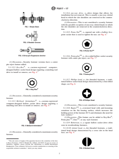
and pulling the end of the mandrel/stem; see Fig. 1.
mine the applicability of regulatory limitations prior to use.
3.1.6.1 Discussion—As installation is completed, the end of
1.4 This international standard was developed in accor-
the stem fractures at the breaker groove and is discarded,
dance with internationally recognized principles on standard-
leaving the head of the stem in the fastener body.
ization established in the Decision on Principles for the
3.1.7 breaker groove, n—weakened groove in the stem or
Development of International Standards, Guides and Recom-
pinofafastenerallowingbreakageatapredeterminedloadand
mendations issued by the World Trade Organization Technical
length; see Fig. 2.
Barriers to Trade (TBT) Committee.
3.1.8 bulbing, v—physicalactionofthefastenerbodyswell-
2. Referenced Documents
ing (expanding radially) against the rear face of the joint when
placed.
2.1 ASME Standard:
3.1.8.1 Discussion—Generally found in break stem fasten-
ASME B1.1 Unified Inch Screw Threads (UN and UNR
ers and threaded inserts.
Thread Form)
2.2 British Standard:
3.1.9 case hardened, adv—heat-treatedfastenerinwhichthe
BS 1580–1 Unified Screw Threads. Screw Threads with
surface is harder than the core.
Diameters ⁄4 in. and Larger. Requirements
3.1.10 chemical-set anchor, n—anchor designed for blind-
hole installations that use a two-component structural grade
3. Terminology
catalyzing resin (usually epoxy) to bind the bolt securely in the
3.1 Definitions:
substrate material.
3.1.11 drive-pin expansion anchor, n—blind-hole expansion
This guide is under the jurisdiction ofASTM Committee F33 on Detention and
anchor usually manufactured from a relatively soft alloy metal
Correctional Facilities and is the direct responsibility of Subcommittee F33.04 on
or plastic, but can also be of steel; see Fig. 3.
Detention Hardware.
3.1.11.1 Discussion—The anchor is expanded into the blind
Current edition approved Feb. 1, 2017. Published August 2017. DOI: 10.1520/
hole by hammering in a supplied pin or nail into the center of
F3217-17.
Available from American Society of Mechanical Engineers (ASME), ASME
the anchor.
International Headquarters, Two Park Ave., New York, NY 10016-5990, http://
3.1.12 drive type, n—the features of a fastener head that
www.asme.org.
Available from British Standards Institution (BSI), 389 Chiswick High Rd.,
allows the fastener to be driven (installed or removed).
London W4 4AL, U.K., http://www.bsigroup.com.
3.1.12.1 Allen head, n—hexagonal hollow socket drive
See thread terminology, types of bolt and screw heads, and types of screw
points for visual reference. design.
Copyright © ASTM International, 100 Barr Harbor Drive, PO Box C700, West Conshohocken, PA 19428-2959. United States
F3217 − 17
3.1.12.4 one-way drive, n—drive design that allows for
installation but not removal. This is usually a one-way slotted
head in which the slot shoulders are removed in the counter-
clockwise direction.
(1) Discussion—This is not considered a security fastener
with the possible exception of one-way slotted heads in which
FIG. 1 Break Stem
the slot shoulders are removed in the counterclockwise direc-
tion.
TM
3.1.12.5 Penta Nut ,n—tapered nut with a hollow five-
point socket that is used to tighten the nut; see Fig. 6.
FIG. 2 Breaker Groove
TM
FIG. 6 Penta Nut
TM
FIG. 3 Drive-pin Expansion Anchor
3.1.12.6 Penta-plus ,n—five-sided hollow socket security
fastener with center pin reject; see Fig. 7.
(1) Discussion—Security fastener versions have a center
pin reject feature added. ®
3.1.12.2 Key-Rex,n—custom-registered computer-
designed hollow socket head design requiring a matching tool
drive to install or remove; see Fig. 4.
TM
FIG. 7 Penta-plus
3.1.12.7 Phillips head, n—for threaded fasteners, a tradi-
tional hollow socket head design characterized by a four-lobed
shape; see Fig. 8. ®
FIG. 4 Key-Rex
(1) Discussion—Generallyconsideredamaximumsecurity
fastener.
FIG. 8 Phillips Head ®
3.1.12.3 McGard Intimidator ,n—custom-registered
computer-designed hollow socket drive design requiring a
(1) Discussion—This is not considered a security fastener.
matching tool drive to install or remove; see Fig. 5.
TM
3.1.12.8 Raptor ,n—oversized head with anti-loosening
serrations on the flat bearing surface, which increases the
holding power of the fastener 20 % and eliminates the need for
lock washers. ®
(1) Discussion—This feature can be added to Key-Rex ,
TM TM
Penta-plus , Zero , or any style fastener.
3.1.12.9 Robertson, n—a square hollow socket drive often ®
seen in woodworking fasteners.
FIG. 5 McGard Intimidator
3.1.12.10 slotted head, n—for threaded fasteners, a tradi-
tional head design characterized by a cross slot in the head
(1) Discussion—Generallyconsideredamaximumsecurity
face; see Fig. 9.
fastener.
The sole source of supply of the apparatus known to the committee at this time
is Bryce Fasteners, 1230 N. Mondel Dr., Gilbert, AZ 85233. If you are aware of
alternative suppliers, please provide this information to ASTM International
Headquarters.Your comments will receive careful consideration at a meeting of the
FIG. 9 Slotted Head
responsible technical committee, which you may attend.
F3217 − 17
3.1.12.11 spanner head, n—for threaded fasteners, one with
a head design characterized by horizontally opposed notches in
the head circumference or round recesses within the head face;
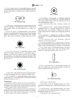
see Fig. 10. ®
FIG. 13 T-REVX
3.1.13 endurance limit/strength, n—maximum alternative
stress that a fastener can withstand for a specified number of
stress cycles without failure. This is not normally an issue in
FIG. 10 Spanner Head
correctional/detention projects.
3.1.13.1 Discussion—See static breaking strengths (in
pounds).
(1) Discussion—Suchdesignsarenotespeciallysecureand
tools for inserting or removing these types of fasteners are
3.1.14 expansion anchor, n—anchor designed for blind-hole
easily broken. They are often referred to as “snake eye”
installations that use a specially designed sleeve, wedge or
fasteners.
other device that, as the fastener is tightened, the sleeve or
3.1.12.12 Torx head, n—multi-lobed hollow socket fastener wedge expands into the available space locking the fastener in
bit design as patented and licensed by Camcar Textron and the place.
design is characterized by a six-lobed shape with rounded
3.1.15 hardening, v—changing the strength or durability
lobes. The security version has an added center pin; see Fig.
characteristics of a fastener through heat treatment or work
11.
hardening.
3.1.15.1 Discussion—See case hardening, induction
hardening, and through hardening.
3.1.16 head form/head style, n—characteristics of the fas-
tener head and head styles include button, pan, truss, hex, hex
flange, socket head large flange, low profile, and countersunk.
3.1.16.1 button head, n—for threaded fasteners, one with a
FIG. 11 Torx Head
low, rounded top surface and a large, flat bearing surface;
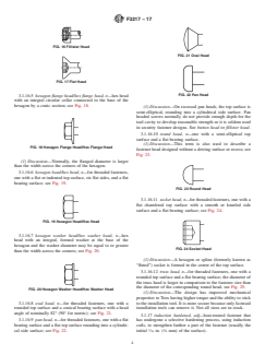
similar to a round head machine screw; see Fig. 14.
3.1.12.13 Torx plus head, n—multi-lobed hollow socket
fastener bit design characterized by a six-pointed shape as
patented and licensed by Camcar Textron and the design
characterized by a six-lobed shape with truncated lobes. The
securityversionisafive-lobedversionthathasanaddedcenter
pin; see Fig. 12.
FIG. 14 Button Head
3.1.16.2 countersunk head, n—for threaded fasteners, one
with a level surface and a conical bearing surface; available in
various nominal head angles; see Fig. 15.
FIG. 12 Torx Plus Head
(1) Discussion—This design has better mechanical proper-
ties than the standard Torx but is limited in available sizes. ®
3.1.12.14 T-REVX ,n—multi-lobed hollow socket fastener
characterized by a seven-point shape as patented and licensed
FIG. 15 Countersunk Head
by Bryce Fastener; see Fig. 13.
(1) Discussion—See flat head.
The Torx head is covered by a patent. If you are aware of an alternative(s) to
thepatenteditem,pleaseattachtoyourballotreturnadescriptionofthealternatives. 3.1.16.3 fillister head—for threaded fasteners, one with a
All suggestions will be considered by the committee. If alternatives are identified,
roundedtop,cylindricalsides,andflatbearingsurface;seeFig.
the committee shall reconsider whether the patented item is necessary. The
16.
committee, in making its decision, shall follow Regulation 15.
7 ®
The T-REVX is covered by a patent. If you are aware of an alternative(s) to
3.1.16.4 flat head, n—for threaded fasteners, one with a
thepatenteditem,pleaseattachtoyourballotreturnadescriptionofthealternatives.
levelsurfaceandaconicalbearingsurface;availableinvarious
All suggestions will be considered by the committee. If alternatives are identified,
nominal head angles; see Fig. 17.
the committee shall reconsider whether the patented item is necessary. The
committee, in making its decision, shall follow Regulation 15. (1) Discussion—See countersunk head.
F3217 − 17
FIG. 16 Fillister Head
FIG. 21 Oval Head
FIG. 17 Flat Head
FIG. 22 Pan Head
3.1.16.5 hexagon flange head/hex flange head, n—hex head
with an integral circular collar connected to the base of the
hexagon by a conic section; see Fig. 18.
(1) Discussion—On recessed pan heads, the top surface is
semi-elliptical, rounding into a cylindrical side surface. Pan
headed screws normally do not provide enough depth for the
tool cavity to develop reasonable strength so it is seldom used
in security fastener designs. See button head or fillister head.
3.1.16.10 round head, n—one with a semi-elliptical top
surface and a flat bearing surface.
(1) Discussion—This term is also used to describe a
FIG. 18 Hexagon Flange Head/Hex Flange Head
fastener head designed without a driving surface or recess; see
Fig. 23.
(1) Discussion—Normally, the flanged diameter is larger
than the width across the corners of the hexagon.
3.1.16.6 hexagon head/hex head, n—for threaded fasteners,
one with a flat or indented top surface, six flat sides, and a flat
bearing surface; see Fig. 19.
FIG. 23 Round Head
3.1.16.11 socket head, n—for threaded fasteners, one with a
flat chamfered top surface with a smooth or knurled side
surface and a flat bearing surface; see Fig. 24.
FIG. 19 Hexagon Head/Hex Head
3.1.16.7 hexagon washer head/hex washer head, n—hex
head with an integral, formed washer at the base of the
hexagon and the washer diameter may be equal to or greater
FIG. 24 Socket Head
than the width across the corners; see Fig. 20.
(1) Discussion—A hexagon or spline (formerly known as
“fluted”) socket is formed in the center of the top surface.
3.1.16.12 truss head, n—for threaded fasteners, one with a
rounded top surface and a flat bearing surface; the diameter of
the truss head is larger in comparison to the fastener size than
the diameter of the corresponding round head; see Fig. 25.
FIG. 20 Hexagon Washer Head/Hex Washer Head
(1) Discussion—The design has improved mechanical
properties to Torx having higher torque and the ability to stick
3.1.16.8 oval head, n—for threaded fasteners, one with a to the installation tool. It is more secure because only licensed
rounded top surface and a conical bearing surface with a head installation tools can remove it. Not all sizes are in stock.
angle of nominally 82° (90° for metric); see Fig. 21.
3.1.17 induction hardened, adj—heat-treated fastener that
3.1.16.9 pan head, n—for threaded fasteners, one with a flat has undergone a selective hardening process, using induction
bearing surface and a flat top surface rounding into a cylindri- coils, to strengthen further a part of the fastener (usually the
1 1
cal side surface; see Fig. 22. initial ⁄16 in. ( ⁄6 mm) of the surface).
F3217 − 17
FIG. 28 Pinned Head Fastener
3.1.25 proof load, n—amount of load a fastener can with-
FIG. 25 Truss Head
stand before permanent plastic deformation will occur.
3.1.25.1 Discussion—See yield strength.
3.1.18 length of engagement, n—length of full-sized fas-
3.1.26 pull out, n—minimum force required to remove a
tener threads that engage in the nut material.
fastener axially away from the parent material.
3.1.18.1 Discussion—The length of the lead thread is not
3.1.27 pulling force, n—axial force the tool applies during
counted in the length of engagement since its reduced size
the installation of rivets.
minimizes any performance benefits. The length of engage-
3.1.28 right-hand thread, n—standard thread design; winds
ment is usually expressed in relationship to the nominal
counter-clockwise in a receding direction; see Fig. 29.
diameter of the screw (for example, 2 to 2 ⁄2 diameters of
engagement).
3.1.19 left-hand thread, n—standard thread design; winds
clockwise in a receding direction; see Fig. 26.
FIG. 29 Right-hand Thread
3.1.29 Rockwell Hardness Test, n—test designed to measure
the hardness of the fastener based on an alphanumeric scale.
FIG. 26 Left-hand Thread
3.1.29.1 Discussion—The higher the number, the harder the
fastener. Rockwell tests are used to test for decarburization and
3.1.20 maximum torque, n—see ultimate torque. carburization and determine the amount of resistance to per-
manent deformation during the testing procedure. They also
3.1.21 minimum torque, n—see torque (recommended).
ensure that heat treating was performed to specification.
3.1.22 passivation/passivated, n/v—process to remove con-
3.1.30 screw, n—externally threaded fastener that does not
taminants from the surface of stainless steel.
require a nut to secure the fastened joint.
3.1.22.1 Discussion—Alsoanameforthechromaticprocess
applied to some metallic finishes to enhance corrosion resis- 3.1.31 seating torque (recommended), n—recommended
tance.
value in inch-pounds or foot-pounds to which a particular
threaded fastener should be tightened.
3.1.23 pilot point, n—cylindrical point with a diameter
somewhat smaller than the shank diameter, which aids align- 3.1.32 shank, n—portion of a fastener under the head; see
ment and starting during installation; see Fig. 27. Fig. 30.
FIG. 30 Shank
FIG. 27 Pilot Point
3.1.33 shear, n—force that tends to divide an object along a
plane parallel to the opposing stresses.
3.1.23.1 Discussion—Also called a “dog point” (applies
3.1.33.1 Discussion—Usually measured in lbf/in. , psi,
normally to set screws).
MPa, or N/m .
3.1.24 pinned head fastener, n—hollow socket drive design
3.1.34 shear strength, n—resistance to transverse loading.
enhancement in which a central pin is introduced into the
Maximum load that can be withstood prior to rupture when
design to render the fastener less prone to removal using
loads are applied normal to the fastener’s axis.
makeshift tools by eliminating adequate bearing surface in
3.1.34.1 Discussion—Usually defined as a force in Newtons
which to exert force to the fastener; see Fig. 28.
(N) or foot-pounds (lbf).
3.1.24.1 Discussion—Pinned Allen, pinned Torx,and pinned
Torx Plus are examples of such designs common to the 3.1.35 stem, n—part of a break stem fastener that is retained
detention and correctional industry. within the body.
F3217 − 17
3.1.35.1 Discussion—Also known as the mandrel. 3.1.46 ultimate tensile stress, n—peak longitudinal load
before rupture.
3.1.36 stem retention, n—forcerequiredtoseparatethestem
3.1.46.1 Discussion—Usually measured in lbf/in. , psi,
from the body of an uninstalled break stem fastener.
MPa, or N/m .
3.1.37 tensile strength, n—amount of longitudinal load/
3.1.47 ultimate torque, n—amount of force at which a
elongation a fastener can withstand without failure of the
threaded fastener begins to strip or otherwise fail in a joint or
fastener or joint.
strip the threads of an insert or nut.
3.1.37.1 Discussion—Measured in lbf/in. , psi, MPa, or
3.1.47.1 Discussion—For threaded inserts and clinch
N/m . See ultimate tensile stress.
fasteners, it may also be referred to as supported torque.
3.1.38 thermoset, n—polymer characterized by extreme
3.1.48 Unified Coarse Thread (UNC), n—inch thread form
stiffness and undergoes a chemical change when heated. Once
(60°) standard defined by ANSI/ASME.
molded and cured “set” (hard and solid) the material cannot be
3.1.48.1 Discussion—Usually used in reference to machine
melted and re-molded.
screws. It is covered by ASME B1.1 and British Standard BS
3.1.38.1 Discussion—Normally used on chemical set an-
1580.
chors.
3.1.49 Unified Fine Threat, UNF, n—imperial thread form
3.1.39 thread-cutting shank, n—portion of a screw of bolt
standard defined by ANSI/AMSE.
with longitudinal cut(s) in the tip of the threaded portion
3.1.49.1 Discussion—Usually used in reference to machine
intended to cut or chase threads in untapped material or clean
screws. It is covered by ASME B1.1 and British Standard BS
out threads in the nut or tapped receiver (most common use in
1580.
this guide); see Fig. 31.
3.1.50 washer face, n—circular boss on the bearing surface
of a cap screw or nut.
3.1.50.1 Discussion—Theonlyboltthathasawasherfaceis
the heavy hex structural bolt; see Fig. 33.
FIG. 31 Thread-cutting Shank
3.1.40 thread engagement, n—amountofthreadtooththatis
filled by the application material.
3.1.40.1 Discussion—This measurement is usually ex-
FIG. 33 Washer Face
pressed as a percentage and is used to determine optimal hole
size.
3.1.41 threaded fastener, n—any screw/bolt (external
3.1.51 wedge anchor, n—anchor designed for blind-hole
threads), nut (internal threads), or combination with machine/
installations that use a specially designed wedge or spade that,
standard or engineered threads and does not include custom
as the fastener is tightened, the wedge (usually a soft alloy)
stamped or formed components with internal or external
expands into the available space locking the fastener in place.
threads or both.
3.1.51.1 Discussion—Similar to expansion anchors.
3.1.42 threaded insert, n—fastener that provides load-
3.1.52 work hardening/cold working, v—increase in metal
bearing threads in materials too thin or brittle to accept regular
hardness that is the result of forming processes such as
standard fasteners.
elongation, rolling, heading, and so forth.
3.1.52.1 Discussion—This is particular pronounced in
3.1.43 through hardened, adv—heat-treated fastener with
steels, copper, and aluminum alloys.
uniform hardness from the surface to the core.
3.1.53 yield strength, n—measure of the resistance of mate-
3.1.44 torsion, n—twisting force applied to a fastener.
rial to plastic deformation. This relates to the point where a
3.1.45 twist-off head, n—head design that incorporates a
fastener will yield before it reaches a point it will not return to
weak shear plane whereby a torque limit is reached and the
its original state.
head shears off leaving a cone or bulb rendering the fastener
3.1.53.1 Discussion—When a fastener is stretched, yield
non-removable; see Fig. 32.
strength is the point at which the fastener will not return to its
original length following testing. It is measured in terms of psi
or MPa.
4. Significance and Use
4.1 This guide is intended to be informative in terms of the
typesandusesofsecurityfastenersindetentionandcorrections
facilities. Useful information related to products and types of
fasteners, materials in which fasteners are fabricated and other
FIG. 32 Twist-off Head
technical information that will give owners, architects, and end
F3217 − 17
users adequate decision making criteria for the selection and resilient to shock. The result is a tough and hard fastener,
application of such fasteners. especiallyeffectiveinself-tappingandself-drillingscrews.The
overall strength is not much different than a mild steel fastener.
5. Materials
This age-old process was used to improve the performance of
Roman and Japanese swords.
5.1 Steel:
5.3.2 Through-Hardened Steel—High-carbon (1035 and
5.1.1 Low-Carbon Steel—Low-carbonsteel(C1006,C1008,
1038) and alloy steels (4037 and 8740) have enough internal
C1010) has low yield strength making it undesirable for
carbon that, when brought to temperature, the carbon changes
security fasteners and is also known as mild steel.
the structure of the whole fastener hardening it all the way
5.1.2 Case-Hardening Steels—C1018 and C1022 are low
through, not at just the surface. This heat-treating method
carbon steels used for self-threading and self-drilling screws.
requires a fast quench (to retain this transformation) followed
Withaspecialheat-treatingmethodcalledcasehardening,they
by tempering to mitigate its brittleness and make the fastener
can be made to have an extremely hard skin and a ductile
tougher. Through hardening markedly increases the overall
internal core. This creates an inexpensive effective self-taping
strengthofthefastener.Medium-carbonsteelrisesfrom60000
fastener.
to 120 000 psi (413.68 to 827.37 MPa), high carbon to 150 000
5.1.3 Medium-Carbon 1035 Steel Having 0.35 % Carbon—
psi (1034.21 MPa), and alloy steels to 150 000 to 180 000 psi
This is the steel normally used for Grade 5 bolts.This steel can
(1034.21 to 1241.05 MPa). Low-carbon steels (1002, 1008,
be through hardened and attain 120 000- to 125 000-psi
and 1010) cannot be through hardened, as there is not enough
(827.37- to 861.84-MPa) breaking strength.
internal carbon to make them transform.
5.1.4 High-Carbon 1038 Steel Having 0.38 % Carbon—
This steel is normally used for Grade 8 bolts. It can be through
6. Finish
hardened and obtain 150 000-psi (1034.21-MPa) breaking
strength.
6.1 Black Phosphate—This is an historical coating origi-
5.1.5 Alloy Steel—Alloy steels include 4037 and 8740.
nally used on socket screws and has been replaced by black
These are steels with 0.37 to 0.40 % carbon alloyed with other
oxide. Both of which are poor coatings for the corrections
materials to make them tougher (represented by the call out 40
industry as they easily rust.
and 87). These are generally used in socket-type screws. They
6.2 Dip-Spin Coatings—This is a new method of coating
are more ductile than high-carbon steels. They can be heat
steel fasteners commonly used in the auto industry. It is
treated to obtain 150 000 to 180 000 psi (1034.21 to 1241.05
environmentally friendly and much more anticorrosive than
MPa) breaking strength.
other platings. Thickness ranges from 2 to 3 mils. Since there
5.2 Stainless Steel:
are many brand names and formulas, it may be best specified
5.2.1 Austenitic Stainless Steel—Most well-known and used
by its salt-spray effectiveness. A 500 salt-spray resistance is
in the construction industry and includes the two most preva-
easily obtained by most. This is also very effective for
lent Types 18-8 and 316. Austenitic steels make up over 70 %
high-carbon steel fasteners as it does not create hydrogen
of total stainless steel production.
embrittlement. It is also paintable.
5.2.1.1 18-8—Types 305, 304, 303, 302, and 301 fall under
6.3 Hot-Dipped Galvanizing—This is a good choice for
the 18-8 heading. These all have the approximate composition
exterior applications in larger sizes. Hot-dipped galvanizing is
of 18 % chromium and 8 % nickel and are similarly anticor-
a rather “thick” coating and as such can be problematic on
rosive. They may also be referred to as A2 stainless. After
smaller sizes and fine threads. This coating is usually found on
manufacture, they usually obtain a strength of 90 000 psi
fasteners used on fencing and structural steel in marine
(620.52 MPa). They are stronger than mild steels but not as
environments.
hard as medium carbon steels.
6.4 Zinc Electroplating—Thischoiceoffersamilddegreeof
5.2.1.2 Type 316—Also known as 18/10 for its composition
corrosion resistance (80 to 90 salt-spray hours) but should only
of 18 % chromium and 10 % nickel. It may also be referred to
be specified for indoor applications. In most cases, some form
as marine-grade stainless primarily for its increased resistance
of chromate is added to increase corrosion resistance. It is the
to corrosion. It is often used in cutlery and high-quality
industry standard for steel fasteners but has some environmen-
cookware. Strength is similar to 18-8 stainless steels.
tal problems.
5.2.2 Martensitic Stainless Steel—Martensitic stainless
steels (usually called 410) are not as corrosion resistant as the
6.5 Tin zinc is a combination of two metals and can obtain
other two classes but are extremely strong and tough as well as
400 to 500 salt-spray resistance. This special order plating has
being highly machinable and hardenable by heat treatment.
a shiny color.
This rare form of stainless is used only for self-threading
screws and self-drilling screws. 7. Fastener Types
5.3 Heat-Treated Steel: 7.1 Non-Removable—These are fasteners that by their de-
5.3.1 Case-Hardened Steel—Case hardening is a method of sign are intended upon installation to have no means of
heat treating 1018 and 1022 steel in a “high-carbon atmo- removal. Examples include one-way designs, blind fasteners
sphere.” The carbon invades the skin of the fastener 0.001 to (pop rivets), drive-pin fasteners, twist-off head fasteners, and
0.005deepmakingthatpartextremelyhard,sometimesashard other proprietary designs. Such fasteners require the destruc-
as HRC 60. The internal part is left unaffected making it tionoftheheadwithasaw,grinder,ortorchtoremovetheitem
F3217 − 17
fastened. These types are excellent for items that need to be 8.1.2 Removable Security Fastener Head Options for
secured and left alone. Examples include: Consideration—The selection of the right fastener also de-
7.1.1 Toilet partitions, pends on similar factors including the size of the fastener,
7.1.2 Detention furnishings, spacing, level of security, required load-carrying capacity, and
7.1.3 Detention accessories, corrosionresistance.Itisveryadvantageoustoselectafastener
7.1.4 Detention hollow metal to nonmetallic substrates tooling solution that requires maintenance personnel to have to
where welding is not an option, and carry the least sizes and types of tools.
7.1.5 Door trim hardware (weather stripping and thresh- 8.1.2.1 Low-security uses include spanner head designs.
olds).
However, the utility of such uses may be impractical because
of the additional tools required to affect maintenance.
7.2 Removable—These are fasteners that by their design are
8.1.2.2 Medium-security uses are generally the domain of
intended to be installed and removed using special tools. For
pinned Torx, pinned hex, or pinned Torx-Plus designs. This
security fasteners, this includes spanner head, pinned head
fastener type dominates the detention and corrections industry
Allen, pinned head Torx, pinned head Torx-Plus, McGard, and
today because they are widely recognized, available, and the
others. In these locations, regular access for maintenance or
cost per unit is reasonable. However, with the tool bits
potential access for replacement necessitates the application of
becoming generally available through hardware and home
removable fasteners. In security applications, a reasonably
imp
...