

ASTM F3694-24
(Guide)Standard Guide for Towing and Anchoring Oil Booms
General Information
- Abstract
SIGNIFICANCE AND USE
4.1 This guide is intended to assist oil spill responders during activities involving the towing and anchoring of oil boom.
4.2 The effective and safe operations involving the towing and anchoring of booms is dependent on many factors that impact the outcome. These include the environmental conditions, personnel training and performance, and equipment selection. Warning—During boom towing and anchoring evolutions, large forces can be generated by environmental conditions or the vessels involved. Always ensure lines and hardware are properly sized and good seamanship practices are followed. Lines that are under tension could possibly break (part) and care should be taken to avoid a position where the recoil could cause injury. Avoid handling lines under tension close to bitts, cleats, or towing posts and always maintain a safe distance from your hands. Before commencing operations, conduct an on-site safety meeting to discuss the work, working conditions, and potential hazards that may be encountered and safe work practices.
SCOPE
1.1 In this guide, considerations to be used when selecting, towing, and anchoring oil booms for control during oil spill events are addressed.
1.2 In this guide, the user is provided methods to tow and anchor oil booms most effectively for best effectiveness and safety.
1.3 It is the user’s responsibility to determine if the boom, vessels, hardware, and accessories selected are suitable for the task and the environmental conditions.
1.4 Units—The values stated in SI units are to be regarded as standard. No other units of measurement are included in this standard.
1.5 This standard does not purport to address all of the safety concerns, if any, associated with its use. It is the responsibility of the user of this standard to establish appropriate safety, health, and environmental practices and determine the applicability of regulatory limitations prior to use.
1.6 This international standard was developed in accordance with internationally recognized principles on standardization established in the Decision on Principles for the Development of International Standards, Guides and Recommendations issued by the World Trade Organization Technical Barriers to Trade (TBT) Committee.
- Status
- Published
- Publication Date
- 29-Feb-2024
- Technical Committee
- F20 - Hazardous Substances and Oil Spill Response
- Drafting Committee
- F20.11 - Control
Overview
ASTM F3694-24: Standard Guide for Towing and Anchoring Oil Booms provides comprehensive guidance for oil spill responders on the selection, towing, and anchoring of oil spill containment booms. Developed by ASTM International, this standard supports effective and safe oil spill response operations, especially in varying environmental conditions. By following ASTM F3694-24, responders can make informed decisions regarding equipment and deployment practices, ultimately reducing the risk of spill spread and improving ecological protection during emergency situations.
Key Topics
Selection of Oil Booms
Outlines considerations for choosing appropriate oil boom types based on environmental conditions, waterbody classifications, and expected spill characteristics.Towing Methods and Safety
Details best practices for towing oil containment booms, including vessel configuration, line selection, and boom deployment procedures. Emphasizes the importance of properly sized lines, safe work practices, and thorough safety meetings before operations begin.Anchoring Techniques
Provides methods for securely anchoring booms in various aquatic environments, taking into account factors such as seabed type, current direction, and water depth. Covers the use of diverse anchoring systems, including anchors, pilings, and shoreline posts.Environmental and Operational Factors
Addresses the impact of environmental conditions (e.g., wind, current, wave action) and highlights the necessity of personnel training and equipment suitability.Boom Configuration and Failures
Discusses common boom layouts (e.g., U, V, J, and chevron configurations) for containment and diversion, and identifies typical failure modes such as entrainment, splash over, and submergence.
Applications
ASTM F3694-24 is vital for organizations and personnel involved in oil spill response and environmental protection. Common applications include:
Oil Spill Containment
Guiding the deployment and operation of floating oil containment booms in coastal, lake, and river scenarios. Ensures quick response to contain and recover spilled oil efficiently.Boom Towing and Anchoring Operations
Informing responders on the safe towing of booms using appropriately rated vessels, tow lines, and connectors. Facilitates the secure placement of booms to maximize containment and minimize environmental impact.Environmental Safety and Compliance
Assisting responders in establishing safe work practices and adherence to international standards, supporting regulatory compliance and effective hazard mitigation.Training and Preparedness
Serving as an educational resource for personnel training on oil boom deployment, maintenance, and safety protocols, ensuring readiness before spill events.
Related Standards
Several referenced ASTM standards support the application of ASTM F3694-24:
- ASTM F625/F625M - Practice for Classifying Water Bodies for Spill Control Systems
- ASTM F818 - Terminology Relating to Spill Response Booms and Barriers
- ASTM F962 - Specification for Oil Spill Response Boom Connection: Z-Connector
- ASTM F1523 - Guide for Selection of Booms in Accordance With Water Body Classifications
- ASTM F1657/F1657M - Practice for Emergency Joining of Booms with Incompatible Connectors
- ASTM F2438 - Specification for Oil Spill Response Boom Connection: Slide Connector
Practical Value
ASTM F3694-24 empowers emergency responders and environmental protection agencies to implement reliable oil spill containment strategies. By following this standard, users enhance safety, increase spill response efficiency, and ensure the effective use of oil booms and related equipment under real-world conditions. Its guidance bridges the gap between technical requirements and practical field operations, supporting both regulatory compliance and the protection of sensitive aquatic environments.
Keywords: oil boom towing, oil boom anchoring, oil spill response, oil containment, ASTM F3694-24, boom deployment, environmental protection standards
Frequently Asked Questions
ASTM F3694-24 is a guide published by ASTM International. Its full title is "Standard Guide for Towing and Anchoring Oil Booms". This standard covers: SIGNIFICANCE AND USE 4.1 This guide is intended to assist oil spill responders during activities involving the towing and anchoring of oil boom. 4.2 The effective and safe operations involving the towing and anchoring of booms is dependent on many factors that impact the outcome. These include the environmental conditions, personnel training and performance, and equipment selection. Warning—During boom towing and anchoring evolutions, large forces can be generated by environmental conditions or the vessels involved. Always ensure lines and hardware are properly sized and good seamanship practices are followed. Lines that are under tension could possibly break (part) and care should be taken to avoid a position where the recoil could cause injury. Avoid handling lines under tension close to bitts, cleats, or towing posts and always maintain a safe distance from your hands. Before commencing operations, conduct an on-site safety meeting to discuss the work, working conditions, and potential hazards that may be encountered and safe work practices. SCOPE 1.1 In this guide, considerations to be used when selecting, towing, and anchoring oil booms for control during oil spill events are addressed. 1.2 In this guide, the user is provided methods to tow and anchor oil booms most effectively for best effectiveness and safety. 1.3 It is the user’s responsibility to determine if the boom, vessels, hardware, and accessories selected are suitable for the task and the environmental conditions. 1.4 Units—The values stated in SI units are to be regarded as standard. No other units of measurement are included in this standard. 1.5 This standard does not purport to address all of the safety concerns, if any, associated with its use. It is the responsibility of the user of this standard to establish appropriate safety, health, and environmental practices and determine the applicability of regulatory limitations prior to use. 1.6 This international standard was developed in accordance with internationally recognized principles on standardization established in the Decision on Principles for the Development of International Standards, Guides and Recommendations issued by the World Trade Organization Technical Barriers to Trade (TBT) Committee.
SIGNIFICANCE AND USE 4.1 This guide is intended to assist oil spill responders during activities involving the towing and anchoring of oil boom. 4.2 The effective and safe operations involving the towing and anchoring of booms is dependent on many factors that impact the outcome. These include the environmental conditions, personnel training and performance, and equipment selection. Warning—During boom towing and anchoring evolutions, large forces can be generated by environmental conditions or the vessels involved. Always ensure lines and hardware are properly sized and good seamanship practices are followed. Lines that are under tension could possibly break (part) and care should be taken to avoid a position where the recoil could cause injury. Avoid handling lines under tension close to bitts, cleats, or towing posts and always maintain a safe distance from your hands. Before commencing operations, conduct an on-site safety meeting to discuss the work, working conditions, and potential hazards that may be encountered and safe work practices. SCOPE 1.1 In this guide, considerations to be used when selecting, towing, and anchoring oil booms for control during oil spill events are addressed. 1.2 In this guide, the user is provided methods to tow and anchor oil booms most effectively for best effectiveness and safety. 1.3 It is the user’s responsibility to determine if the boom, vessels, hardware, and accessories selected are suitable for the task and the environmental conditions. 1.4 Units—The values stated in SI units are to be regarded as standard. No other units of measurement are included in this standard. 1.5 This standard does not purport to address all of the safety concerns, if any, associated with its use. It is the responsibility of the user of this standard to establish appropriate safety, health, and environmental practices and determine the applicability of regulatory limitations prior to use. 1.6 This international standard was developed in accordance with internationally recognized principles on standardization established in the Decision on Principles for the Development of International Standards, Guides and Recommendations issued by the World Trade Organization Technical Barriers to Trade (TBT) Committee.
ASTM F3694-24 is available in PDF format for immediate download after purchase. The document can be added to your cart and obtained through the secure checkout process. Digital delivery ensures instant access to the complete standard document.
Standards Content (Sample)
This international standard was developed in accordance with internationally recognized principles on standardization established in the Decision on Principles for the
Development of International Standards, Guides and Recommendations issued by the World Trade Organization Technical Barriers to Trade (TBT) Committee.
Designation: F3694 − 24
Standard Guide for
Towing and Anchoring Oil Booms
This standard is issued under the fixed designation F3694; the number immediately following the designation indicates the year of
original adoption or, in the case of revision, the year of last revision. A number in parentheses indicates the year of last reapproval. A
superscript epsilon (´) indicates an editorial change since the last revision or reapproval.
1. Scope F1523 Guide for Selection of Booms in Accordance With
Water Body Classifications
1.1 In this guide, considerations to be used when selecting,
F1657/F1657M Practice for Emergency Joining of Booms
towing, and anchoring oil booms for control during oil spill
with Incompatible Connectors
events are addressed.
F2438 Specification for Oil Spill Response Boom Connec-
1.2 In this guide, the user is provided methods to tow and
tion: Slide Connector
anchor oil booms most effectively for best effectiveness and
safety.
3. Terminology
1.3 It is the user’s responsibility to determine if the boom,
3.1 Definitions:
vessels, hardware, and accessories selected are suitable for the
3.1.1 anchor point, n—structural point on the end connector
task and the environmental conditions.
or along the length of a boom section designed for the
1.4 Units—The values stated in SI units are to be regarded
attachment of anchor or mooring lines. F818
as standard. No other units of measurement are included in this
3.1.2 apex (aka pocket), n—pocket formed at the down-
standard.
stream end of a U-, V-, J-, or W-shaped configuration. F818
1.5 This standard does not purport to address all of the
3.1.3 ballast, n—weight applied to the skirt to improve
safety concerns, if any, associated with its use. It is the
boom performance. F818
responsibility of the user of this standard to establish appro-
3.1.4 boom, n—floating mechanical barrier used to control
priate safety, health, and environmental practices and deter-
the movement of substances that float. F818
mine the applicability of regulatory limitations prior to use.
1.6 This international standard was developed in accor-
3.1.5 boom section, n—length of boom between two end
dance with internationally recognized principles on standard-
connectors. F818
ization established in the Decision on Principles for the
3.1.6 boom segment, n—repetitive identical portion of the
Development of International Standards, Guides and Recom-
boom section. F818
mendations issued by the World Trade Organization Technical
3.1.7 bottom-tension boom, n—boom with tension member
Barriers to Trade (TBT) Committee.
located along the bottom of the skirt. F818
2. Referenced Documents
3.1.8 bridle, n—device attached to a boom to distribute the
load exerted by towing or anchoring the boom. F818
2.1 ASTM Standards:
F625/F625M Practice for Classifying Water Bodies for Spill
3.1.9 buoyancy chamber (namely, flotation chamber),
Control Systems
n—enclosed compartment of air or other buoyant material
F818 Terminology Relating to Spill Response Booms and
providing flotation for the boom. F818
Barriers
3.1.10 calm water boom, n—boom intended for use in calm
F962 Specification for Oil Spill Response Boom Connec-
waters. F818, F625/F625M
tion: Z-Connector
3.1.11 cascading booms, n—booming configuration formed
by positioning two or more booms in a deflection mode such
that successive booms progressively move oil to the desired
This guide is under the jurisdiction of ASTM Committee F20 on Hazardous
Substances and Oil Spill Response and is the direct responsibility of Subcommittee
area. F818
F20.11 on Control.
3.1.12 chevron configuration, n—booming configuration
Current edition approved March 1, 2024. Published March 2024. DOI: 10.1520/
F3694–24.
used in narrow watercourses formed by positioning two lengths
For referenced ASTM standards, visit the ASTM website, www.astm.org, or
of boom in a deflection mode with the leading end of each
contact ASTM Customer Service at service@astm.org. For Annual Book of ASTM
length positioned in the middle of the watercourse and the
Standards volume information, refer to the standard’s Document Summary page on
the ASTM website. trailing towards the shoreline. F818
Copyright © ASTM International, 100 Barr Harbor Drive, PO Box C700, West Conshohocken, PA 19428-2959. United States
F3694 − 24
3.1.13 containment mode, n—placement of a boom to pre- 3.1.30 stiffener, n—component that provides support to the
vent free movement of a floating substance. F818 membrane. F818
3.1.14 diversion mode, n—placement of a boom to redirect 3.1.31 sweep width (namely, swath), n—width intercepted
the movement of a floating substance. F818 by a boom in collection mode, the projected distance between
the ends of a boom deployed in a “U,” “V,” or “J”
3.1.15 draft, n—minimum vertical depth of the membrane
configuration. F818
below the water line. F818
3.1.32 “U” configuration (namely, catenary configuration),
3.1.16 end connector, n—device permanently attached to the
n—boom positioned in a “U” shape. F818
boom used for joining boom sections to one another or to other
accessory devices. F818 3.1.33 “V” configuration, n—boom positioned in a “V”
shape. F818
3.1.17 entrainment loss, n—oil droplets escaping with the
flow of water diverted under the skirt. F818 3.1.34 “W” configuration (namely, “3” configuration),
n—boom positioned in a “W” shape. F818
3.1.18 exclusion booming, v—placement of a boom to
protect an area from the entry of a floating substance. F818
4. Significance and Use
3.1.19 “fence-type” boom, n—boom consisting of a self-
4.1 This guide is intended to assist oil spill responders
supporting or stiffened membrane supported by flotation. F818
during activities involving the towing and anchoring of oil
3.1.20 freeboard, n—minimum vertical height of the boom
boom.
above the waterline. F818
4.2 The effective and safe operations involving the towing
3.1.21 inflatable boom, n—boom that uses inflated gas-filled
and anchoring of booms is dependent on many factors that
chambers as the flotation. F818
impact the outcome. These include the environmental
3.1.22 “J” configuration, n—boom positioned in a “J”
conditions, personnel training and performance, and equipment
shape. F818
selection. Warning—During boom towing and anchoring
3.1.23 open-water boom, n—boom intended for use in open
evolutions, large forces can be generated by environmental
waters. F818
conditions or the vessels involved. Always ensure lines and
hardware are properly sized and good seamanship practices are
3.1.24 permanent boom, n—boom intended for long-term or
followed. Lines that are under tension could possibly break
permanent deployment. F818
(part) and care should be taken to avoid a position where the
3.1.25 protected-water boom, n—boom intended for use in
recoil could cause injury. Avoid handling lines under tension
protected waters with moderate environmental conditions.
close to bitts, cleats, or towing posts and always maintain a safe
F625/F625M
distance from your hands. Before commencing operations,
3.1.26 river boom (namely, fast-water boom), n—boom
conduct an on-site safety meeting to discuss the work, working
intended for use in currents greater than 1 knot. F818
conditions, and potential hazards that may be encountered and
3.1.27 shore-seal boom, n—boom that, when grounded,
safe work practices.
seals against the shoreline. F818
5. Booms
3.1.28 skirt, n—continuous portion of the boom below the
floats. F818
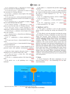
5.1 Boom Components—The basic components of an oil
3.1.29 splash over, n—oil splashing over a boom’s boom are shown in Fig. 1. See Terminology F818 for addi-
freeboard. F818 tional information.
Figure from Lamor Corp., OPRCL1 -11, Oil Containment Boom Types, May 30, 2022.
FIG. 1 Basic Components of an Oil Boom
F3694 − 24
5.2 Boom Types: 5.4.3 The simplified formula can be expressed as:
5.2.1 Curtain booms have a flotation member that com- 1 2
T 5 K × A × V (1)
monly use air, solid foam, or granulated foam with a buoyancy
where:
ratio in the range of 5:1 to 20:1. Curtain booms also have a
flexible, continuous skirt supported by the flotation member. T = tensile force, lb ;
f
1 2 2
K = constant, lb / (ft × knots );
5.2.2 Fence booms have solid flotation members and form
f
A = projected area of the submerged portion of the boom,
the shape of a fence. Fence booms may have centerline or
ft ; and
outboard flotation members Fence booms are very rigid in the
V = tow speed (or current speed), knots.
vertical plane with buoyancy ratio in the range of 3:1 to 6:1.
5.2.3 Specialty booms can include shore-sealing boom and
5.4.4 The values of K were then averaged and simplified
fire boom.
per water body classifications:
5.2.4 Shore-sealing boom is specifically designed to work in
5.4.4.1 Calm water booms under calm conditions, K = 1.7;
the intertidal area to seal the critical area of where the water
5.4.4.2 Protected water booms in regular waves, K = 4.3;
meets the beach. Shore-sealing boom is composed of three
and
tubes. The lower two tubes are filled with water that allows the
5.4.4.3 Open water booms under harbor chop wave
boom to follow the shape of the beach and seal the beach. The 1
conditions, K = 4.7.
top tube is filled with air which gives the boom its flotation as
5.4.5 As the boom is generally towed in “J,” “U,” or “V”
the tide floods.
configurations and anchored at an angle to the boom forces,
5.2.5 Fire boom, or fire-resistant boom is designed and
there will be a reduction in the forces acting on a boom.
constructed to withstand the high temperatures generated
Conditions are dynamic, the boom is towed through wave
during the in-situ burning of oil. There are two basic types of
troughs and crests, and the boom opening (gap) varies. Vessel
fire boom, one type is constructed of a majority of fire-resistant
speeds varying should be accounted for by a substantial margin
materials and the second type is water cooled and using water
of safety in the selection of towing lines, hardware, and power
pumped from the sea and specialized fabric to dissipate the
requirements for towing vessels. A safety factor of three or
heat.
greater should be used.
5.3 Boom Selection—Practice F625/F625M and Guide
5.5 Boom Towing:
F1523 should be consulted in the selection of booms.
5.5.1 The most common types of boom connectors are the
5.4 Forces Generated on a Boom:
Z-connector and slide connectors. Specifications for these
5.4.1 Forces generated on a boom are a combination of
connectors can be found in Guides F962 and F2438. Note that,
forces that are applied by the wind and the current or the
although the Z-connector and slide connectors are different,
towing speed. The force generated by the wind is significantly
they can be joined together. Other type of boom connectors
less than that of the current or towing speed. For winds speeds
includes hinge and pin, hinge and plate, and unicon connectors.
in conditions that allow the use of boom for mechanical
For joining booms with different connectors, Practice F1657/
containment and recovery, the wind effect is not included in
F1657M should be consulted.
these calculations for simplification purposes.
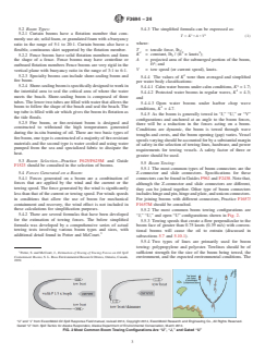
5.5.2 The most common boom towing configurations are
5.4.2 There are several formulas that have been developed
“J,” “U,” and open “U” configurations shown in Fig. 2.
for the estimation of towing forces. The below simplified
5.5.3 Towing speeds that create a flow perpendicular to the
formula was developed by a comprehensive series of actual
boom face of greater than 0.75 knots (0.39 m/s) with conven-
towing tests involving various boom types and sizes, with
tional booms will cause the oil to entrain (discussed in
additional detail found in Potter and McCourt.
subsections 5.7 and 5.10.1).
5.5.4 Two types of lines are primarily used for boom
towing: polypropylene and polyester. Towlines should be of
Potter, S. and McCourt, J., Estimation of Towing of Towing Forces on Oil Spill sufficient strength for the size of the boom being towed, the
Containment Booms, S. L. Ross Environmental Research Ottawa, Ontario, Canada,
environment, and the expected environmental conditions. The
1999.
“U” and “J” from ExxonMobil Oil Spill Response Field manual, revised 2014, Copyright 2014, ExxonMobil Research and Engineering Co., All Rights Reserved.
Gated “U” from Spill Tactics for Alaska Responders, Alaska Department of Environmental Conservation, March 2014.
FIG. 2 Most Common Boom Towing Configurations Are “U”, “J,” and Gated “U”
F3694 − 24
use of nylon towlines is discouraged because of the tendency to 5.6.2.5 Deploy the boom sections; it may be necessary to
recoil (or snapback) during towing operations if the towline stop the deployment of the boom to inflate the air chambers.
breaks (parts).
5.6.2.6 When the boom is deployed, the person in charge
can direct the second towing vessel to pick up the tow line and
5.5.5 For maximum strength, towlines should have eyes
configure the boom.
spliced. If knots are used, the strength of the towline can be
reduced by up to 40 % even if a bowline is used. Towlines can
5.7 Boom Towing Speed:
be susceptible to chafing and damage and, if necessary, chafing
5.7.1 The most essential consideration for a boom’s perfor-
gear of a short-section plastic hose or fire hose should be fitted.
mance for use in containment, exclusion, or deflection is the
Towing lines should be inspected for damage as part of the
boom’s angle and position in relation to the water speed or
preventive maintenance program and additionally before use.
current. Note that, for open water, the speed through the water
5.5.6 To reduce stresses on the boom and the effect of the
is used. Conventional booms cannot contain or exclude oil with
towing vessel propeller wash, longer boom towing lines
water velocities above 0.4 m/s (0.75 knots) because of the
(>50 m) are recommended for open-water booms. Boom tow-
failure of entrainment above this speed. Lower viscosity oils
lines of less than 10 m are not recommended.
escape at lower towing velocities more than viscous oils.
5.5.7 An odd number of boom sections in a boom segment
5.7.2 High-velocity booms using a combination of conven-
should be used so a boom end connector is not located in the
tional boom and netting have shown capability to contain oil up
boom apex in a “U” boom configuration, which may be an area
to 2 m/s (4 knots) before entrainment occurs.
of increased oil leakage potential. When towing the boom, the
5.7.3 For transporting the boom to location after deploy-
apex of the boom should be monitored as any issues with the
ment or repositioning, the resistance caused by the boom
boom, such as entrainment, splash over, or submergence of the
should be reduced to allow for a higher towing speed. This can
boom will appear in the apex area first.
be accomplished by towing the boom with a single tow line in
a straight line by a single vessel, having the two towing vessels
5.6 Boom Towing Vessels:
come together and travel in the same direction, or securing
5.6.1 Towing vessels can be configured in two basic towing
both boom towing lines to a single vessel.
arrangements. The first finds a single-fitting, towing post or
5.7.4 The optimal distance between two towing vessels is
other securing point that is located on the centerline of the
one third of the boom length for a “U” boom configuration.
towing vessel. The towing post should be located as far
When towing the boom, maintain a visual watch on the apex
forward as practical of the towing vessel’s rudder, outboard
(or back) of the boom as indications of problems with the boom
engine, or outdrive to allow for maximum maneuverability.
will show there first and the boom performance is best
The second arrangement is a bridle secured to the towing
determined by visual observation.
vessel’s aft quarter bits with the towline attached to the bridle.
5.6.2 Vessels selected for boom towing require good slow-
5.8 Anchoring the Boom in Coastal Wate
...