

ASTM E3408/E3408M-23
(Test Method)Standard Test Method for Evaluating Ground Response Robot Capabilities: Dexterity: Linear Inspection
General Information
- Abstract
SIGNIFICANCE AND USE
5.1 This test method is part of an overall suite of related test methods that provide repeatable measures of human-system interaction capability including robotic system mobility, dexterity, inspection, remote operator proficiency, and situational awareness. In particular, the operator control unit (OCU) design and interface features may impact the operator’s ability to perform movement and inspection tasks with the robot.
5.2 The test apparatuses are low cost and easy to fabricate so they can be widely replicated. The procedure is also simple to conduct. This eases comparisons across various testing locations, dates, and times to determine best-in-class systems and operators.
5.3 Evaluation—This test method can be used in a controlled environment to measure baseline capabilities. It can also be embedded into operational training scenarios to measure degradation due to uncontrolled variables in lighting, weather, radio communications, GPS accuracy, etc.
5.4 Procurement—This test method can be used to identify inherent capability trade-offs in systems, make informed purchasing decisions, and verify performance during acceptance testing. This aligns requirement specifications and user expectations with existing capability limits.
5.5 Training—This test method can be used to focus operator training, as a repeatable practice task or as an embedded task within training scenarios. The resulting measures of remote operator proficiency enable tracking of perishable skills over time, along with comparisons of performance across squads, regions, or national averages.
5.6 Innovation—This test method can be used to inspire technical innovation, demonstrate break-through capabilities, and measure the reliability of systems performing specific tasks within an overall mission sequence. Combining or sequencing multiple test methods can guide manufacturers toward implementing the combinations of capabilities necessary to perform essential mission tasks.
SCOPE
1.1 This test method is intended for remotely operated ground robots operating in complex, unstructured, and often hazardous environments. It specifies the apparatuses, procedures, and performance metrics necessary to measure the capability of a robot to dexterously inspect objects of interest in the environment at various heights, depths, orientations, and confinement. This test method is one of several related dexterity tests that can be used to evaluate overall system capabilities.
1.2 The robotic system typically includes a remote operator in control of all functionality, so an onboard camera and remote operator display are typically required. Assistive features or autonomous behaviors may improve the effectiveness or efficiency of the overall system.
1.3 Different user communities can set their own thresholds of acceptable performance within this test method for various mission requirements.
1.4 Performing Location—This test method may be performed anywhere the specified apparatuses and environmental conditions can be implemented.
1.5 Units—The International System of Units (SI Units) and U.S. Customary Units (Imperial Units) are used throughout this test method. They are not mathematical conversions. Rather, they are approximate equivalents in each system of units to enable use of readily available materials in different countries. The differences between the stated dimensions in each system of units are insignificant for the purposes of comparing test method results, so each system of units is separately considered standard within this test method.
1.6 This standard does not purport to address all of the safety concerns, if any, associated with its use. It is the responsibility of the user of this standard to establish appropriate safety, health, and environmental practices and determine the applicability of regulatory limitations prior to use.
1.7 This international standard was developed in accordance with inter...
- Status
- Published
- Publication Date
- 14-Sep-2023
- Technical Committee
- E54 - Homeland Security Applications
- Drafting Committee
- E54.09 - Response Robots
Overview
ASTM E3408/E3408M-23: Standard Test Method for Evaluating Ground Response Robot Capabilities: Dexterity: Linear Inspection is an internationally recognized standard published by ASTM International. This test method provides a repeatable, systematic approach for assessing the dexterity and linear inspection capabilities of remotely operated ground robots, particularly those used in complex, unstructured, or hazardous environments. The standard is designed to ensure consistency and comparability in performance evaluations, facilitating procurement, training, and innovation in the robotics field.
Key Topics
- Human-System Interaction: The standard is part of a suite addressing the interaction between human operators and robotic systems, focusing on critical factors such as mobility, dexterity, inspection proficiency, and situational awareness.
- Operator Control Unit (OCU): The design and interface of the operator control unit play a significant role in the operator’s ability to maneuver and carry out inspection tasks.
- Test Apparatus: The required test setups are low-cost and easy to fabricate, enabling widespread adoption and consistent results across various environments and geographic locations.
- Test Environments: Can be conducted in controlled settings or embedded into operational training scenarios to capture real-world variables (e.g., lighting, weather, radio/GPS conditions).
- Performance Metrics: Measures include completeness of inspection, visual acuity achieved, task completion time, and operator proficiency - supporting both baseline assessments and longitudinal skill tracking.
- Customization: Different user communities can set their own performance thresholds to match specific mission requirements, supporting tailored evaluations.
Applications
ASTM E3408/E3408M-23 is valuable across a range of practical scenarios:
- Operational Readiness and Training: Allows organizations to measure and track the proficiency of remote operators and robotic platforms over time, ensuring preparedness for emergency response or hazardous missions.
- Procurement and Acceptance Testing: Offers an objective, standardized way to compare various robotic systems, verify adherence to specification requirements, and support informed purchasing decisions.
- Design Evaluation and Innovation: Enables manufacturers and researchers to assess design trade-offs, integrate new technologies, and demonstrate advanced robotic capabilities under consistent test conditions.
- Mission Planning: Assists emergency response teams and military units in aligning system capabilities with deployment expectations and mission-specific needs.
- Global Consistency: The dual-unit (SI and US Customary) approach ensures the standard’s relevance and usability across international contexts without requiring strict mathematical conversions.
Related Standards
ASTM E3408/E3408M-23 is part of a broader framework developed by ASTM International to address various aspects of robot capabilities. Related standards include:
- ASTM E2521: Terminology for Evaluating Response Robot Capabilities
- ASTM E2566: Test Method for Evaluating Response Robot Sensing: Visual Acuity
- ASTM E2592: Practice for Evaluating Response Robot Capabilities: Logistics: Packaging for Urban Search and Rescue
- ASTM E3349/E3349M: Test Method for Evaluating Ground Robot Capabilities and Remote Operator Proficiency: Terrains: K-Rails
Conclusion
ASTM E3408/E3408M-23 provides a rigorous, practical framework for evaluating the dexterity and linear inspection performance of ground response robots. By establishing clear test procedures and performance metrics, this standard supports enhanced operator training, robust system verification, informed procurement, and ongoing technical innovation. Its global applicability and focus on real-world readiness make it essential for anyone involved in the design, deployment, or use of professional ground robots in challenging environments.
Keywords: ASTM E3408/E3408M-23, ground response robots, dexterity test, linear inspection, remote robot operator, robotic system evaluation, robotic proficiency, robot procurement, operator training standards, performance metrics, international standards for robots, ASTM robotics, robot capability testing.
Frequently Asked Questions
ASTM E3408/E3408M-23 is a standard published by ASTM International. Its full title is "Standard Test Method for Evaluating Ground Response Robot Capabilities: Dexterity: Linear Inspection". This standard covers: SIGNIFICANCE AND USE 5.1 This test method is part of an overall suite of related test methods that provide repeatable measures of human-system interaction capability including robotic system mobility, dexterity, inspection, remote operator proficiency, and situational awareness. In particular, the operator control unit (OCU) design and interface features may impact the operator’s ability to perform movement and inspection tasks with the robot. 5.2 The test apparatuses are low cost and easy to fabricate so they can be widely replicated. The procedure is also simple to conduct. This eases comparisons across various testing locations, dates, and times to determine best-in-class systems and operators. 5.3 Evaluation—This test method can be used in a controlled environment to measure baseline capabilities. It can also be embedded into operational training scenarios to measure degradation due to uncontrolled variables in lighting, weather, radio communications, GPS accuracy, etc. 5.4 Procurement—This test method can be used to identify inherent capability trade-offs in systems, make informed purchasing decisions, and verify performance during acceptance testing. This aligns requirement specifications and user expectations with existing capability limits. 5.5 Training—This test method can be used to focus operator training, as a repeatable practice task or as an embedded task within training scenarios. The resulting measures of remote operator proficiency enable tracking of perishable skills over time, along with comparisons of performance across squads, regions, or national averages. 5.6 Innovation—This test method can be used to inspire technical innovation, demonstrate break-through capabilities, and measure the reliability of systems performing specific tasks within an overall mission sequence. Combining or sequencing multiple test methods can guide manufacturers toward implementing the combinations of capabilities necessary to perform essential mission tasks. SCOPE 1.1 This test method is intended for remotely operated ground robots operating in complex, unstructured, and often hazardous environments. It specifies the apparatuses, procedures, and performance metrics necessary to measure the capability of a robot to dexterously inspect objects of interest in the environment at various heights, depths, orientations, and confinement. This test method is one of several related dexterity tests that can be used to evaluate overall system capabilities. 1.2 The robotic system typically includes a remote operator in control of all functionality, so an onboard camera and remote operator display are typically required. Assistive features or autonomous behaviors may improve the effectiveness or efficiency of the overall system. 1.3 Different user communities can set their own thresholds of acceptable performance within this test method for various mission requirements. 1.4 Performing Location—This test method may be performed anywhere the specified apparatuses and environmental conditions can be implemented. 1.5 Units—The International System of Units (SI Units) and U.S. Customary Units (Imperial Units) are used throughout this test method. They are not mathematical conversions. Rather, they are approximate equivalents in each system of units to enable use of readily available materials in different countries. The differences between the stated dimensions in each system of units are insignificant for the purposes of comparing test method results, so each system of units is separately considered standard within this test method. 1.6 This standard does not purport to address all of the safety concerns, if any, associated with its use. It is the responsibility of the user of this standard to establish appropriate safety, health, and environmental practices and determine the applicability of regulatory limitations prior to use. 1.7 This international standard was developed in accordance with inter...
SIGNIFICANCE AND USE 5.1 This test method is part of an overall suite of related test methods that provide repeatable measures of human-system interaction capability including robotic system mobility, dexterity, inspection, remote operator proficiency, and situational awareness. In particular, the operator control unit (OCU) design and interface features may impact the operator’s ability to perform movement and inspection tasks with the robot. 5.2 The test apparatuses are low cost and easy to fabricate so they can be widely replicated. The procedure is also simple to conduct. This eases comparisons across various testing locations, dates, and times to determine best-in-class systems and operators. 5.3 Evaluation—This test method can be used in a controlled environment to measure baseline capabilities. It can also be embedded into operational training scenarios to measure degradation due to uncontrolled variables in lighting, weather, radio communications, GPS accuracy, etc. 5.4 Procurement—This test method can be used to identify inherent capability trade-offs in systems, make informed purchasing decisions, and verify performance during acceptance testing. This aligns requirement specifications and user expectations with existing capability limits. 5.5 Training—This test method can be used to focus operator training, as a repeatable practice task or as an embedded task within training scenarios. The resulting measures of remote operator proficiency enable tracking of perishable skills over time, along with comparisons of performance across squads, regions, or national averages. 5.6 Innovation—This test method can be used to inspire technical innovation, demonstrate break-through capabilities, and measure the reliability of systems performing specific tasks within an overall mission sequence. Combining or sequencing multiple test methods can guide manufacturers toward implementing the combinations of capabilities necessary to perform essential mission tasks. SCOPE 1.1 This test method is intended for remotely operated ground robots operating in complex, unstructured, and often hazardous environments. It specifies the apparatuses, procedures, and performance metrics necessary to measure the capability of a robot to dexterously inspect objects of interest in the environment at various heights, depths, orientations, and confinement. This test method is one of several related dexterity tests that can be used to evaluate overall system capabilities. 1.2 The robotic system typically includes a remote operator in control of all functionality, so an onboard camera and remote operator display are typically required. Assistive features or autonomous behaviors may improve the effectiveness or efficiency of the overall system. 1.3 Different user communities can set their own thresholds of acceptable performance within this test method for various mission requirements. 1.4 Performing Location—This test method may be performed anywhere the specified apparatuses and environmental conditions can be implemented. 1.5 Units—The International System of Units (SI Units) and U.S. Customary Units (Imperial Units) are used throughout this test method. They are not mathematical conversions. Rather, they are approximate equivalents in each system of units to enable use of readily available materials in different countries. The differences between the stated dimensions in each system of units are insignificant for the purposes of comparing test method results, so each system of units is separately considered standard within this test method. 1.6 This standard does not purport to address all of the safety concerns, if any, associated with its use. It is the responsibility of the user of this standard to establish appropriate safety, health, and environmental practices and determine the applicability of regulatory limitations prior to use. 1.7 This international standard was developed in accordance with inter...
ASTM E3408/E3408M-23 is available in PDF format for immediate download after purchase. The document can be added to your cart and obtained through the secure checkout process. Digital delivery ensures instant access to the complete standard document.
Standards Content (Sample)
This international standard was developed in accordance with internationally recognized principles on standardization established in the Decision on Principles for the
Development of International Standards, Guides and Recommendations issued by the World Trade Organization Technical Barriers to Trade (TBT) Committee.
Designation: E3408/E3408M − 23
Standard Test Method for
Evaluating Ground Response Robot Capabilities: Dexterity:
Linear Inspection
This standard is issued under the fixed designation E3408/E3408M; the number immediately following the designation indicates the year
of original adoption or, in the case of revision, the year of last revision. A number in parentheses indicates the year of last reapproval.
A superscript epsilon (´) indicates an editorial change since the last revision or reapproval.
INTRODUCTION
The robotics community needs ways to measure whether a particular robot is capable of performing
specific missions in complex, unstructured, and often hazardous environments. These missions require
various combinations of elemental robot capabilities. Each capability can be represented as a test
method with an associated apparatus to provide tangible challenges for various mission requirements
and performance metrics to communicate results. These test methods can then be combined and
sequenced to evaluate essential robot capabilities and remote operator proficiencies necessary to
successfully perform intended missions.
The ASTM International Standards Committee on Homeland Security Applications (E54) specifies
these standard test methods to facilitate comparisons across different testing locations and dates for
diverse robot sizes and configurations. These standards support robot researchers, manufacturers, and
user organizations in different ways. Researchers use the standards to understand mission
requirements, encourage innovation, and demonstrate break-through capabilities. Manufacturers use
the standards to evaluate design decisions, integrate emerging technologies, and harden systems.
Emergency responders and soldiers use them to guide purchasing decisions, align deployment
expectations, and focus training with standard measures of operator proficiency. Associated usage
guides describe how these standards can be applied to support various objectives.
Several suites of standards address these elemental capabilities including maneuvering, mobility,
dexterity, sensing, energy, communications, durability, proficiency, autonomy, and logistics. This
standard is part of the dexterity suite of test methods.
1. Scope 1.3 Different user communities can set their own thresholds
of acceptable performance within this test method for various
1.1 This test method is intended for remotely operated
mission requirements.
ground robots operating in complex, unstructured, and often
hazardous environments. It specifies the apparatuses, 1.4 Performing Location—This test method may be per-
procedures, and performance metrics necessary to measure the formed anywhere the specified apparatuses and environmental
capability of a robot to dexterously inspect objects of interest conditions can be implemented.
in the environment at various heights, depths, orientations, and
1.5 Units—The International System of Units (SI Units) and
confinement. This test method is one of several related dexter-
U.S. Customary Units (Imperial Units) are used throughout this
ity tests that can be used to evaluate overall system capabilities.
test method. They are not mathematical conversions. Rather,
1.2 The robotic system typically includes a remote operator they are approximate equivalents in each system of units to
in control of all functionality, so an onboard camera and remote
enable use of readily available materials in different countries.
operator display are typically required. Assistive features or The differences between the stated dimensions in each system
autonomous behaviors may improve the effectiveness or effi-
of units are insignificant for the purposes of comparing test
ciency of the overall system. method results, so each system of units is separately considered
standard within this test method.
1.6 This standard does not purport to address all of the
This test method is under the jurisdiction of ASTM Committee E54 on
safety concerns, if any, associated with its use. It is the
Homeland Security Applications and is the direct responsibility of Subcommittee
responsibility of the user of this standard to establish appro-
E54.09 on Response Robots.
priate safety, health, and environmental practices and deter-
Current edition approved Sept. 15, 2023. Published October 2023. DOI:
10.1520/E3408_E3408M-23. mine the applicability of regulatory limitations prior to use.
Copyright © ASTM International, 100 Barr Harbor Drive, PO Box C700, West Conshohocken, PA 19428-2959. United States
E3408/E3408M − 23
1.7 This international standard was developed in accor-
dance with internationally recognized principles on standard-
ization established in the Decision on Principles for the
Development of International Standards, Guides and Recom-
mendations issued by the World Trade Organization Technical
Barriers to Trade (TBT) Committee.
2. Referenced Documents
2.1 ASTM Standards:
E2521 Terminology for Evaluating Response Robot Capa-
bilities
E2566 Test Method for Evaluating Response Robot Sensing:
Visual Acuity
E2592 Practice for Evaluating Response Robot Capabilities:
Logistics: Packaging for Urban Search and Rescue Task
Force Equipment Caches
E3349/E3349M Test Method for Evaluating Ground Robot
Capabilities and Remote Operator Proficiency: Terrains:
K-Rails
3. Terminology
3.1 Definitions—The following terms are used in this test
method and are defined in Terminology E2521: abstain,
administrator or test administrator, emergency response robot
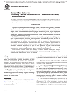
FIG. 1 Alcove Apparatus with a Linear Rail Mounted on the
or response robot, fault condition, operator, operator station,
Outside Wall and a Linear Rail
remote control, repetition, robot, stepfield terrain element,
Mounted on Top of a Platform Inside of the Alcove
teleoperation, test event or event, test form, test sponsor, test
suite, testing target or target, testing task or task, and trial or
test trial.
3.2.3 diagonal rail, n—a solid piece of dimensional lumber
3.2 Definitions of Terms Specific to This Standard:
that is sized to fit horizontally inside a subfloor at a 45° angle
3.2.1 alcove, n—a square area with walls on three of four to the direction of travel.
sides whose sides are equal to the chosen apparatus clearance
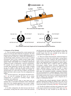
3.2.4 Landolt Ring or Landolt C, n—an optotype, or
width (W); see Fig. 1.
symbol, consisting of a black circular ring with a white gap or
vice versa, both with specified sizes, as defined in Test Method
3.2.2 apparatus clearance width (W), n—a specification for
E2566.
the apparatus dimensions chosen from one of four possible
measurements, based on the intended robot deployment envi-
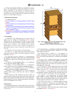
3.2.5 linear rail, n—a length of wood, plastic, or metal with
ronment:
four mounting points used to hold additional hardware to
(1) 240 cm 6 2.5 cm tolerance [96 in. 6 1 in. tolerance],
perform dexterity tasks; the two outermost points are each
such as open and outdoor public spaces;
positioned normal to the rail and the two innermost points are
(2) 120 cm 6 2.5 cm tolerance [48 in. 6 1 in. tolerance],
each angled 45° to the rail.
such as indoor spaces in accessibility-compliant buildings;
3.2.5.1 Discussion—In this standard, the linear rail contains
(3) 60 cm 6 1.3 cm tolerance [24 in. 6 0.5 in. tolerance],
inspect tasks that consist of PVC pipes and visual acuity
residences and aisles of public transportation; or
targets, as shown in Fig. 2. See Section 6 for more information.
(4) 30 cm 6 1.3 cm tolerance [12 in. 6 0.5 in. tolerance],
3.2.6 platform, n—a flat square panel, whose sides measure
cluttered indoor spaces, ductwork, and voids in collapsed
one apparatus clearance width (W), that can hold a linear rail.
structures.
3.2.6.1 Discussion—See Section 6 for more information.
3.2.2.1 Discussion—The measures for these scales are
3.2.7 subfloor, n—an underlayment of Oriented Strand
nominal and do not represent the measurement of the narrowest
Board (OSB) or similar material with dimensional lumber
point in the apparatus through which the robot should pass.
borders used to affix multiple subfloors to one another and can
Consult Section 6 for the overall measurements and dimen-
contain apparatus elements such as terrains or obstacles.
sions of the apparatus at each scale.
3.2.8 visual acuity target, n—a printed graphic of nested
Landolt C symbols of varying sizes and orientations. The
orientation of each C is defined by the direction of the gap in
For referenced ASTM standards, visit the ASTM website, www.astm.org, or
the ring out from the center.
contact ASTM Customer Service at service@astm.org. For Annual Book of ASTM
3.2.8.1 Discussion—This is the same type of artifact used in
Standards volume information, refer to the standard’s Document Summary page on
the ASTM website. Test Method E2566 – 17a. See Fig. 3.
E3408/E3408M − 23
FIG. 2 Linear Rail with Inspect Tasks
FIG. 3 Example Visual Acuity Targets and the Corresponding Ring Gap Orientations
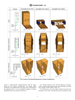
4. Summary of Test Method onto the terrain; the test begins once the full body of the robot
is contained on the terrain. The robot attempts to inspect all
4.1 This test method is performed by a remote operator who
possible targets from the four available on the linear rail
cannot see or hear the robot within the test apparatus. The robot
positioned in the apparatus. See Fig. 4.
traverses over a defined area of terrain and performs tasks on
a linear rail. For a given test, a linear rail is positioned at a
4.3 This test evaluates linear dexterity, wherein all targets to
specified height, depth, orientation, and in an open or confined
be inspected are on linear rails which require varying degrees
environment. Each of these variables (terrain, height, depth,
of freedom in order to be completed. The position (height or
orientation, and confinement) are to be selected by the test
depth, or both), orientation (viewable from the front, below, or
sponsor, likely with multiple tests of different combinations
above), and confinement (open, rectangular, or square confine-
conducted in order to demonstrate a spread of performance.
ment) of the linear rails is varied in order to represent
For example, the test sponsor may specify conditions that
increasingly complex robotic dexterity capabilities (for
resemble target deployment scenarios (for example, reaching
example, longer manipulators in order to reach high or deep set
on top of a shelf) or allow for the robot vendor to select
targets, additional degrees of freedom in order to inspect
minimum, maximum, and median settings (for example, in-
targets at varying orientations using the robot’s camera, con-
specting targets on a wall at the lowest, highest, and mid-point
fined space for constrained dexterity evaluation). Dexterity
heights that robot is able to reach). Two test configurations are
tests can be performed in a standard apparatus (which features
defined:
diagonal rail terrain) or as part of an embedded scenario (using
4.1.1 Standard Apparatus—The apparatus described in Sec-
the available terrain of the scenario or standard terrain elements
tion 6 are used for mounting the linear rail in various
that are added to the environment, such as diagonal rails or
configurations of parameters including height, depth,
ramps, or combinations thereof).
orientation, and confinement.
4.4 Based on the selected apparatus clearance width (W),
4.1.2 Embedded Scenario—One or more linear rails are
apparatus dimensional settings are defined such as the size of
mounted into a real-world environment whose dimensions
the alcove, the dimensions of the linear rails, and the size of the
mimic that of the standard apparatus in one or more configu-
visual acuity targets; see Section 6 and Table 1 for more details.
rations of parameters for height, depth, orientation, and con-
finement.
4.5 For this test method, each linear rail contains four visual
4.2 In either configuration, the robot traverses into the test acuity targets mounted recessed inside of PVC pipes (see Fig.
environment, crossing from the A-side to the B-side and then 2) such that they are only viewable by the robot when its
E3408/E3408M − 23
FIG. 4 Layout of the Standard Apparatuses in Various Configurations
camera is approximately aligned/centered with the target. 4.5.1 Height—Based on the selected apparatus clearance
Based on test sponsor specifications, the height, depth, width, starting from 0/ground level and increasing by 0.25W
orientation, and confinement of the linear rail is positioned in (for example, 0.25W, 0.5W, 0.75W, etc.).
the apparatus from a set of predefined settings as follows 4.5.2 Orientation—Set to be either viewable from the front
(additional detail is provided in Section 6): (mounted on the wall), viewable from above (mounted on top
E3408/E3408M − 23
TABLE 1 All Possible Combinations of Test Settings
4.8 Two sizes of visual acuity targets (V) are available,
identified by the diameter of the outer edge of the black ring
NOTE 1—“Etc.” implies that the values continue increasing as high or
(inside of the colored ring): 4 cm [1.5 in.] and 2.1 cm [0.8 in.].
deep as needed based on test sponsor specifications.
Target size is determined based on the selected apparatus
Orientation Height Range Confinement Depth Range
clearance width (W); more information is provided in Section
Viewable from the 0/ground level, Open,
front 0.25W, 0.5W, rectangular, or 0
6. The corresponding levels of acuity for the available Landolt
0.75W, 1W, etc. square
C symbols for each target size are shown in Table 2. The
Landolt C symbols are labeled C1 (largest) through C5
Viewable from 0/ground level, Open,
0, 0.25W, 0.5W,
above 0.25W, 0.5W, rectangular, or
(smallest); note that the corresponding acuity for some Landolt
0.75W, etc.
0.75W, 1W, etc. square
C symbols (that is, the size of the opening in the C) are marked
as “N/A” due to limitations in printing the targets, which
Viewable from 0.25W, 0.5W, Open,
0, 0.25W, 0.5W,
below 0.75W, 1W, rectangular, or
prevents some of the smallest Landolt Cs from being printed
0.75W, etc.
1.25W, etc. square
legibly. The orientations observed by the operator shall be
compared to an answer key after the test is complete in order
to determine the level of acuity achieved.
of a shelf), or viewable from below (mounted underneath a
4.9 Outside of the alcove is terrain where the robot is
shelf; only applicable when confined).
positioned while performing the dexterity task. For the stan-
4.5.3 Depth—Based on the selected apparatus clearance
dard apparatus, the K-Rails terrain (specified in Test Method
width, starting from 0 and increasing by 0.25W (for example,
E3349/E3349M) is used (see Fig. 6). For the embedded
0.25W, 0.5W, 0.75W, etc.).
scenario, the terrain that already exists in the environment can
4.5.4 Confinement—The artifact is mounted in open space
be used (for example, carpet, concrete).
or in confined space (rectangular or square confinement).
4.10 Metrics are recorded for each test conducted and across
4.6 See Fig. 4 for examples of each type of dexterity test.
a set of tests (see Section 9 for more information):
Some combinations of test settings are not possible due to
4.10.1 Per Test—For each test, metrics recorded include (in
dimensional limitations of the apparatus and real-world appli-
order of priority): completeness (number of visual acuity
cability (for example, an artifact oriented to be viewable from
targets inspected), acuity (visual acuity level achieved per
below cannot be mounted at ground level); see Table 1 for all
inspected target and average across all targets), and time (time
possible combinations of test settings.
to complete the test). The heights, depths, orientations (view-
4.7 To inspect the visual acuity targets, the operator shall able from the front, above, or below), and confinement (open
or confined) of the linear rails, as well as the terrain, shall also
use the robot’s camera to identify the targets that are viewable
by the robot’s camera, moving the robot and manipulator(s) as be recorded in the test report along with the metrics.
necessary. Some targets may not be able to be inspected due to 4.10.2 Across Tests—Additional metrics are reported across
limitations in the robot’s capability such as its camera a set of tests. These metrics are only applicable to tests that
resolution, reach of its inspection camera, or its manipulator evaluate dexterity at the same orientation (viewable from the
degrees of freedom. To successfully inspect a visual acuity front, above, or below), in the same type of confinement (open
target, the operator must first be able to see the entire black or or confined), and the same terrain, but with variable heights
white ring inside of the colored ring (outside of the Landolt Cs) and depths. For example, two tests using standard apparatus
test configurations with linear rails oriented to be viewable
on the OCU display of the robot’s camera (see Fig. 5 for
examples of correct and incorrect alignment). The operator from the front, in rectangular confinement, set at two different
then must correctly discern the orientation of the gap in the heights for the lowest and highest position achievable. Across
Landolt Cs relative to the top of the target (marked by a a set of tests, metrics recorded include: minimum height,
number/letter), for example, top, top-right, bottom, etc., doing maximum height, height range, minimum depth, maximum
so down to the smallest Landolt C that they are able to. depth, depth range, and acuity (average across all targets from
NOTE 1—Correct alignment is defined as when the operator is able to see the entire black or white outer ring outside of the Landolt Cs (inside of the
colored ring), as shown in the left and middle image.
FIG. 5 Examples of Correct and Incorrect Alignment
E3408/E3408M − 23
TABLE 2 Levels of Acuity Achievable for Each Target Size
(OCU) design and interface features may impact the operator’s
ability to perform movement and inspection tasks with the
NOTE 1—N/A indicates Landolt Cs that cannot be printed legibly,
robot.
meaning they cannot be inspected.
Visual acuity target size (V)
5.2 The test apparatuses are low cost and easy to fabricate
Landolt C 4 cm [1.5 in.] 2.1 cm [0.8 in.]
so they can be widely replicated. The procedure is also simple
C1 5.0 mm [0.2 in.] 2.6 mm [0.1 in.]
to conduct. This eases comparisons across various testing
C2 2.0 mm [0.08 in.] 1.0 mm [0.04 in.]
locations, dates, and times to determine best-in-class systems
C3 0.8 mm [0.03 in.] 0.4 mm [0.02 in.]
and operators.
C4 0.3 mm [0.01 in.] N/A
C5 N/A N/A
5.3 Evaluation—This test method can be used in a con-
trolled environment to measure baseline capabilities. It can
also be embedded into operational training scenarios to mea-
sure degradation due to uncontrolled variables in lighting,
all tests). Only a subset of these metrics may be applicable
weather, radio communications, GPS accuracy, etc.
depending on the tests that are run. For example, any depth
metrics are only applicable to tests that use the viewable from 5.4 Procurement—This test method can be used to identify
above or below orientations.
inherent capability trade-offs in systems, make informed pur-
chasing decisions, and verify performance during acceptance
4.11 Test completion is defined as when the operator deter-
testing. This aligns requirement specifications and user expec-
mines that they have attempted to inspect all targets possible
tations with existing capability limits.
(for example, if the robot is not able to physically reach a high
target, then it may not be possible to inspect that target) and
5.5 Training—This test method can be used to focus opera-
announces this to the test administrator. The test may also end
tor training, as a repeatable practice task or as an embedded
prematurely if the maximum test time (set by the test sponsor)
task within training scenarios. The resulting measures of
is exceeded. Setting a maximum test time as criteria for a
remote operator proficiency enable tracking of perishable skills
successful test is optional.
over time, along with comparisons of performance across
squads, regions, or national averages.
4.12 Potential faults include:
4.12.1 Any contact by the robot with the apparatus that
5.6 Innovation—This test method can be used to inspire
requires adjustment or repair to return the apparatus to the
technical innovation, demonstrate break-through capabilities,
initial condition. If a linear rail or the visual acuity targets, or
and measure the reliability of systems performing specific tasks
both, are moved or damaged significantly by the robot during
within an overall mission sequence. Combining or sequencing
testing, the operator will be instructed to pause robot operation
multiple test methods can guide manufacturers toward imple-
while the test administrator repairs the apparatus and notes the
menting the combinations of capabilities necessary to perform
fault on the report form. The test timer will continue to count
essential mission tasks.
time while the repair is made. If part of the apparatus (for
example, walls, terrain) is moved or damaged significantly by
6. Apparatus
the robot during testing, the operator will be instructed to pause
6.1 This section specifies the apparatuses used in both the
robot operation while the test administrator repairs the appa-
standard apparatus and embedded scenario configurations. For
ratus and notes the fault on the report form. The test timer will
both configurations, the dimensional characteristics specified
be paused until the repairs have been made. If necessary, the
for the linear rails and visual acuity targets shall be followed.
robot shall be extracted from the test apparatus in order for the
For the standard apparatus, all other dimensional characteris-
repair to be made, and then returned to the position where the
tics specified in this section shall be used when fabricating the
fault occurred to continue testing.
apparatuses in order to run the test. For the embedded scenario,
4.12.2 Any visual, audible, or physical interaction that
all other dimensional characteristics (except for the terrain)
assists either the robot or the remote operator. For example, if
shall be used to characterize the real-world environment used,
the robot has a failure that would require it to be manually reset
with some variance allowed.
(for example, if the robot’s tracks fall off, then the operator
6.2 The standard apparatus consists of diagonal rails set
would have to enter the test apparatus to repair them), this
into subfloors to form the terrain, an alcove, a platform,
would constitute a fault. However, if the robot has a failure that
confinement walls, and a linear rail. The alcove and confine-
can be repaired while the operator remains remote (for
ment walls are only required if dexterity in confinement is
example, if the robot’s software has to be reset and this can be
being evaluated. If dexterity in the open configuration is being
performed without the operator entering the test apparatus),
evaluated, then only a wall panel is needed; however, the
this would not constitute a fault.
outside wall of an alcove can be used if desired.
5. Significance and Use
6.3 The main apparatus dimension to consider is the appa-
5.1 This test method is part of an overall suite of related test ratus clearance width (W) for the robot, which can be set to
methods that provide repeatable measures of human-system 120 cm 6 2.5 cm tolerance [48 in. 6 1 in. tolerance], 60 cm 6
interaction capability including robotic system mobility, 1.3 cm tolerance [24 in. 6 0.5 in. tolerance], or 30 cm 6
dexterity, inspection, remote operator proficiency, and situ- 1.3 cm tolerance [12 in. 6 0.5 in. tolerance]. The dimension
ational awareness. In particular, the operator control unit chosen for W should represent the intended deployment
E3408/E3408M − 23
NOTE 1—The K-Rails terrain used in the standard apparatus configurations shown with the linear rails oriented to be viewable from the front. The
terrain is positioned outside of the alcove adjacent to the wall in the open configuration (left), outside of the alcove adjacent to the wall with two additional
walls in the rectangular confinement condition (middle), and adjacent to the alcove with three additional walls in the square confinement configuration
(right).
FIG. 6 K-Rails Terrain Used in the Standard Apparatus
environment or be based on the size of the robot (that is, the each apparatus clearance width (W). See Figs. 7-11 for
robot shall be able to maneuver within the selected dimensions dimensional diagrams of the apparatus.
of the apparatus), or both. All apparatus dimensions scale
6.4 Visual Acuity Targets—Visual acuity targets are
proportionally with 1W; the width of the terrain is 1W, the
mounted at the bottom of the PVC pipes. The dimensions of the
length of the terrain is 2W, the position of the linear rails is
PVC pipes (T and L) and visual acuity targets (V) change
selected from a set of predefined heights and depths based on
based on the value of W (see Table 3). The visual acuity targets
W (starting from 0/ground level and increasing by 0.25W; for
consist of Landolt C symbols, which are used as described in
example, 0.25W, 0.5W, 0.75W, etc.), the area of the alcove and
Test Method E2566 (see Fig. 12). Each symbol consists of a
the platform are both 1W by 1W, and the position of the targets
ring with an outer diameter equal to five times the ring
on the linear rails are based on W (the two outer targets normal
thickness displayed on a background of inverted color com-
to the rail are each 0.25W distance from the center of the rail
pared to the ring, to maximize contrast. The ring contains a gap
and the two inner targets angled 45° to the rail are each 0.67W
with parallel edges equal to the ring thickness. The size of the
distance from the center of the rail). The diagonal rail height
gap represents the smallest discernible feature when measuring
(H) for the terrain, the size of the visual acuity targets (V), and
the length (L) and width (T) of the pipes used on the linear rails visual acuity and is reported as the metric. The gap appears in
also scales with W. See Table 3 for all apparatus dimensions at one of eight radial orientations around the ring at 45° intervals.
TABLE 3 Apparatus Dimensions Based on Apparatus Clearance Width
Linear Rail Linear Rail
Apparatus Height/ Outer Inner Visual Target
Intended Terrain Terrain Diagonal Target
Clearance Depth Alcove Area Target Target Acuity Pipes
Deployment Width Length Rail Height Pipes Width
Width Increments (1W by 1W) Distance Distance Targets Length
Environment (1W) (2W) (H) (T)
(W) (0.25W) from Center from Center (V) (L)
(0.25W) (0.67W)
Open: Rooms 120 cm 120 cm 240 cm 30 cm 120 cm by 30 cm 20 cm 10 cm 4 cm 10 cm 5 cm
Confined: Hallways, [48 in.] [48 in.] [96 in.] [12 in.] 120 cm [12 in.] [8 in.] [4 in.] [1.5 in.] [4 in.] [2 in.]
bathrooms, and [48 in. by
closets 48 in.]
Open: Public 60 cm 60 cm 120 cm 15 cm 60 cm by 15 cm 10 cm 5 cm 2.1 cm 5 cm 2.5 cm
transportation [24 in.] [24 in.] [48 in.] [6 in.] 60 cm [6 in.] [4 in.] [2 in.] [0.8 in.] [2 in.] [1 in.]
Confined: Cluttered [24 in. by
interiors 24 in.]
Open: Constrained 30 cm 30 cm 60 cm 7.5 cm 30 cm by 7.5 cm 5 cm 2.5 cm 2.1 cm 2.5 cm 2.5 cm
spaces [12 in.] [12 in.] [24 in.] [3 in.] 30 cm [3 in.] [2 in.] [1 in.] [0.8 in.] [1 in.] [1 in.]
Confined: Voids in [12 in. by
collapsed structures 12 in.]
E3408/E3408M − 23
FIG. 7 Standard Apparatus Shown at Each Apparatus Clearance Width (W) in Various Example Configurations
FIG. 8 Dimensional Layout of the Pipes and Visual Acuity Targets on the Linear Rail
FIG. 9 Height Settings Outside of the Alcove in the Open Configuration for Linear Rails Oriented to be Viewable from the Front
Identifying gap orientations of Landolt C symbols with gaps of in this test method can be downloaded. Note that all targets
a particular size is related to the ability to resolve visual must be printed at actual size and shall not be scaled;
identification of objects of that size. Five Landolt C symbols otherwise, the associated acuity measures for each target will
are arranged in a concentric manner, with the largest 50 % of be impacted. The report form provided in Section 10 includes
the diameter of the overall target and each successive symbol an answer key to use when comparing the orientations the
is 40 % of the diameter of the previous. The smallest optotype operator discerns during test performance.
that can be resolved with the desired level of statistical
significance represents the measured visual acuity of the
Link:
system in the context of this test. The visual acuity targets used https://drive.google.com/file/d/1sUsX4rlm24LqcEe3ARNsXyBYfgyDjw0z/edit.
E3408/E3408M − 23
FIG. 10 Platform Height Settings for Linear Rails Oriented to be Viewable from Above in t
...