

EN 1995-3:2025/prA1
(Amendment)Eurocode 5 - Design of timber structures - Part 3: Execution
- Abstract
1.1 Scope of EN 1995-3
(1) This document gives minimum requirements for execution of timber structures (buildings and bridges) designed in accordance with EN 1995 (all parts) to ensure that what is built meets the requirements for mechanical resistance, serviceability, durability, and fire performance.
(2) This document gives guidance on moisture control during transport to the building site, storage on site, handling on site and erection.
(3) This document gives guidance on workmanship and deviation limits during execution.
(4) This document assumes that there is an execution specification which states all the specific requirements relevant for the execution of a particular structure.
(5) For products covered by a European technical product specification, this document only covers those aspects of fabrication such as cutting, machining and drilling after placement of the product on the market.
(6) This document does not cover:
a) parts which are not designed according to EN 1995;
b) temporary works (such as formwork, scaffolding, propping, shoring, etc.);
c) specification, production and conformity of timber members in accordance with European technical product specifications;
d) deviation limits for other properties than mechanical resistance, serviceability, durability and fire performance;
e) contractual aspects, responsibilities of the various parties, competency requirements or the degree of independence of the personnel undertaking the inspection;
f) health and safety requirements during execution.
1.2 Assumptions
(1) It is assumed that all relevant provisions of EN 1995 are complied with.
(2) It is recognized in this document that areas such as detailed requirements for competence of personnel, and details related to Quality Management are within the competence of the CEN Member States.
(3) Before the execution begins on a part of the structure, it is assumed that the following are available on site:
— the drawings and specification of that part;
— the execution specification.
(4) Before the start of the execution, it is assumed that the execution specification has been checked for completeness.
(5) It is assumed that previous work (such as foundations) has been inspected and that any work which needs to be done due to deviations from the execution specification has been carried out.
- Status
- Not Published
- Publication Date
- 19-Jan-2028
- Technical Committee
- CEN/TC 250 - Structural Eurocodes
- Drafting Committee
- CEN/TC 250/SC 5/WG 9 - Execution
- Current Stage
- 4020 - Submission to enquiry - Enquiry
- Start Date
- 10-Sep-2026
- Due Date
- 08-Oct-2026
- Completion Date
- 10-Sep-2026

EN 1995-3:2025/prA1 is a CEN draft amendment to EN 1995-3:2025, Eurocode 5 - Design of timber structures - Part 3: Execution. It updates the execution rules for timber structures in buildings and bridges so the work on site matches the design intent for mechanical resistance, serviceability, durability and fire performance. It is written for designers, contractors, inspectors and quality staff who need the execution requirements to be clear and measurable.
What does EN 1995-3:2025/prA1 specify?
EN 1995-3:2025/prA1 amends the execution standard for timber structures designed to EN 1995. The base document sets minimum requirements for execution, plus guidance on moisture control, workmanship and deviation limits, and it assumes that a project-specific execution specification is available.
The draft amendment is organized as modifications to the Introduction, Clause 3, Clause 4, Clause 5, Clause 6, Annexes A, B, C, D and F, and the Bibliography.
| Annex | What it covers |
|---|---|
| Annex A | Inspection levels, sample size, acceptance criteria and documentation of quality control |
| Annex B | Bonding, including adhesive fillings, surface preparation, pressing and screw-press bonding |
| Annex C | Timber foundation piles |
| Annex D | Carpentry joints - deviation limits |
| Annex F | Expanded tube connections and DLW reinforcement |
What are the key requirements of EN 1995-3:2025/prA1?
Clause 4 makes the execution specification central. EN 1995-3:2025/prA1 assumes the drawings and execution specification are on site before work starts on each part of the structure, and that the specification has been checked for completeness. In practice, this means the project team must close out missing details before erection begins, not after.
Clause 4 and Clause 5 place emphasis on planning the work sequence. The execution documentation must address the erection sequence and any temporary support or bracing needed for stability as work proceeds. That matters because timber structures can behave differently during erection than they do in the finished condition.
Clause 5 also strengthens the workmanship requirements. The provisions of the standard, the manufacturer’s instructions and the execution specification shall be applied, and moisture control is highlighted for transport, storage, handling and erection. The draft amendment also adds a note on reducing wetting risks to limit problems such as swelling and hydrogen embrittlement in fasteners.
Clause 6 gives the practical control limits for geometry. It requires the measuring device to be recorded and provides deviation tables for cut and machined geometry, holes, notches, fastener spacings, edge and end distances, panel connections and fastener position. For the reader, this is the part used to decide whether a fabricated or erected member is within acceptable tolerance.
Annex A covers inspection levels, sample size, acceptance criteria and quality-control records. That gives the project team a sampling and acceptance framework for checking production and site work.
Annex B is the detailed bonding section. It covers structural bonding and adhesive fillings, surface quality, training, pressing, equilibrium moisture content groups, screw-press bonding and corrective action. For execution, this is where the bonding process has to be planned and documented, not just carried out.
Annexes C, D and F address special cases: timber foundation piles, carpentry joints and expanded tube connections. Annex F also adds a requirement to keep DLW dry or protected against direct water take up during execution and erection.
What terms does EN 1995-3:2025/prA1 define?
- Execution specification - the project document that states the specific requirements for execution of a particular structure.
- Quality control - the inspection, sampling, acceptance and documentation process used to verify execution quality.
- Geometrical deviations - the permitted differences between intended and actual dimensions, positions and clearances.
- Bonding - joining timber products with adhesive, including adhesive fillings and screw-press bonding.
- Densified laminated wood (DLW) - the material named in Annex F that must be kept dry or protected from direct water uptake.
- Gypsum based (GYP) - one of the material abbreviations used in the fastener-position tables.
- Wood-particle-based (WPB) - one of the panel abbreviations used in the bonding and fastener provisions.
Who uses EN 1995-3:2025/prA1?
EN 1995-3:2025/prA1 is used by structural engineers, timber contractors, fabricators, site supervisors, inspectors and quality managers working on timber buildings and bridges. It is also relevant to buyers and project managers who need to check what has to be documented, inspected, measured and accepted before the structure is handed over.
What changed in EN 1995-3:2025/prA1 from the previous edition?
EN 1995-3:2025/prA1 amends EN 1995-3:2025. The draft updates the reference to EN 1990-1, adds new abbreviations in Clause 3, and revises Clause 4 on documentation, Clause 5 on workmanship and Clause 6 on geometrical deviations.
It also revises Annex A on quality-control inspection, Annex B on bonding and adhesive fillings, Annex C on timber foundation piles, Annex D on carpentry joints and Annex F on expanded tube connections. The Bibliography is updated to match the revised references used in the text.
Which standards are used with EN 1995-3:2025/prA1?
- EN 1990-1:2023+A1:2026 - the basis of structural and geotechnical design used in the updated references.
- EN 1995 (all parts) - the design basis for the timber structures whose execution is covered here.
- EN 1995-1-1:2025 - supplies resistance and parameter values cited in Annex B and Annex C.
- EN 1995-1-3 - named in the updated Introduction for timber-concrete composite structures.
- EN 17418 - provides the adhesive used for adhesive fillings in Annex B.
What does the EN 1995-3:2025/prA1 document contain?
The draft amendment updates tables, figures, formulas and notes across the document. Clause 6 contains the main deviation tables for machined members, fasteners, panel connections and fastener head position, while Annex B includes updated figures, a moisture-content grouping table, a table for minimum penetration of screw heads, and a formula-based check for screw-press bonding pressure.
It also revises the wording of documentation and workmanship provisions, including erection sequence, temporary support and corrective measures. Annex F adds updated figure keys for DLW reinforcement and a new execution note on keeping DLW dry.
Relations
- Effective Date
- 19-Nov-2025
Get Certified
Connect with accredited certification bodies for this standard

DIBt (Deutsches Institut für Bautechnik)
German Institute for Building Technology.
DIN CERTCO
DIN Group product certification.

Aboma Certification B.V.
Specialized in construction, metal, and transport sectors.
Sponsored listings
Frequently Asked Questions
EN 1995-3:2025/prA1 is a draft published by the European Committee for Standardization (CEN). Its full title is "Eurocode 5 - Design of timber structures - Part 3: Execution". This standard covers: 1.1 Scope of EN 1995-3 (1) This document gives minimum requirements for execution of timber structures (buildings and bridges) designed in accordance with EN 1995 (all parts) to ensure that what is built meets the requirements for mechanical resistance, serviceability, durability, and fire performance. (2) This document gives guidance on moisture control during transport to the building site, storage on site, handling on site and erection. (3) This document gives guidance on workmanship and deviation limits during execution. (4) This document assumes that there is an execution specification which states all the specific requirements relevant for the execution of a particular structure. (5) For products covered by a European technical product specification, this document only covers those aspects of fabrication such as cutting, machining and drilling after placement of the product on the market. (6) This document does not cover: a) parts which are not designed according to EN 1995; b) temporary works (such as formwork, scaffolding, propping, shoring, etc.); c) specification, production and conformity of timber members in accordance with European technical product specifications; d) deviation limits for other properties than mechanical resistance, serviceability, durability and fire performance; e) contractual aspects, responsibilities of the various parties, competency requirements or the degree of independence of the personnel undertaking the inspection; f) health and safety requirements during execution. 1.2 Assumptions (1) It is assumed that all relevant provisions of EN 1995 are complied with. (2) It is recognized in this document that areas such as detailed requirements for competence of personnel, and details related to Quality Management are within the competence of the CEN Member States. (3) Before the execution begins on a part of the structure, it is assumed that the following are available on site: — the drawings and specification of that part; — the execution specification. (4) Before the start of the execution, it is assumed that the execution specification has been checked for completeness. (5) It is assumed that previous work (such as foundations) has been inspected and that any work which needs to be done due to deviations from the execution specification has been carried out.
1.1 Scope of EN 1995-3 (1) This document gives minimum requirements for execution of timber structures (buildings and bridges) designed in accordance with EN 1995 (all parts) to ensure that what is built meets the requirements for mechanical resistance, serviceability, durability, and fire performance. (2) This document gives guidance on moisture control during transport to the building site, storage on site, handling on site and erection. (3) This document gives guidance on workmanship and deviation limits during execution. (4) This document assumes that there is an execution specification which states all the specific requirements relevant for the execution of a particular structure. (5) For products covered by a European technical product specification, this document only covers those aspects of fabrication such as cutting, machining and drilling after placement of the product on the market. (6) This document does not cover: a) parts which are not designed according to EN 1995; b) temporary works (such as formwork, scaffolding, propping, shoring, etc.); c) specification, production and conformity of timber members in accordance with European technical product specifications; d) deviation limits for other properties than mechanical resistance, serviceability, durability and fire performance; e) contractual aspects, responsibilities of the various parties, competency requirements or the degree of independence of the personnel undertaking the inspection; f) health and safety requirements during execution. 1.2 Assumptions (1) It is assumed that all relevant provisions of EN 1995 are complied with. (2) It is recognized in this document that areas such as detailed requirements for competence of personnel, and details related to Quality Management are within the competence of the CEN Member States. (3) Before the execution begins on a part of the structure, it is assumed that the following are available on site: — the drawings and specification of that part; — the execution specification. (4) Before the start of the execution, it is assumed that the execution specification has been checked for completeness. (5) It is assumed that previous work (such as foundations) has been inspected and that any work which needs to be done due to deviations from the execution specification has been carried out.
EN 1995-3:2025/prA1 is classified under the following ICS (International Classification for Standards) categories: 91.010.30 - Technical aspects. The ICS classification helps identify the subject area and facilitates finding related standards.
EN 1995-3:2025/prA1 has the following relationships with other standards: It is inter standard links to EN 1995-3:2025. Understanding these relationships helps ensure you are using the most current and applicable version of the standard.
EN 1995-3:2025/prA1 is available in PDF format for immediate download after purchase. The document can be added to your cart and obtained through the secure checkout process. Digital delivery ensures instant access to the complete standard document.
Standards Content (Sample)
SLOVENSKI STANDARD
01-november-2026
Evrokod 5 - Projektiranje lesnih konstrukcij - 3. del: Izvedba
Eurocode 5 - Design of timber structures - Part 3: Execution
Eurocode 5 - Bemessung und Konstruktion von Holzbauten - Teil 3: Ausführung
Eurocode 5 - Calcul des structures en bois - Partie 3 : Exécution
Ta slovenski standard je istoveten z: EN 1995-3:2025/prA1
ICS:
91.010.30 Tehnični vidiki Technical aspects
91.080.20 Lesene konstrukcije Timber structures
2003-01.Slovenski inštitut za standardizacijo. Razmnoževanje celote ali delov tega standarda ni dovoljeno.
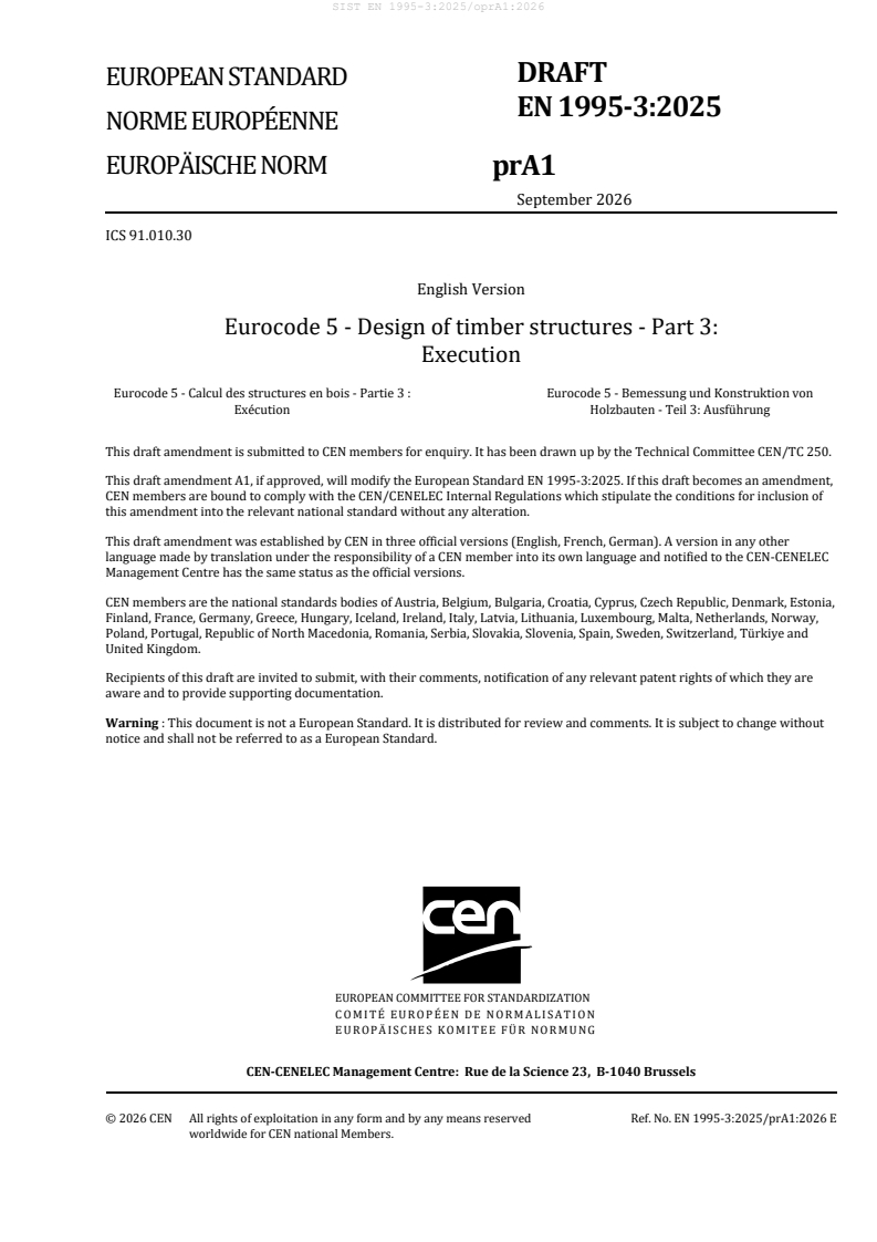
DRAFT
EUROPEAN STANDARD
EN 1995-3:2025
NORME EUROPÉENNE
EUROPÄISCHE NORM
prA1
September 2026
ICS 91.010.30
English Version
Eurocode 5 - Design of timber structures - Part 3:
Execution
Eurocode 5 - Calcul des structures en bois - Partie 3 : Eurocode 5 - Bemessung und Konstruktion von
Exécution Holzbauten - Teil 3: Ausführung
This draft amendment is submitted to CEN members for enquiry. It has been drawn up by the Technical Committee CEN/TC 250.
This draft amendment A1, if approved, will modify the European Standard EN 1995-3:2025. If this draft becomes an amendment,
CEN members are bound to comply with the CEN/CENELEC Internal Regulations which stipulate the conditions for inclusion of
this amendment into the relevant national standard without any alteration.
This draft amendment was established by CEN in three official versions (English, French, German). A version in any other
language made by translation under the responsibility of a CEN member into its own language and notified to the CEN-CENELEC
Management Centre has the same status as the official versions.
CEN members are the national standards bodies of Austria, Belgium, Bulgaria, Croatia, Cyprus, Czech Republic, Denmark, Estonia,
Finland, France, Germany, Greece, Hungary, Iceland, Ireland, Italy, Latvia, Lithuania, Luxembourg, Malta, Netherlands, Norway,
Poland, Portugal, Republic of North Macedonia, Romania, Serbia, Slovakia, Slovenia, Spain, Sweden, Switzerland, Türkiye and
United Kingdom.
Recipients of this draft are invited to submit, with their comments, notification of any relevant patent rights of which they are
aware and to provide supporting documentation.
Warning : This document is not a European Standard. It is distributed for review and comments. It is subject to change without
notice and shall not be referred to as a European Standard.
EUROPEAN COMMITTEE FOR STANDARDIZATION
COMITÉ EUROPÉEN DE NORMALISATION
EUROPÄISCHES KOMITEE FÜR NORMUNG
CEN-CENELEC Management Centre: Rue de la Science 23, B-1040 Brussels
© 2026 CEN All rights of exploitation in any form and by any means reserved Ref. No. EN 1995-3:2025/prA1:2026 E
worldwide for CEN national Members.
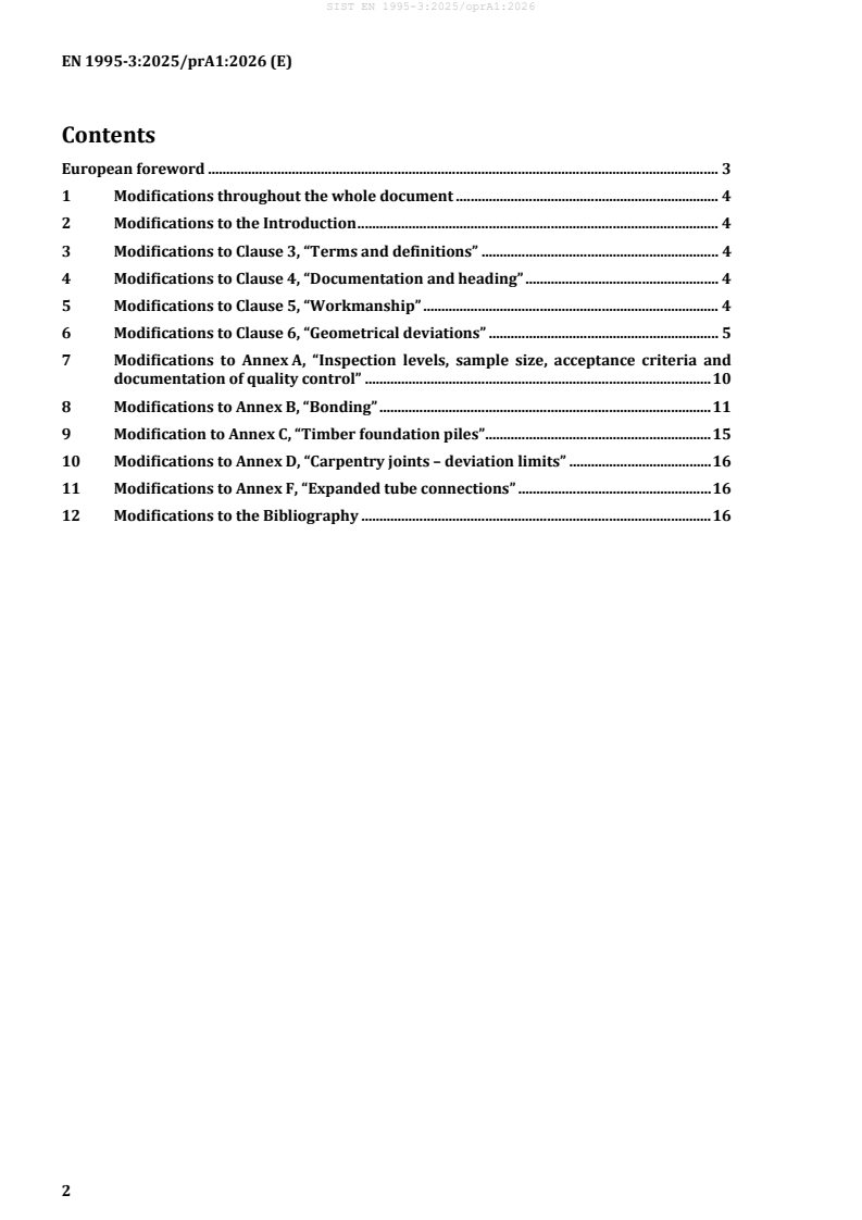
Contents
European foreword . 3
1 Modifications throughout the whole document . 4
2 Modifications to the Introduction . 4
3 Modifications to Clause 3, “Terms and definitions” . 4
4 Modifications to Clause 4, “Documentation and heading” . 4
5 Modifications to Clause 5, “Workmanship” . 4
6 Modifications to Clause 6, “Geometrical deviations” . 5
7 Modifications to Annex A, “Inspection levels, sample size, acceptance criteria and
documentation of quality control” . 10
8 Modifications to Annex B, “Bonding” . 11
9 Modification to Annex C, “Timber foundation piles” . 15
10 Modifications to Annex D, “Carpentry joints – deviation limits” . 16
11 Modifications to Annex F, “Expanded tube connections” . 16
12 Modifications to the Bibliography . 16
European foreword
This document (EN 1995-3:2025/prA1:2026) has been prepared by Technical Committee CEN/TC 250
“Structural Eurocodes”, the secretariat of which is held by BSI. CEN/TC 250 is responsible for all
Structural Eurocodes and has been assigned responsibility for structural and geotechnical design matters
by CEN.
This document is currently submitted to the CEN Enquiry.
This document will amend EN 1995-3:2025.
NOTE Some modifications are purely editorial corrections to improve the quality of the document and these
will not be tagged in the consolidated publication, as noted after the modification.
The first generation of EN Eurocodes was published between 2002 and 2007. This document forms part
of the second generation of the Eurocodes, which have been prepared under Mandate M/515 issued to
CEN by the European Commission and the European Free Trade Association.
The Eurocodes have been drafted to be used in conjunction with relevant execution, material, product
and test standards, and to identify requirements for execution, materials, products and testing that are
relied upon by the Eurocodes.
The Eurocodes recognize the responsibility of each Member State and have safeguarded their right to
determine values related to regulatory safety matters at national level through the use of National
Annexes.
1 Modifications throughout the whole document
Replace “EN 1990” with “EN 1990-1” except for the reference to “EN 1990” in 0.1
Replace “EN 1990:2023” with “EN 1990-1:2023+A1:2026”.
2 Modifications to the Introduction
In 0.2, replace “CEN/TS 19103 Eurocode 5 — Design of Timber Structures — Structural design of timber-
concrete composite structures — Common rules and rules for buildings” with “EN 1995-1-3 , Eurocode
5 — Design of timber structures — Part 1-3: Timber-concrete composite structures”.
In 0.3, in the first sentence of the second paragraph, replace “To achieve these functions,” with “It is
assumed that” and “needs to be” with “is”.
3 Modifications to Clause 3, “Terms and definitions”
In 3.1.3, in Note 1 to entry, delete “the execution specification,”.
In 3.2.5, add the following abbreviations: “GYP Gypsum based”, “STB Strand-based”, “SWB Solid-wood-
based”, “WFB Wood-fibre-based” and “WPB Wood-particle-based”.
4 Modifications to Clause 4, “Documentation and heading”
In 4.1(1), delete “and should be selected” replace “, where relevant,” with “(where relevant)”.
In 4.2(2), in d), delete “and for the sequence of erection including the need for an erection plan and
temporary support for stability as the erection proceeds”. In e), add “including” before “identification”.
After d), add “e) special requirements for the sequence of erection including the need for an erection
plan”; and “f) temporary support for stability as the erection proceeds”; and renumber the subsequent list
items.
In 4.3, replace “assurance” with “management” in the title.
In 4.3(2), in the second bullet point, replace “enabling the” with “ensuring” and “satisfactory quality of
materials” with “adequate material quality” and delete “the” before “execution”. In the note, replace “is an
example of an acceptable basis for” with “describes”.
In 4.4, replace “erection” with “during execution” in the title.
In 4.4, replace d) with “deviations from structural details, including e.g. number and specification of
fasteners, sizes of predrilled holes, and also checking that geometrical deviations from the spacings, edge
and end distances are within the deviation limits”;.
In 4.6(2), replace “The” with “Corrective measures shall be agreed with the” and delete “should be
informed and corrective measures shall be agreed”.
5 Modifications to Clause 5, “Workmanship”
Delete 5.1(1) and renumber the subsequent paragraphs.
Replace 5.1(2) with “Provisions of this standard and the manufacturer's instructions and the execution
specification, if any, shall be applied.”
In 5.2, delete “plan” from the title.
In development, currently at Enquiry stage
In 5.2(1), replace “should be prepared” with “shall be prepared, including the sequence of erection of parts
of the structure and the need for any temporary bracing”.
Delete 5.2(2) and renumber the subsequent paragraphs.
In 5.2(3), delete “together”.
In 5.3(1), replace “should be prepared to achieve the following objectives” with “shall be prepared and
satisfy (2) to (4).”
In 5.3(3), in the second bullet point, replace “erection” with “construction”.
In 5.3(4), delete the second sentence.
In 5.4.1(1), replace “dowel-type fasteners” with “fasteners and connectors”.
In 5.4.2, add “(6) To reduce the risk of hydrogen embrittlement and also of increasing stresses in the
fastener due to swelling of the timbers, measures should be taken to reduce the risk of wetting during
storage and erection.”
In 5.4.3, add “mechanical” before “connections” in the title.
In 5.4.3(1), replace “material” with “component or element”.
In 5.4.3(2), replace “should” with “shall”.
In 5.4.3(6), replace “in order to” with “to” and “at the bottom edge of PLY” with “along the edges of PW”.
In 5.4.3(8), replace “Slots” with “Circular grooves” and “produced” with “cut”.
Renumber 5.5 as 5.4.4.
In former 5.5(1), replace “should” with “shall”.
6 Modifications to Clause 6, “Geometrical deviations”
In 6.1.1(1), delete the second sentence.
Replace 6.1.1(2) with “The measuring device used shall be recorded and the accuracy of the method may
be noted.”
In 6.3(2), add note “NOTE 3 The deviation limits given in Table 6.2 are for horizontal plate members; those
for vertical plate members are found by replacing width b with height h and depth h with thickness t.”
In Figure 6.1, replace subfigure b) with the updated figure.
Replace Table 6.1 with:
Cut/machined Diagram Δ [mm]
max
geometry
a
1 Length ±max{5;l/1000}
b
2 Pressure contact ±max{2;(h + b)/1000}
(e.g. bearing, butt
joint, carpentry
connections)
3 Slots for steel plates Slot width b :
sl
t ≤ b ≤ t + max{h /150;
s sl s s
ls/150; 3}
Edge distances of slots or
distances between slots b
i
(i = 1, 2, .):
±min{5; b /10}
i
4 Holes in beams Deviation limits for locating
dimensions h , h , l , or l :
rl ru A Z
±max{10; h /100}; or
rl
±max{10; h /100}; or
ru
±max{10; l /100}; or
A
±max{10; l /100};
Z
Deviation limits for hole
dimensions l , d or h :
h h
±max{5; l /50}; or
h
±max{5; h /50}; or
h
±max{5; d/50};
5 Notches Deviation limits for
dimensions (h–h ) or l :
ef 1
±max{5; (h–h )/100}, or
ef
±max{5; l /100}
Key
b width, in mm
b edge distance of slots or distance between slots (i = 1, 2 …), in mm
i
b slot width, in mm
sl
d diameter of a hole in a beam, in mm
h height, in mm
notch height, in mm
hef
h height of rectangular hole, in mm
h
h distance of lower hole to member edge, in mm
rl
h distance of upper hole to member edge, in mm
ru
h height of steel plate, in mm
s
l length, in mm
l distance of the hole edge to the centre of the support, in mm
A
l embedded length of steel plate in slot, mm
s
l distance between the edges of two holes, in mm
Z
l1 notch length, in mm
t thickness of steel plate, in mm
s
Δ deviation, in mm
a
As products are usually machined after being placed on the market, deviation limits in product specifications
can differ.
b
The suggested deviation limits can be increased for contact surfaces in bearing with the use of a cast filler
compound, subject to agreement with the party responsible for the structural design of the works. For
carpentry
...