

prEN 13799
(Main)LPG equipment and accessories - Contents gauges for Liquefied Petroleum Gas (LPG) pressure vessels
- Abstract
This document specifies minimum requirements for design and testing of contents gauges, which are directly connected to LPG transportable pressure vessels, LPG drums, LPG cylinders and static LPG pressure vessels above 0,5 l water capacity excluding those used for automotive containers.
This document includes minimum requirements for the safe interchangeability of telemetry equipment, which is either integral in or additional to the contents gauge.
This document does not apply to refineries or other process plants.
- Status
- Not Published
- Publication Date
- 21-Jul-2026
- Technical Committee
- CEN/TC 286 - Liquefied petroleum gas equipment and accessories

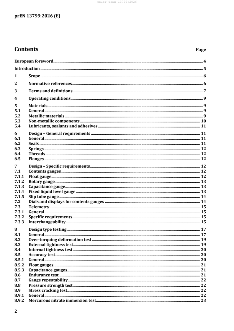
prEN 13799 is a draft European Standard from CEN for LPG equipment and accessories - contents gauges for Liquefied Petroleum Gas (LPG) pressure vessels. It specifies minimum requirements for the design, testing, marking and documentation of contents gauges, including the safe interchangeability of telemetry equipment, for manufacturers, test laboratories and users of LPG pressure equipment.
What does prEN 13799 specify?
prEN 13799 covers contents gauges that are directly connected to LPG transportable pressure vessels, LPG drums, LPG cylinders and static LPG pressure vessels above 0,5 l water capacity, excluding automotive containers. It also covers minimum requirements for telemetry equipment that is integral in, or added to, the contents gauge.
prEN 13799 does not apply to refineries or other process plants. The document is organised into clauses 1 to 11, with Annexes A to D and Annex ZA.
| Annex | What it covers |
|---|---|
| Annex A | Float gauge flange and gasket nominal dimensions |
| Annex B | Special low temperature requirements |
| Annex C | Production testing and inspection |
| Annex D | Vibration testing |
| Annex ZA | Relationship with the essential requirements of EU Directive 2014/68/EU |
What are the key requirements of prEN 13799?
Operating conditions and materials
prEN 13799 sets the environmental and pressure limits that the gauge has to withstand in service. It requires suitability from -20 °C, with a lower limit of -40 °C for severe European temperature conditions, up to 65 °C, and it sets the maximum allowable pressure at 30 bar. In practice, this means the designer has to choose materials, seals and constructions that stay functional in cold weather, hot weather and vacuum exposure.
Clause 5 requires LPG-compatible materials throughout the wetted parts and the normal operating range. Metallic materials include steel, stainless steel, copper alloys, aluminium alloys, zinc alloys and spheroidal graphite cast iron, with additional conditions for flanges, stainless steel content, brass, zinc alloys and propane flanges. Non-metallic parts, especially rubber materials and floats, have to resist LPG, ageing, lubricants and, where relevant, ozone and condensate. This matters because the gauge must keep its shape, buoyancy, sealing and strength over its service life.
General design and connection requirements
Clause 6 requires moving parts to move freely, all functional parts to be secured against accidental disassembly, and the design to maintain both external and internal leak tightness during transport vibration. Where the gauge includes electrical equipment, it must be explosion proof or intrinsically safe and meet EN IEC 60079-0. That is important because the gauge is installed on a pressure vessel that may be handled, moved and used in hazardous areas.
Threads and flanges are treated as safety-critical interfaces. Taper threaded pressure vessel connections have to comply with ANSI/ASME B1.20.1 and include design features that prevent over-torquing from harming function; other threads must follow EN or ISO standards, and ISO 7-1:1994 is excluded to avoid mismatch. Flanges must follow Annex A or EN 1092-1. In practice, this is about getting the connection right so the gauge can be installed, sealed and serviced without damaging the vessel connection.
Gauge-specific requirements and telemetry
Clause 7 sets different technical expectations for float, rotary, capacitance, fixed liquid level and slip tube gauges. It includes requirements for dial replacement, correct orientation, secure mounting screws, safe removal and replacement under pressure, protected venting, and limits on the way each gauge measures or indicates contents. The document also sets accuracy expectations for the different types, so the user can rely on the reading for filling and use.
Telemetry is covered as a separate function. prEN 13799 says telemetry must not interfere with filling, maintenance, visibility or gauge function, and it must not reduce the accuracy of the visual reading. Where telemetry is added to an existing gauge, the interchangeability requirements in 7.3.3 apply, including the geometry and magnetic coupling of the dial insert. In practice, this lets manufacturers and users add remote reading without losing compatibility with the base gauge.
Type testing and production control
Clause 8 defines the design type tests used to prove the design. These include over-torquing deformation, external and internal tightness, accuracy, endurance, repeatability, pressure strength, stress cracking, vacuum, float tests and a dial insert pressure test. Table 1 shows which tests apply to each gauge type, and Annex D gives an optional vibration test for transport use. This is the qualification stage, where the design has to prove it can survive service conditions before production release.
Clause 9 and Annex C cover production testing and inspection. Every gauge is subject to production leak testing, and batches are sampled using ISO 2859-1 for checks such as operation, dimensions, material suitability and marking. That matters for quality management because it sets the routine checks that support consistent manufacture, not just one-off type approval.
Marking and delivery information
Clause 10 requires each contents gauge to be permanently marked with the manufacture date, type or reference, manufacturer identification, PS 30 bar, and the minimum and maximum design temperatures. Gauges that meet Annex B also need the “-40 °C” marking. Clause 11 requires delivery information such as operating instructions, allowable limits, performance characteristics, installation instructions, flange and thread torque information, type identification, manufacturer details and maintenance guidance. This is what installers, inspectors and operators need to fit and use the gauge correctly.
What terms does prEN 13799 define?
- LPG - low pressure gas made mainly of propane, propene, butane, butane isomers and butene, and assigned to the listed UN numbers.
- contents gauge - a device that indicates the liquid level or contents in a pressure vessel.
- float gauge - a contents gauge that uses a float on the liquid surface inside the vessel.
- capacitance gauge - a gauge that measures liquid level using a very low voltage capacitance probe.
- rotary gauge - a gauge that uses a rotating action and temporary venting to detect the change from liquid to vapour.
- fixed liquid level gauge - a control device that indicates a predetermined liquid level when vented LPG changes from vapour to liquid.
- slip tube - a device that uses linear movement and temporary venting to detect the change from liquid to vapour.
Who uses prEN 13799?
prEN 13799 is used by manufacturers of LPG contents gauges, dial assemblies, floats and telemetry equipment, because it sets the design and test basis for their products. It is also used by LPG cylinder, drum and pressure vessel manufacturers, test laboratories, conformity assessment bodies, quality managers and inspectors who need to verify leak tightness, strength, accuracy and marking.
Buyers and technical teams in LPG storage, transport and distribution use it when specifying a compatible gauge for a vessel, especially where remote reading or transport vibration is involved. Maintenance and reconditioning teams use it to understand the required instructions, limits and replacement conditions.
What changed in prEN 13799 from the previous edition?
prEN 13799 supersedes EN 13799:2022. The main change stated for this edition is the introduction of capacitance level measurement technology.
Which standards are used with prEN 13799?
prEN 13799 relies on a set of standards for materials, sealing, testing and hazardous-area equipment. The most relevant ones are:
- EN 549 - rubber materials for seals and diaphragms used in gas equipment.
- EN 751-1, EN 751-2, EN 751-3 - sealing materials for metallic threaded joints.
- EN 1092-1 - steel flanges for pressure connections.
- EN 12516-1 and EN 12516-4 - body material selection for pressurised parts.
- EN 13445-2 - material requirements for unfired pressure vessels.
- EN 13906-1 - design of compression springs.
- EN IEC 60079-0 - general requirements for electrical equipment in explosive atmospheres.
- EN 1779 - leak testing method selection.
- EN 2859-1 - sampling by attributes for batch inspection.
- ISO 1817 - liquid resistance testing for rubber.
- ISO 6957 - ammonia stress corrosion testing for copper alloys.
- ANSI/ASME B1.20.1 - taper pipe threads used for pressure vessel connections.
- EN ISO 11114-1 and EN ISO 11114-2 - compatibility guidance for metallic and non-metallic materials with gas contents.
- EN ISO 7049, UNI 8112 and DIN 7500 C - screw types used in the interchangeability details.
- EN 15940 - paraffinic diesel fuel, referenced for the capacitance-gauge test fluid.
What does the prEN 13799 document contain?
prEN 13799 contains a full test programme for design verification, including over-torquing, tightness, accuracy, endurance, pressure strength, stress cracking, vacuum and float performance tests. Table 1 maps those tests to each gauge type, while Tables 2 and 3 give the torque values and leakage test pressures used in the procedures.
The document also contains Annex A dimensional data for float gauge flanges and gaskets, Annex B low-temperature conditioning, Annex C production inspection steps, and Annex D a vibration test for transport conditions. Figure 1 shows the interchangeability arrangement for float gauge and capacitance gauge inserts, and Annex ZA links the document to Directive 2014/68/EU.
Relations
- Effective Date
- 05-Jun-2024
Get Certified
Connect with accredited certification bodies for this standard

Institut za varilstvo d.o.o. (Welding Institute)
Slovenia's leading welding institute since 1952. ISO 3834, EN 1090, pressure equipment certification, NDT personnel, welder qualification. Only IIW Au
Sponsored listings
Frequently Asked Questions
prEN 13799 is a draft published by the European Committee for Standardization (CEN). Its full title is "LPG equipment and accessories - Contents gauges for Liquefied Petroleum Gas (LPG) pressure vessels". This standard covers: This document specifies minimum requirements for design and testing of contents gauges, which are directly connected to LPG transportable pressure vessels, LPG drums, LPG cylinders and static LPG pressure vessels above 0,5 l water capacity excluding those used for automotive containers. This document includes minimum requirements for the safe interchangeability of telemetry equipment, which is either integral in or additional to the contents gauge. This document does not apply to refineries or other process plants.
This document specifies minimum requirements for design and testing of contents gauges, which are directly connected to LPG transportable pressure vessels, LPG drums, LPG cylinders and static LPG pressure vessels above 0,5 l water capacity excluding those used for automotive containers. This document includes minimum requirements for the safe interchangeability of telemetry equipment, which is either integral in or additional to the contents gauge. This document does not apply to refineries or other process plants.
prEN 13799 is classified under the following ICS (International Classification for Standards) categories: 23.020.01 - Fluid storage devices in general. The ICS classification helps identify the subject area and facilitates finding related standards.
prEN 13799 has the following relationships with other standards: It is inter standard links to EN 13799:2022. Understanding these relationships helps ensure you are using the most current and applicable version of the standard.
prEN 13799 is associated with the following European legislation: EU Directives/Regulations: 2008/68/EC, 2014/68/EU; Standardization Mandates: M/071, M/601, M/TDG. When a standard is cited in the Official Journal of the European Union, products manufactured in conformity with it benefit from a presumption of conformity with the essential requirements of the corresponding EU directive or regulation.
prEN 13799 is available in PDF format for immediate download after purchase. The document can be added to your cart and obtained through the secure checkout process. Digital delivery ensures instant access to the complete standard document.
Standards Content (Sample)
SLOVENSKI STANDARD
01-december-2026
Oprema in pribor za utekočinjeni naftni plin (UNP) - Kazalniki nivoja v posodah za
UNP
LPG equipment and accessories - Contents gauges for Liquefied Petroleum Gas (LPG)
pressure vessels
Flüssiggas-Geräte und Ausrüstungsteile - Füllstandsanzeiger für Druckbehälter für
Flüssiggas (LPG)
Equipements pour GPL et leurs accessoires - Jauges de niveau pour les réservoirs de
gaz de pétrole liquéfié (GPL)
Ta slovenski standard je istoveten z: prEN 13799
ICS:
23.020.10 Nepremične posode in Stationary containers and
rezervoarji tanks
2003-01.Slovenski inštitut za standardizacijo. Razmnoževanje celote ali delov tega standarda ni dovoljeno.
DRAFT
EUROPEAN STANDARD
NORME EUROPÉENNE
EUROPÄISCHE NORM
December 2026
ICS 23.020.01 Will supersede EN 13799:2022
English Version
LPG equipment and accessories - Contents gauges for
Liquefied Petroleum Gas (LPG) pressure vessels
Equipements pour GPL et leurs accessoires - Jauges de Flüssiggas-Geräte und Ausrüstungsteile -
niveau pour les réservoirs de gaz de pétrole liquéfié Füllstandsanzeiger für Druckbehälter für Flüssiggas
(GPL) (LPG)
This draft European Standard is submitted to CEN members for enquiry. It has been drawn up by the Technical Committee
CEN/TC 286.
If this draft becomes a European Standard, CEN members are bound to comply with the CEN/CENELEC Internal Regulations
which stipulate the conditions for giving this European Standard the status of a national standard without any alteration.
This draft European Standard was established by CEN in three official versions (English, French, German). A version in any other
language made by translation under the responsibility of a CEN member into its own language and notified to the CEN-CENELEC
Management Centre has the same status as the official versions.
CEN members are the national standards bodies of Austria, Belgium, Bulgaria, Croatia, Cyprus, Czech Republic, Denmark,
Estonia, Finland, France, Germany, Greece, Hungary, Iceland, Ireland, Italy, Latvia, Lithuania, Luxembourg, Malta, Netherlands,
Norway, Poland, Portugal, Republic of North Macedonia, Romania, Serbia, Slovakia, Slovenia, Spain, Sweden, Switzerland, Türkiye
and United Kingdom.
Recipients of this draft are invited to submit, with their comments, notification of any relevant patent rights of which they are
aware and to provide supporting documentation.
Warning : This document is not a European Standard. It is distributed for review and comments. It is subject to change without
notice and shall not be referred to as a European Standard.
EUROPEAN COMMITTEE FOR STANDARDIZATION
C O M I T É E U R O P É E N D E N O R M A L I S A T I O N
E U R O P Ä I S C H E S K O M I T E E F Ü R N O R M U N G
CEN-CENELEC Management Centre: Rue de la Science 23, B-1040 Brussels
© 2026 CEN All rights of exploitation in any form and by any means reserved Ref. No. prEN 13799:2026 E
worldwide for CEN national Members.
Contents Page
European foreword . 4
Introduction . 5
1 Scope . 6
2 Normative references . 6
3 Terms and definitions . 7
4 Operating conditions . 9
5 Materials . 9
5.1 General . 9
5.2 Metallic materials . 9
5.3 Non-metallic components . 10
5.4 Lubricants, sealants and adhesives . 11
6 Design – General requirements . 11
6.1 General . 11
6.2 Seals . 11
6.3 Springs . 12
6.4 Threads . 12
6.5 Flanges . 12
7 Design – Specific requirements . 12
7.1 Contents gauges . 12
7.1.1 Float gauge . 12
7.1.2 Rotary gauge . 13
7.1.3 Capacitance gauge . 13
7.1.4 Fixed liquid level gauge . 13
7.1.5 Slip tube gauge . 14
7.2 Dials and displays for contents gauges . 14
7.3 Telemetry . 15
7.3.1 General . 15
7.3.2 Specific requirements . 15
7.3.3 Interchangeability . 15
8 Design type testing . 17
8.1 General . 17
8.2 Over-torquing deformation test . 19
8.3 External tightness test . 19
8.4 Internal tightness test . 20
8.5 Accuracy test . 20
8.5.1 General . 20
8.5.2 Float gauges . 21
8.5.3 Capacitance gauges . 21
8.6 Endurance test . 21
8.7 Gauge repeatability . 22
8.8 Pressure strength test . 22
8.9 Stress cracking test . 22
8.9.1 General . 22
8.9.2 Mercurous nitrate immersion test . 23
8.9.3 Moist ammonia air stress cracking test . 23
8.10 Float pressure test . 23
8.11 Dimensional inspection . 23
8.12 Function test . 23
8.13 Vacuum test . 23
8.14 Float test. 23
8.14.1 Resistance to gas . 23
8.14.2 Resistance to condensate/liquid phase of combustible gases . 24
8.15 Dial insert pressure test . 24
9 Production testing and inspection . 25
9.1.1 Contents gauges . 25
9.1.2 Castings . 25
10 Marking . 25
11 Documentation . 25
Annex A (normative) Float gauge flange and gasket nominal dimensions . 27
Annex B (normative) Special low temperature requirements . 30
Annex C (normative) Production testing and inspection . 31
C.1 General . 31
C.2 Production testing . 31
C.3 Batch testing . 31
C.4 Rejection criteria . 31
C.5 Finishing operations . 32
Annex D (informative) Vibration testing . 33
D.1 General . 33
D.2 Test samples . 33
D.3 Test method . 33
D.4 Criteria for passing the test . 33
Annex ZA (informative) Relationship between this European Standard and the essential
requirements of EU Directive 2014/68/EU aimed to be covered . 34
Bibliography . 36
European foreword
This document (prEN 13799:2026) has been prepared by Technical Committee CEN/TC 286 “Liquid gas
equipment and accessories”, the secretariat of which is held by NSAI.
This document is currently submitted to the CEN Enquiry.
This document supersedes EN 13799:2022.
The main changes compared to the previous edition include:
— introduction of capacitance level measurement technology.
This document has been submitted for reference in:
— the RID [2];
— the technical annexes of the ADR [3].
NOTE These regulations take precedence over any clause of this document. It is emphasized that RID/ADR are
being revised regularly at intervals of two years which might lead to temporary non-compliances with the clauses
of this document.
This document has been prepared under a standardization request addressed to CEN by the European
Commission. The Standing Committee of the EFTA States subsequently approves these requests for its
Member States.
For the relationship with EU Legislation, see informative Annex ZA, which is an integral part of this
document.
For the purposes of this document, contents gauges are considered a pressure accessory in accordance
with the Pressure Equipment Directive 2014/68/EU [1] in that they have a function additional to that of
containing pressure.
Any feedback and questions on this document should be directed to the users’ national standards body.
A complete listing of these bodies can be found on the CEN website.
Introduction
Provisions are restricted to a general guidance. Limit values are specified in national laws. It is
recommended that companies using this document develop an environmental management policy. For
guidance see the ISO 14000 series [8].
Protection of the environment is a key political issue in Europe and elsewhere. For TC 286 this is covered
in CEN/TS 16765 [4] LPG equipment and accessories - Environmental considerations for CEN/TC 286
standards, and this Technical Specification should be read in conjunction with this document. This
Technical Specification provides guidance on the environmental aspects to be considered regarding
equipment and accessories produced for the LPG industry and the following is addressed:
a) design;
b) manufacture;
c) packaging;
d) use and operation;
e) disposal.
In this document the unit bar is used, due to its universal use in the field of technical gases. It should,
however, be noted that bar is not an SI unit, and that the corresponding SI unit for pressure is Pa
5 5 2
(1 bar = 10 Pa = 10 N/m ).
NOTE Pressure values given in this document are given as gauge pressure (pressure exceeding atmospheric
pressure) unless otherwise stated.
1 Scope
This document specifies minimum requirements for design and testing of contents gauges, which are
directly connected to LPG transportable pressure vessels, LPG drums, LPG cylinders and static LPG
pressure vessels above 0,5 l water capacity excluding those used for automotive containers.
This document includes minimum requirements for the safe interchangeability of telemetry equipment,
which is either integral in or additional to the contents gauge.
This document does not apply to refineries or other process plants.
2 Normative references
The following documents are referred to in the text in such a way that some or all of their content
constitutes requirements of this document. For dated references, only the edition cited applies. For
undated references, the latest edition of the referenced document (including any amendments) applies.
EN 549:2019+A2:2024, Rubber materials for seals and diaphragms for gas appliances and gas equipment
EN 751-1:1996, Sealing materials for metallic threaded joints in contact with 1st, 2nd and 3rd family gases
and hot water — Part 1: Anaerobic jointing compounds
EN 751-2:1996, Sealing materials for metallic threaded joints in contact with 1st, 2nd and 3rd family gases
and hot water — Part 2: Non-hardening jointing compounds
EN 751-3:2022+A1:2023, Sealing materials for metallic threaded joints in contact with 1st, 2nd and 3rd
family gases and hot water — Part 3: PTFE tapes and PTFE strings
EN 1092-1:2018, Flanges and their joints — Circular flanges for pipes, valves, fittings and accessories, PN
designated — Part 1: Steel flanges
EN 1563:2018, Founding — Spheroidal graphite cast irons
EN 1774:1997, Zinc and zinc alloys — Alloys for foundry purposes — Ingot and liquid
EN 1779:2026, Non destructive testing — Leak testing — Criteria for method and technique selection
EN 12164:2024, Copper and copper alloys — Rod for free machining purposes
EN 12165:2024, Copper and copper alloys — Wrought and unwrought forging stock
EN 12420:2024, Copper and copper alloys — Forgings
EN 12516-1:2014+A1:2018, Industrial valves — Shell design strength — Part 1: Tabulation method for
steel valve shells
EN 12516-4:2014+A1:2018, Industrial valves — Shell design strength — Part 4: Calculation method for
valve shells manufactured in metallic materials other than steel
EN 13445-2:2026, Unfired pressure vessels — Part 2: Materials
EN 13906-1:2013, Cylindrical helical springs made from round wire and bar — Calculation and design —
Part 1: Compression springs
EN IEC 60079-0:2018, Explosive atmospheres — Part 0: Equipment — General requirements
(IEC 60079-0:2017)
ISO 301:2006, Zinc alloy ingots intended for castings
ISO 1817:2026, Rubber, vulcanized or thermoplastic — Determination of the effect of liquids
ISO 2859-1:2026, Sampling procedures for inspection by attributes — Part 1: Sampling schemes indexed by
acceptance quality limit (AQL) for lot-by-lot inspection
ISO 6957:1988, Copper alloys — Ammonia test for stress corrosion resistance
ANSI/ASME B1.20.1 - 2013, Pipe Threads, General Purpose (Inch)
3 Terms and definitions
For the purposes of this document, the following terms and definitions apply.
ISO and IEC maintain terminological databases for use in standardization at the following addresses:
— ISO Online browsing platform: available at https://www.iso.org/obp
— IEC Electropedia: available at https://www.electropedia.org/
3.1
LPG
low pressure gas composed of one or more light hydrocarbons which are assigned to UN 1011, UN 1075,
UN 1965, UN 1969 or UN 1978 only and which consists mainly of propane, propene, butane, butane
isomers, butene with traces of other hydrocarbon gases
3.2
contents gauge
device to indicate the liquid level or contents in a pressure vessel
3.2.1
float gauge
device to indicate the content of a vessel by means of a float on the liquid surface within the vessel
3.2.2
capacitance gauge
device which assesses the liquid level in a vessel using a very low voltage capacitance probe
3.2.3
rotary gauge
device which operates through a rotating action in order to assess the liquid level in a vessel by means of
temporarily venting a limited amount of LPG, whereupon the change from liquid to vapour is detected
This document is impacted by EN IEC 60079-0:2018/AC:2020-02 and EN IEC 60079-0:2018/A11:2024.
3.2.4
fixed liquid level gauge
control device which indicates the predetermined liquid level when there is a change in vented LPG from
vapour to liquid
EXAMPLE A dip tube in combination with a vent valve.
3.2.5
slip tube
device which operates through a linear action in order to assess the liquid level in a pressure vessel by
means of temporarily venting a limited amount of LPG, where upon the change from liquid to vapour is
detected
3.3
external leak tightness
resistance to leakage through the fitting to or from the atmosphere
3.4
internal leak tightness
resistance to leakage to atmosphere across the valve seal or any other pressure containing component
when the valve is closed
3.5
maximum allowable pressure
maximum pressure for which the equipment is designed
3.6
nominal diameter
DN
numerical designation of size, in millimetres, which is common to all components in a piping system other
than components designated by outside diameters or by thread size
Note 1 to entry: It is a convenient round number for reference purposes and is only loosely related to
manufacturing dimensions. The nominal size is designated by DN followed by a number.
3.7
pressure vessel
assembly of the pressure-retaining envelope (including the openings and their closures) and non-
pressure-retaining parts attached directly to it
3.8
type test
test or series of tests conducted to prove that the design meets the requirements of this document
4 Operating conditions
Contents gauges designed in accordance with this document shall be suitable for the following conditions:
— a minimum operating temperature of −20 °C;
— a minimum operating temperature of −40 °C for those parts of Europe where contents gauges are
subject to more severe temperature conditions. The material and design shall be shown to be
satisfactory for operations under these conditions and shall meet the requirements of Annex B;
— the maximum operating temperature is 65 °C;
— the minimum pressure to which a gauge is normally exposed is 0 bar gauge. Vacuum conditions on
the gauge, arising from butane at low temperature or evacuation of the pressure vessel can expose
the device to a vacuum of 0,05 bar absolute.
The maximum allowable pressure for a contents gauge shall be 30 bar.
5 Materials
5.1 General
5.1.1 All materials in contact with LPG shall be physically and chemically compatible with LPG under
all the normal operating conditions for which the contents gauge is intended to be used. Guidance for
compatibility is given in EN ISO 11114-1:2020 for metallic materials and EN ISO 11114-2:2021 for non-
metallic materials.
5.1.2 Materials for gauge components shall be selected to give adequate strength in service. Materials
selected shall adequately protect against other modes of failure such as atmospheric corrosion, brass
dezincification, stress corrosion or other material failure.
5.1.3 Alternative materials to those listed in 5.2 are not precluded, providing they comply with a
standard or specification that ensures control of chemical and physical properties, and quality
appropriate to the end use.
5.1.4 Dial inserts shall be sealed to prevent water ingress into the dial insert. The contents gauge shall
be designed to ensure that water ingress between the dial insert and gauge body is avoided or does not
interfere with the gauge operation if it freezes. This may include filling any void with suitable material or
the provision of a drain hole not less than 2,5 mm diameter.
5.1.5 Optional equipment directly connected to the gauge shall not affect the integrity of the gauge and
its function.
5.2 Metallic materials
5.2.1 Metallic materials for the pressurized parts of gauges shall be steel, stainless steel, copper alloys,
aluminium alloys, zinc alloys or spheroidal graphite cast iron and fulfil the following requirements:
a) body materials shall be selected in accordance with EN 12516-1:2014+A1:2018, EN 12516-
4:2014+A1:2018 or EN 13445-2:2026;
b) materials for steel flanges shall be in accordance with EN 1092-1:2018;
c) stainless steel for components shall contain not less than 16 % chromium, and not less than 6 %
nickel;
d) hot stamped brass shall be non-porous and suitable for machining or other processing. Leaded brass
shall be or CW617N in accordance with EN 12420:2024 and EN 12165:2024. Sand-cast brass shall
not be used;
e) cold drawn leaded brass rods shall be CW614N in accordance with EN 12164:2024. The brass rod
shall be free from stress in accordance with EN 12164:2024, 8.5;
f) sand-cast brass shall not be used;
g) spheroidal graphite cast iron shall comply with EN 1563:2018, with an elongation at fracture of more
than 18 %. Other ductile irons or cast irons shall not be used;
h) ZnAl4 and ZnAl4Cu1 shall be in accordance with ISO 301:2006 or EN 1774:1997;
i) for propane, flanges shall have a pressure rating of PN 40.
5.2.2 Metallic materials for the non-pressurized parts of gauges shall be steel, stainless steel, copper
alloys, aluminium alloys, or zinc alloys and fulfil the requirements a) to i) above, and:
a) springs shall be manufactured from stainless steel wire and shall contain not less than 16 %
chromium and not less than 6 % nickel.
5.2.3 Pressurized parts manufactured from hot stamped brass or contents gauge bodies made of drawn
brass or machined from brass rod shall be capable of withstanding, without cracking, the stress cracking
test in accordance with 8.9.
5.3 Non-metallic components
5.3.1 Non-metallic materials in contact with LPG shall not distort, harden or adhere to the gauge body
or seat face to such an extent as to impair the function of the gauge.
5.3.2 Rubber materials, with the exception of floats, in contact with LPG, for temperatures of –20 °C
(−40 °C for low temperature applications) to +65 °C, shall meet the requirements of
EN 549:2019+A2:2024 for resistance to:
a) gas (n-pentane test);
b) lubricants;
c) ageing;
d) compression;
e) ozone (where the material is exposed to the atmosphere);
f) condensate/liquid phase of combustible gases (liquid B test).
The ozone test in EN 549:2019+A2:2024 shall only be carried out where gaskets/seals are exposed to
atmosphere.
5.3.3 The buoyancy of the float shall not be adversely affected by the LPG. Non-metallic floats shall be
tested in accordance with 8.14 for resistance to gas and for resistance to condensate/liquid phase of
combustible gases.
5.4 Lubricants, sealants and adhesives
Where used on threads and seals; lubricants, sealants, and adhesives shall be compatible with LPG and
not interfere with the operation of the contents gauge. Sealants shall comply with EN 751-1:1996,
EN 751-2:1996 or EN 751-3:2022+A1:2023.
6 Design – General requirements
6.1 General
6.1.1 Moving parts shall have sufficient clearance to ensure freedom of movement under all normal
conditions of service. Means of guidance shall be provided to ensure correct operation.
6.1.2 All components necessary for the correct function of the device shall be secured to prevent
unintentional disassembly during normal operation.
6.1.3 Contents gauges shall be designed to ensure external and internal leak tightness, and their
function shall not be affected, as a result of vibration during transportation.
6.1.4 The design shall take account of the use of dissimilar materials, e.g. electrochemical corrosion or
material expansion.
6.1.5 Electrical equipment, when an integral part of the contents gauge, shall be either explosion proof
or intrinsically safe, and shall meet the requirements of EN IEC 60079-0:2018.
6.1.6 Contents gauges shall include all of the components necessary for their normal function and
installation on the pressure vessel.
6.1.7 Possible stress corrosion shall be eliminated by either design or heat treatment.
6.1.8 The design of the contents gauge should take account of the following:
— minimizing the use of materials;
— fittings required for the pressure vessel;
— minimizing the environmental impact of in-service maintenance and end of life disposal;
— efficient transport of finished product;
— any packaging and protection used during storage/transport of the finished product should be
selected to have the minimum environmental impact, i.e. use of recyclable or bio-degradable
materials, minimum use of energy.
6.2 Seals
Seals shall be attached or otherwise assembled such that they will not become dislocated under service
conditions. Dynamic seals shall not be secured solely by the application of adhesive.
6.3 Springs
Springs shall be designed in accordance with EN 13906-1:2013.
6.4 Threads
6.4.1 Taper threaded pressure vessel connections shall comply with ANSI/ASME B1.20.1 - 2013.
Thread sizes shall not exceed DN 50 (2 inches).
6.4.2 Where taper threads are used, the design shall ensure that over-torquing shall not impede the
correct operation of the contents gauge, see 8.2.
6.4.3 Taper threaded sections of a body designed for a pressure vessel connection shall be constructed
with wrenching flats.
6.4.4 All threads other than taper threaded pressure vessel connections shall be in accordance with a
European Standard (EN) or an International Standard (ISO), or should be in accordance with
ANSI/ASME B1.20.1 - 2013.
6.4.5 To avoid mismatching with ANSI/ASME B1.20.1 - 2013 threads, ISO 7-1:1994 [5] shall not be
used.
6.5 Flanges
Flanges shall comply with Annex A or with EN 1092-1:2018.
7 Design – Specific requirements
7.1 Contents gauges
7.1.1 Float gauge
7.1.1.1 The dial assembly, where applicable, shall be replaceable and the configuration for type 1 and
type 2 float gauges shall only permit the correct orientation of the dial assembly, see 7.3.3 for
interchangeability.
7.1.1.2 Stainless Steel socket head mounting screws shall be used with type 1 or type 2 float gauges
in accordance with Annex A, Figure A.1. Studs or stainless-steel socket head mounting screws shall be
used with type 3 or type 4 float gauges in accordance with Annex A, Figure A.2 (type 3) and Figure A.3
(type 4). The appropriate sealing gasket for the intended service condition shall be provided.
7.1.1.3 A hollow float or the material for a solid float shall comply with the following:
— retain buoyancy;
— withstand the normally expected variation in service conditions such as permanent immersion in
liquid/vapour LPG;
— withstand changes in relative density of the liquid;
— fulfil the requirements of 8.14.
7.1.1.4 Means shall be provided for the float gauge mechanism to operate correctly and continuously
over the full operating range. The operating mechanism shall be such that it cannot be damaged during
the filling of the pressure vessel.
7.1.1.5 Float gauges shall be designed to allow the safe removal and replacement of the dial, when
the vessel is under pressure, without disconnecting the gauge from the pressure vessel.
7.1.1.6 The dial insert shall be assembled to ensure that the internal atmosphere is clean dry air that
does not allow moisture to condense at any temperature between –40 °C and +65 °C.
7.1.1.7 In case of magnetic transmission, the float magnet and the dial magnet shall be such as to
transmit reliably, in all normal operating conditions, the level of liquid during the expected life of the
gauge.
7.1.1.8 The overall accuracy of the gauge from 31 % to 69 % of the vessel volume shall be ±5 %. The
accuracy of the gauge at ≤ 30 % and at ≥ 70 % the vessel volume shall be ±3 % throughout all scale
readings.
7.1.2 Rotary gauge
7.1.2.1 The cross-section of the passageway through the gauge body shall at some point be limited to
1,8 mm .
7.1.2.2 The vent screw shall remain captive or be permanently attached to the body.
7.1.2.3 The direction of the venting shall be away from the operator’s expected position.
7.1.2.4 The tube shall be of sufficient rigidity not to affect the accuracy of the gauge reading and be
capable of being rotated both clockwise and anticlockwise, through 360°.
7.1.2.5 The overall accuracy of the gauge shall be within ±2 %.
7.1.3 Capacitance gauge
7.1.3.1 A capacitance gauge shall operate by measurement of liquid dielectric through an electrically
powered sensing unit with no moving parts, powered and permanently installed into the tank with a
replaceable digital display to show the tank content.
7.1.3.2 The display assembly shall be replaceable and the configuration shall only permit the correct
orientation, as shown in Figure 1 a).
7.1.3.3 Stainless steel socket head screws shall be used in accordance with Annex A, Figure A.1.
7.1.3.4 The capacitance gauge shall be designed to allow safe removal and replacement of the display
assembly, when the vessel is under pressure, without disconnecting the gauge from the pressure vessel.
7.1.3.5 The overall accuracy of the capacitance gauge itself shall be ±1 %.
7.1.4 Fixed liquid level gauge
Fixed liquid level gauges shall meet the following requirements:
— the cross-section of the passageway through the gauge body shall at some point be limited to
1,8 mm ;
— the orifice shall be controlled by a vent screw;
— the vent screw shall remain captive, or be permanently attached to the gauge body;
— the direction of venting shall be away from the operator;
— the dip tube, where manufactured as an integral part of the gauge, shall be securely fastened;
— the length of the dip tube shall be determined in accordance with the maximum liquid filling level
depending on the grade of product and the operating conditions.
7.1.5 Slip tube gauge
7.1.5.1 The cross-section of the passageway through the gauge body shall at some point be limited to
1,8 mm .
7.1.5.2 The vent screw shall remain captive or be permanently attached to the body.
7.1.5.3 The design shall ensure that the slip tube cannot be removed from the body during normal
operation.
7.1.5.4 The slip tube shall maintain external tightness throughout its full operating range.
7.1.5.5 The overall accuracy of the gauge shall be within ±1 % throughout all scale readings of
pressure vessel volume.
7.2 Dials and displays for contents gauges
7.2.1 Dials and displays for contents gauges shall be designed so that they remain transparent and the
dial readings remain legible and visible throughout the service life of the gauge.
7.2.2 Dials or displays for contents gauges shall be designed to ensure the correct fitting and
orientation of the dial to the gauge.
7.2.3 Dials or displays shall be sealed to prevent ingress of water and internal components shall be
corrosion resistant or protected in accordance with 7.1.1.6.
7.2.4 The dial or display shall be designed to ensure that it reflects the position of the gauge.
7.2.5 The dial shall be manufactured from ultraviolet stabilizing material or protected so that dial
indication remains legible.
7.2.6 Where a dial is fixed using a threaded component, stainless steel shall be used.
7.2.7 Dial readings shall be expressed in percentages. The graduations shall not be greater than 5 %
and the labelling of the graduations shall not be greater than 10 % intervals for analogue dials and 1 %
intervals for digital dials. For vessels with a diameter below 600 mm, the marking may be shown as E,
1/4, 1/2, 3/4 and F with graduations every 1/8 volume for analogue dials.
On type 3 and type 4 gauges, gauge marking shall read in intervals of not greater than 1 % shown on the
dial.
7.2.8 For type 1 and type 2 float gauges on pressure vessels with a diameter of 600 mm and above, the
overfill gauge markings, including 85 % and above, shall be highlighted on the gauge.
7.2.9 For type 1 and type 2 float gauges on pressure vessels with a diameter of 600 mm and above, low
contents gauge readings including 20 % and below, shall also be highlighted in a distinct colour.
7.3 Telemetry
7.3.1 General
Telemetry is a technology for collecting contents gauge data/readings and transmitting the data to a
remote location by wire or wireless connection.
A telemetry system includes an electrically powered sensor, transmitter and receiver.
A telemetry system can be connected either on existing contents gauges installed on the pressure vessel,
or they can be additional to the contents gauge. When the system is additional to a contents gauge, it
requires a dial insert that can be safely interchanged with the contents gauge insert, see 7.3.3.
The telemetry system, when applied to a contents gauge, shall not interfere with its safe operation,
visibility, see 7.2.1, and functionality.
7.3.2 Specific requirements
Telemetry equipment when fitted shall not obstruct or interfere with the normal filling, operation and
maintenance of the pressure vessel.
Electrical parts of telemetry equipment used within a hazardous area shall be either explosion proof or
intrinsically safe and shall meet the requirements of EN IEC 60079-0:2018.
Telemetry equipment shall not reduce the accuracy of the visual readings of the original dial insert/gauge
combination.
7.3.3 Interchangeability
When considering the safe interchangeability of float gauge inserts and capacitance gauge inserts the
following requirements shall be met as illustrated in Figure 1:
a) the dial insert bolt circle diameter shall be between 47,6 mm and 48 mm for type 1 and 58,7 mm for
type 2, including 2 threaded screws at 3,5 mm × 9,5 mm, see EN ISO 7049:2011;
b) the two threaded screws may also be trilobated screws of 3,5 mm × 10 mm, see UNI 8112 or
DIN 7500 C;
c) the connecting points of a dial insert shall be distinguishable and shall accommodate orientation of
the dial insert, e.g. one lug can be rectangular in shape, while the other can be triangular in shape;
d) the dial insert diameter shall not exceed 40,6 mm for type 1 gauges and shall not exceed 51 mm for
type 2 gauges;
e) the contents gauge shall be provided with means to ensure water collection between the dial insert
and gauge does not accumulate and cause interference. This may include filling any void with suitable
material or the provision of a drain hole not less than 2,5 mm diameter;
f) the strength of the magnetic field of the dial insert in position “B” shall be a minimum of 110 G (Gauss)
and shall be sufficient to ensure engagement with its counterpart in the contents gauge. The strength
of the magnetic field of the dial insert shall not cause lift of the magnet in the contents gauge resulting
in abrasion or increased friction;
g) the strength of the magnetic field at the upper surface of the flange or head of the level gauge
(position “C”) shall be a minimum of 220 G (Gauss);
h) the depth distance (A) between the bottom of the dial insert and the upper face for the contents gauge
shall be not more than 2 mm;
i) a telemetry dial insert shall be a snug fit to any contents gauge to which it is fitted.
a) Float gauge insert
b) Float gauge detail
c) Capacitance gauge insert
Key
1 dial insert
2 contents gauge
A distance between bottom of the dial insert and upper face of contents gauge
B magnet
C magnet
Figure 1 — Interchangeability of a contents gauge
8 Design type testing
8.1 General
8.1.1 Samples, representative of the design, size and type shall be subjected to the type tests described
in Table 1. Samples of parts constructed of non-metallic materials shall be subjected to physical and
chemical tests, see 5.3.
8.1.2 Unless otherwise specified, tests shall be carried out at 20 °C ± 5 °C and ambient pressure.
8.1.3 All samples shall initially be subject to visual and dimensional inspection.
8.1.4 The tightness test method for 8.3 and 8.4 shall be in accordance with EN 1779:2026.
8.1.5 All pneumatic tightness and hydrostatic pressure strength tests shall be maintained for at least
2 min, unless specified otherwise in this document.
8.1.6 Test equipment connections shall be subject to dimensional inspection to ensure compatibility
with the test sample.
8.1.7 A sample design shall meet the requirements of this document only if it meets all the testing
requirements.
8.1.8 The following documents shall be available:
a) description of the sample and method of operation;
b) information on its field of application;
c) drawings consisting of the general plan, components and parts list;
d) testing procedure.
Table 1 — Design testing
Test Clause Fixed Rotary Float Slip tube Capacitanc
liquid gauge gauge e gauges
level
gauge
Over-torquing 8.2 X X O X X
deformation
External tightness 8.3 X X X X X
Internal tightness 8.4 X X N/A X N/A
Accuracy 8.5 N/A X X X X
Endurance 8.6 X X X X X
Repeatability 8.7 N/A X X X X
Pressure strength 8.8 X X X X X
Stress cracking 8.9 X X X X X
Float pressure 8.10 N/A N/A X N/A N/A
Dimensional 8.11 X X X X X
inspection
Function 8.12 X X X X X
Vacuum 8.13 X X X X X
Float 8.14 N/A N/A X N/A N/A
Dial insert 8.15 N/A N/A X N/A N/A
...