

FprEN IEC 63567-1:2026
(Main)Semiconductor devices - Performance evaluation of semiconductor processing components and inspection equipment - Part 1: Transmittance evaluation method of EUV pellicle
- Status
- Not Published
- Publication Date
- 07-Feb-2027
- Technical Committee
- CLC/TC 47X - Semiconductor devices and trusted chips
- Current Stage
- 5020 - Vote circulated - Formal Approval
- Start Date
- 25-Sep-2026
- Completion Date
- 25-Sep-2026

FprEN IEC 63567-1:2026 specifies a method for measuring the transmittance of extreme ultraviolet (EUV) pellicles used in extreme ultraviolet lithography (EUVL). It defines the measurement setup, specimen handling, calculation approach and test report content for single-pass and double-pass transmittance so laboratories, suppliers and buyers can compare results on the same basis.
What does FprEN IEC 63567-1:2026 specify?
FprEN IEC 63567-1:2026 covers EUV pellicles used on the front side of a reflective mask or reflective reticle to protect the mask from contaminant particles during EUV exposure. The document is organized into Clauses 1 to 8, with one informative annex.
| Part of the document | What it covers |
|---|---|
| Clause 1 | Scope for EUV pellicle transmittance measurement |
| Clause 2 | Normative references |
| Clause 3 | Terms, definitions, symbols and abbreviated terms |
| Clause 4 | Apparatus and measurement conditions |
| Clause 5 | Specimen preparation |
| Clause 6 | Transmittance evaluation process |
| Clause 7 | Transmittance calculation |
| Clause 8 | Test report |
| Annex A | Informative explanations and examples |
Clause 4 through Clause 7 are the practical core. They tell the reader how to set up the instrument, prepare the specimen, run the measurement and calculate the result in a way that matches EUVL use.
What are the key requirements of FprEN IEC 63567-1:2026?
Measurement apparatus
Clause 4 says the transmittance evaluation apparatus is built for both single-pass and double-pass measurement. FprEN IEC 63567-1:2026 requires EUV light in the same spectrum region as the EUV exposure tool, a high-vacuum environment, a pellicle positioning stage, a pellicle holder, EUV optics, a beam splitter (BS) and two detectors.
In practice, this means the test set-up must reproduce exposure-like conditions rather than using a general optical bench. The pellicle holder keeps the sample fixed, and the positioning stage supports transmittance mapping, defect location and cleaning-related checks.
Source condition, accuracy and noise control
Clause 4.3 requires a light source in the same EUV spectrum region as the exposure tool. Clause 4.4 sets the measurement accuracy target as a mean deviation of less than 0.1% across multiple measurements, as agreed by customer and supplier. Clause 4.5 says noise such as dark current shall be suppressed, for example by cooling the detector.
For the reader, this means the measurement result depends on stable source power, low detector noise and a suitable signal-to-noise ratio. The BS and two-detector arrangement are used to reduce the effect of source fluctuations on the result.
Specimen preparation
Clause 5.1 requires the pellicle membrane and frame to be visually clean and properly formed, with no membrane or frame extending beyond the frame wall and no visually detectable stringers, burrs, anodization irregularities or particles. Clause 5.2 sets storage at 21 ± 2 °C and 40 ± 15% relative humidity. Clause 5.3 requires at least 4 h of preconditioning in the measurement environment.
In practice, the specimen must be stabilized before test so that temperature and humidity do not distort the transmittance reading.
Measurement process and calculation
Clause 6 separates the method into double-pass and single-pass transmittance. The process first measures EUV power without the pellicle, then with the pellicle in place, and repeats the steps as agreed by customer and supplier.
Clause 7 defines transmittance as the ratio of power after passing through the pellicle to incident power. For double-pass transmittance, the calculation uses detector 1 and detector 2 data with BS correction for source fluctuation. For single-pass transmittance, the calculation uses the corresponding single-pass detector readings. The practical result is a transmittance value tied to the actual EUV exposure geometry.
Test report
Clause 8 requires the report to include the testing laboratory, the commissioning party, the test date and the specimen description. If the sample is damaged during measurement, the report shall also include a photograph of the damage and the cause.
What terms does FprEN IEC 63567-1:2026 define?
- Extreme ultraviolet lithography (EUVL) is pattern creation on semiconductor wafers using short-wavelength EUV light, such as 13.5 nm.
- Multilayer mirror (ML) is a mirror coated with alternating layers of two materials to reflect X-ray and EUV light efficiently.
- Chief ray of angle (CRA) is the angle of the central ray within a light cone.
- Pellicle is a protective film or membrane used to prevent contamination during the lithography process.
- Extreme ultraviolet mask is a reflective photomask with a multilayer and patterned absorber used in EUVL.
- Full-size pellicle is a pellicle covering the full photomask area.
- Coupon-size pellicle is a smaller pellicle used for testing membrane properties.
- Single-pass transmittance is the ratio of photons passing through the material once to incident photons.
- Double-pass transmittance is the ratio of photons passing through the material twice to incident photons.
Who uses FprEN IEC 63567-1:2026?
FprEN IEC 63567-1:2026 is used by laboratories, pellicle suppliers, EUV lithography tool developers, semiconductor manufacturers and inspection equipment teams. They use it to measure pellicle transmittance, check uniformity, locate contamination defects, compare measurement methods and prepare test reports for customer-supplier review.
Quality and purchasing teams can also use it when they need a common method for requesting data or comparing pellicle lots. The value in practice is consistent communication about what was measured, under what EUV conditions and with what calculation method.
What does the FprEN IEC 63567-1:2026 document contain?
The document contains apparatus schematics, measurement-process diagrams and the calculation approach for both double-pass and single-pass transmittance. Figure 1 shows example apparatus layouts, and Figure 2 shows the measurement sequence.
Table 1 lists the symbols and abbreviated terms used in the method. Annex A gives explanatory material, including example pellicle images, scanning-method results and point-to-point results, which help readers understand how the method is applied to real samples.
The bibliography points to other IEC publications on optical transmittance measurement, which can be useful for readers comparing methods across different materials and applications.
Frequently Asked Questions
FprEN IEC 63567-1:2026 is a draft published by CLC. Its full title is "Semiconductor devices - Performance evaluation of semiconductor processing components and inspection equipment - Part 1: Transmittance evaluation method of EUV pellicle". This standard covers: Semiconductor devices - Performance evaluation of semiconductor processing components and inspection equipment - Part 1: Transmittance evaluation method of EUV pellicle
Semiconductor devices - Performance evaluation of semiconductor processing components and inspection equipment - Part 1: Transmittance evaluation method of EUV pellicle
FprEN IEC 63567-1:2026 is classified under the following ICS (International Classification for Standards) categories: 31.080.99 - Other semiconductor devices. The ICS classification helps identify the subject area and facilitates finding related standards.
FprEN IEC 63567-1:2026 is available in PDF format for immediate download after purchase. The document can be added to your cart and obtained through the secure checkout process. Digital delivery ensures instant access to the complete standard document.
Standards Content (Sample)
SLOVENSKI STANDARD
oSIST prEN IEC 63567-1:2026
01-februar-2026
Polprevodniški elementi - Vrednotenje učinkovitosti komponent za obdelavo
polprevodnikov in opreme za pregledovanje - 1. del: Metoda ocenjevanja
prepustnosti pelikule EUV
Semiconductor devices - Performance evaluation of semiconductor processing
components and inspection equipment - Part 1: Transmittance evaluation method of
EUV pellicle
Ta slovenski standard je istoveten z: prEN IEC 63567-1:2025
ICS:
31.080.99 Drugi polprevodniški elementi Other semiconductor devices
oSIST prEN IEC 63567-1:2026 en
2003-01.Slovenski inštitut za standardizacijo. Razmnoževanje celote ali delov tega standarda ni dovoljeno.
oSIST prEN IEC 63567-1:2026
oSIST prEN IEC 63567-1:2026
47/2976/CDV
COMMITTEE DRAFT FOR VOTE (CDV)
PROJECT NUMBER:
IEC 63567-1 ED1
DATE OF CIRCULATION: CLOSING DATE FOR VOTING:
2025-12-19 2026-03-13
SUPERSEDES DOCUMENTS:
47/2860/CD, 47/2935/CC
IEC TC 47 : SEMICONDUCTOR DEVICES
SECRETARIAT: SECRETARY:
Korea, Republic of Mr Cheolung Cha
OF INTEREST TO THE FOLLOWING COMMITTEES: HORIZONTAL FUNCTION(S):
ASPECTS CONCERNED:
SUBMITTED FOR CENELEC PARALLEL VOTING NOT SUBMITTED FOR CENELEC PARALLEL VOTING
Attention IEC-CENELEC parallel voting
The attention of IEC National Committees, members of
CENELEC, is drawn to the fact that this Committee Draft
for Vote (CDV) is submitted for parallel voting.
The CENELEC members are invited to vote through the
CENELEC online voting system.
This document is still under study and subject to change. It should not be used for reference purposes.
Recipients of this document are invited to submit, with their comments, notification of any relevant patent rights of
which they are aware and to provide supporting documentation.
Recipients of this document are invited to submit, with their comments, notification of any relevant “In Some
Countries” clauses to be included should this proposal proceed. Recipients are reminded that the CDV stage is
the final stage for submitting ISC clauses. (SEE AC/22/2007 OR NEW GUIDANCE DOC).
TITLE:
Semiconductor devices - Performance evaluation of semiconductor processing components
and inspection equipment - Part 1: Transmittance evaluation method of EUV pellicle
PROPOSED STABILITY DATE: 2029
NOTE FROM TC/SC OFFICERS:
download this electronic file, to make a copy and to print out the content for the sole purpose of preparing National
Committee positions. You may not copy or "mirror" the file or printed version of the document, o r any part of it,
for any other purpose without permission in writing from IEC.
oSIST prEN IEC 63567-1:2026
IEC CDV 63567-1 © IEC 2025
1 CONTENTS
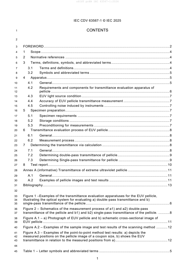
3 FOREWORD . 2
4 1 Scope . 4
5 2 Normative references . 4
6 3 Terms, definitions, symbols, and abbreviated terms . 4
7 3.1 Terms and definitions. 4
8 3.2 Symbols and abbreviated terms . 5
9 4 Apparatus . 5
10 4.1 General . 5
11 4.2 Requirements and components for transmittance evaluation apparatus of
12 pellicle . 6
13 4.3 EUV light source condition . 7
14 4.4 Accuracy of EUV pellicle transmittance measurement . 7
15 4.5 Controlling noise induced by instruments . 7
16 5 Specimen preparation . 7
17 5.1 Specimen requirements . 7
18 5.2 Storage conditions . 7
19 5.3 Preconditioning for measurements . 7
20 6 Transmittance evaluation process of EUV pellicle . 8
21 6.1 General . 8
22 6.2 Measurement process . 8
23 7 Determining the transmittance via calculation . 8
24 7.1 General . 8
25 7.2 Determining double-pass transmittance of pellicle . 9
26 7.3 Determining Single-pass transmittance for pellicle . 9
27 8 Test report . 10
28 Annex A (informative) Transmittance of extreme ultraviolet pellicle . 11
29 A.1 General . 11
30 A.2 Examples of pellicle images and test results . 11
31 Bibliography . 13
33 Figure 1 –Examples of the transmittance evaluation apparatuses for the EUV pellicle,
34 illustrating the optical system for evaluating a) double-pass transmittance and b)
35 single-pass transmittance of the pellicle . 6
36 Figure 2 – Schematics of the measurement process of a1) and a2) double-pass
37 transmittance of the pellicle and b1) and b2) single-pass transmittance of the pellicle. . 8
38 Figure A.1 – a) Photograph of EUV pellicle and b) schematic cross-sectional image of
39 EUV pellicle . 11
40 Figure A.2 – Examples of the sample image and test results of the scanning method . 12
41 Figure A.3 – Examples of the point-to-point method test results: a) depicts the
42 measured positions on the pellicle image of a coupon size, b) shows the EUV
43 transmittance in relation to the measured positions from a) . 12
45 Table 1 – Letter symbols and abbreviated terms . 5
oSIST prEN IEC 63567-1:2026
IEC CDV 63567-1 © IEC 2025
47 INTERNATIONAL ELECTROTECHNICAL COMMISSION
48 ____________
50 SEMICONDUCTOR DEVICES -
51 PERFORMANCE EVALUATION OF SEMICONDUCTOR PROCESSING
52 COMPONENTS AND INSPECTION EQUIPMENT
54 Part 1: Transmittance evaluation method of EUV pellicle
56 FOREWORD
57 1) The International Electrotechnical Commission (IEC) is a worldwide organization for standardization comprising
58 all national electrotechnical committees (IEC National Committees). The object of IEC is to promote international
59 co-operation on all questions concerning standardization in the electrical and electronic fields. To this end and
60 in addition to other activities, IEC publishes International Standards, Technical Specifications, Technical Reports,
61 Publicly Available Specifications (PAS) and Guides (hereafter referred to as "IEC Publication(s)"). Their
62 preparation is entrusted to technical committees; any IEC National Committee interested in the subject dealt with
63 may participate in this preparatory work. International, governmental and non-governmental organizations liaising
64 with the IEC also participate in this preparation. IEC collaborates closely with the International Organization for
65 Standardization (ISO) in accordance with conditions determined by agreement between the two organizations.
66 2) The formal decisions or agreements of IEC on technical matters express, as nearly as possible, an international
67 consensus of opinion on the relevant subjects since each technical committee has representation from all
68 interested IEC National Committees.
69 3) IEC Publications have the form of recommendations for international use and are accepted by IEC National
70 Committees in that sense. While all reasonable efforts are made to ensure that the technical content of IEC
71 Publications is accurate, IEC cannot be held responsible for the way in which they are used or for any
72 misinterpretation by any end user.
73 4) In order to promote international uniformity, IEC National Committees undertake to apply IEC Publications
74 transparently to the maximum extent possible in their national and regional publications. Any divergence between
75 any IEC Publication and the corresponding national or regional publication shall be clearly indicated in the latter.
76 5) IEC itself does not provide any attestation of conformity. Independent certification bodies provide conformity
77 assessment services and, in some areas, access to IEC marks of conformity. IEC is not responsible for any
78 services carried out by independent certification bodies.
79 6) All users should ensure that they have the latest edition of this publication.
80 7) No liability shall attach to IEC or its directors, employees, servants or agents including individual experts and
81 members of its technical committees and IEC National Committees for any personal injury, property damage or
82 other damage of any nature whatsoever, whether direct or indirect, or for costs (including legal fees) and
83 expenses arising out of the publication, use of, or reliance upon this IEC Publication or any other IEC Publications.
84 8) Attention is drawn to the Normative references cited in this publication. Use of the referenced publications is
85 indispensable for the correct application of this publication.
86 9) [IEC/IEC and ISO] [draws/draw] attention to the possibility that the implementation of this document may involve
87 the use of (a) patent(s). [IEC/IEC and ISO] [takes/take] no position concerning the evidence, validity or
88 applicability of any claimed patent rights in respect thereof. As of the date of publication of this document,
89 [IEC/IEC and ISO] [had/had not] received notice of (a) patent(s), which may be required to implement this
90 document. However, implementers are cautioned that this may not represent the latest information, which may
91 be obtained from the patent database available at https://patents.iec.ch [and/or] www.iso.org/patents. [IEC/IEC
92 and ISO] shall not be held responsible for identifying any or all such patent rights.
93 IEC 63567-1 has been prepared by IEC technical committee 47: Semiconductor devices. It is
94 an International Standard.
95 The text of this International Standard is based on the following documents:
Draft Report on voting
XX/XX/FDIS XX/XX/RVD
oSIST prEN IEC 63567-1:2026
IEC CDV 63567-1 © IEC 2025
97 Full information on the voting for its approval can be found in the report on voting indicated in
98 the above table.
99 The language used for the development of this […International Standard, Technical
100 Specification: specify document type…] is English [change language if necessary].
101 This document was drafted in accordance with ISO/IEC Directives, Part 2, and developed in
102 accordance with ISO/IEC Directives, Part 1 and ISO/IEC Directives, IEC Supplement, [and the
103 ISO/IEC Directives, JTC 1 Supplement] available at www.iec.ch/members_experts/refdocs. The
104 main document types developed by IEC are described in greater detail at
105 www.iec.ch/publications.
106 The committee has decided that the contents of this document will remain unchanged until the
107 stability date indicated on the IEC website under webstore.iec.ch in the data related to the
108 specific document. At this date, the document will be
109 • reconfirmed,
110 • withdrawn,
111 • replaced by a revised edition, or
112 • amended.
oSIST prEN IEC 63567-1:2026
IEC CDV 63567-1 © IEC 2025
114 SEMICONDUCTOR DEVICES -
115 PERFORMANCE EVALUATION OF SEMICONDUCTOR PROCESSING
116 COMPONENTS AND INSPECTION EQUIPMENT
118 Part 1: Transmittance evaluation method of EUV pellicle
121 1 Scope
122 This part of IEC 63567-1 proposes a method of measuring the transmittance of extreme
123 ultraviolet (EUV) pellicle used for extreme ultraviolet lithography (EUVL) and provides
124 guidelines on the conditions of the transmittance measurement instrument using EUV with a
125 short wavelength and methods for calculating EUV transmittance.
126 The scope of this document applies to all types of membranes attached to the front side of a
127 reflective mask (or reflective reticle) used in EUVL to physically protect the reflective mask from
128 contaminant particles generated inside the chamber during EUV exposure.
129 2 Normative references
130 There are no normative references in this document.
131 3 Terms, definitions, symbols, and abbreviated terms
132 For the purposes of this document, the following terms and definitions apply.
133 ISO and IEC maintain terminology databases for use in standardization at the following
134 addresses:
135 • IEC Electropedia: available at https://www.electropedia.org/
136 • ISO Online browsing platform: available at https://www.iso.org/obp
137 3.1 Terms and definitions
138 3.1.1
139 extreme ultraviolet lithography
140 EUVL
141 pattern creation on semiconductor wafers using short-wavelength EUV light (e.g., 13.5 nm
142 wavelength), a technique enabling efficient production of smaller electronic devices in
143 semiconductor manufacturing
144 3.1.2
145 multilayer mirror
146 ML
147 mirror coated with alternating layers of two different materials enabling efficient reflection of X -
148 ray and EUV light
149 3.1.3
150 chief ray of angle
151 CRA
152 angle of central ray within a light cone
oSIST prEN IEC 63567-1:2026
IEC CDV 63567-1 © IEC 2025
153 3.1.4
154 pellicle
155 protective film or membrane for preventing contamination during the lithography process
156 3.1.5
157 extreme ultraviolet mask
158 reflective photomask engraved with circuit patterns utilized in EUVL, consisting of a multilayer
159 and patterned absorber
160 Note 1 to entry: The alternative terms “EUV reticle” and “EUV photomask” are also often used in technical documents.
161 3.1.6
162 full-size pellicle
163 pellicle covering the entire surface area of a photomask, for instance, a full-size pellicle in EUVL
164 measures 110×144 𝑚𝑚
165 3.1.7
166 coupon-size pellicle
167 pellicle smaller than full-size pellicle, fabricated for testing optical, thermal, chemical, and
168 mechanical properties of the membrane materials
169 Note 1 to entry: The alternative term “pellicle coupon” is also often used in documents.
170 3.1.8
171 single-pass transmittance
172 ratio of photons passing thr
...