

IEC 60851-4:1996
(Main)Methods of test for winding wires - Part 4: Chemical properties
General Information
- Abstract
Specifies the following tests: - Test 12: Resistance to solvents; - Test 16: Resistance to refrigerants; - Test 17: Solderability; - Test 20: Resistance to transformer oil
- Status
- Published
- Publication Date
- 28-Mar-2005
- Technical Committee
- TC 55 - Winding wires
- Drafting Committee
- WG 1 - TC 55/WG 1
- Current Stage
- DELPUB - Deleted Publication
- Start Date
- 06-Jul-2016
- Completion Date
- 28-Aug-2026
Buy Documents
IEC 60851-4:1996+AMD1:1997 CSV - Winding wires - Test methods - Part 4: Chemical properties Released:11/26/1997
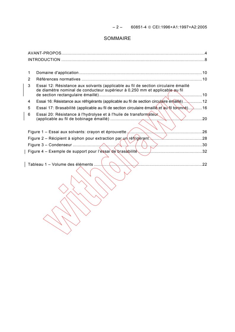
IEC 60851-4:1996+AMD1:1997+AMD2:2005 CSV - Winding wires - Test methods - Part 4: Chemical properties Released:3/29/2005
Overview
IEC 60851-4:1996 is an internationally recognized standard developed by the International Electrotechnical Commission (IEC) that specifies test methods for the chemical properties of winding wires used in electrical equipment. This standard forms part of the IEC 60851 series focused on insulated wires in windings and provides critical procedures for assessing chemical resistance and related properties to ensure the durability and reliability of winding wires.
This edition consolidates the base 1996 publication with amendments from 1997 and 2005, offering up-to-date guidance for manufacturers, engineers, and quality control professionals involved in electrical winding wire applications.
Key Topics
IEC 60851-4 outlines precise test methods covering essential chemical properties of winding wires:
Test 12: Resistance to solvents
Evaluates how enamelled winding wires resist various solvents, ensuring insulation integrity remains intact under exposure to chemical substances.Test 16: Resistance to refrigerants
Assesses enamelled round wires for stability and durability when in contact with refrigerants, which is crucial for wires used in refrigeration and air conditioning equipment.Test 17: Solderability
Defines the method for testing the ability of enamelled round wires and bunched wires to be soldered effectively, a key factor in electrical connection reliability.Test 20: Resistance to transformer oil and hydrolysis
Measures the wire’s capacity to withstand hydrolytic degradation and maintain performance when exposed to transformer oil, vital for wiring in transformer applications.
These chemical property tests guarantee that winding wires can operate safely and efficiently under environmental and operational chemical exposures.
Applications
IEC 60851-4 is specifically designed for assessing insulated wires used in various winding applications, including:
Electric motors and generators
Ensuring chemical resistance of winding wires enhances motor efficiency and longevity by preventing insulation breakdown.Transformers
Testing resistance to transformer oil and hydrolysis prevents premature failures in transformer windings.Refrigeration and air conditioning systems
Resistance to refrigerants ensures winding wires maintain insulation integrity under chemical exposure typical in cooling cycles.Electronic devices requiring soldered connections
Solderability tests confirm secure electrical joints and proper mechanical strength.
By adhering to these standardized test methods, manufacturers can certify that winding wires meet international quality benchmarks, reducing risks related to insulation damage and improving the reliability of electrical devices.
Related Standards
IEC 60851-4 complements other parts of the IEC 60851 series and related IEC standards:
- IEC 60851 (General test methods) – Provides overarching testing procedures for winding wires.
- IEC 60317 (Winding wire specifications) – Specifies dimensions, materials, and construction requirements for different types of winding wires.
- IEC 60264 (Packaging requirements) – Covers storage and handling conditions to maintain wire quality pre-installation.
Together, these standards form a comprehensive framework ensuring winding wires meet rigorous technical and chemical quality standards.
Keywords: IEC 60851-4, winding wires, chemical properties, resistance to solvents, resistance to refrigerants, solderability test, transformer oil resistance, electrical winding insulation, insulated wires, IEC standards for winding wires, electrical wire testing methods
Relations
- Effective Date
- 05-Sep-2023
- Effective Date
- 05-Sep-2023
- Effective Date
- 05-Sep-2023
Buy Documents
IEC 60851-4:1996+AMD1:1997 CSV - Winding wires - Test methods - Part 4: Chemical properties Released:11/26/1997
IEC 60851-4:1996+AMD1:1997+AMD2:2005 CSV - Winding wires - Test methods - Part 4: Chemical properties Released:3/29/2005
Get Certified
Connect with accredited certification bodies for this standard

IMQ S.p.A. (Certification)
Italian electrical product certification.

SLG Prüf- und Zertifizierungs GmbH
German testing and certification body.

UL Solutions
Global safety science company with testing, inspection and certification.
Sponsored listings
Frequently Asked Questions
IEC 60851-4:1996 is a standard published by the International Electrotechnical Commission (IEC). Its full title is "Methods of test for winding wires - Part 4: Chemical properties". This standard covers: Specifies the following tests: - Test 12: Resistance to solvents; - Test 16: Resistance to refrigerants; - Test 17: Solderability; - Test 20: Resistance to transformer oil
Specifies the following tests: - Test 12: Resistance to solvents; - Test 16: Resistance to refrigerants; - Test 17: Solderability; - Test 20: Resistance to transformer oil
IEC 60851-4:1996 is classified under the following ICS (International Classification for Standards) categories: 29.060.10 - Wires. The ICS classification helps identify the subject area and facilitates finding related standards.
IEC 60851-4:1996 has the following relationships with other standards: It is inter standard links to IEC 60851-4:1996/AMD2:2005, IEC 60851-4:1996/AMD1:1997, IEC 60851-4:2016. Understanding these relationships helps ensure you are using the most current and applicable version of the standard.
IEC 60851-4:1996 is available in PDF format for immediate download after purchase. The document can be added to your cart and obtained through the secure checkout process. Digital delivery ensures instant access to the complete standard document.
Standards Content (Sample)
NORME
CEI
INTERNATIONALE
IEC
60851-4
INTERNATIONAL
Edition 2.1
STANDARD
1997-11
Edition 2:1996 consolidée par l'amendement 1:1997
Edition 2:1996 consolidated with amendment 1:1997
Fils de bobinage – Méthodes d'essai –
Partie 4:
Propriétés chimiques
Winding wires – Test methods –
Part 4:
Chemical properties
Numéro de référence
Reference number
CEI/IEC 60851-4:1996 + A.1:1997
Numéros des publications Numbering
Depuis le 1er janvier 1997, les publications de la CEI As from the 1st January 1997 all IEC publications are
sont numérotées à partir de 60000. issued with a designation in the 60000 series.
Publications consolidées Consolidated publications
Les versions consolidées de certaines publications de Consolidated versions of some IEC publications
la CEI incorporant les amendements sont disponibles. including amendments are avai lable. For ex ample,
Par exemple, les numéros d’édition 1.0, 1.1 et 1.2 edition numbers 1.0, 1.1 and 1.2 refer, respectively, to
indiquent respectivement la publication de base, la the base publication, the base publication
publication de base incorporant l’amendement 1, et la incorporating amendment 1 and t he base publication
publication de base incorporant les amendements 1 incorporating amendments 1 and 2.
et 2.
Validité de la présente publication Validity of this publication
Le contenu technique des publications de la CEI est The technical content of IEC publications is kept under
constamment revu par l a CEI afin qu'il reflète l'état constant review by t he IEC, thus ensuring that the
actuel de la technique. content reflects current technology.
Des renseignements relatifs à l a date de Information relating to the date of the reconfirmation of
reconfirmation de la publication sont disponibles dans the publication is available in the IEC catalogue.
le Catalogue de la CEI.
Les renseignements relatifs à ces révisions, à l'établis- Information on the revision work, the issue of revised
sement des éditions révisées et aux amendements editions and amendments may be obt ained from
peuvent être obtenus auprès des Comités nationaux de IEC National Committees and from the following
la CEI et dans les documents ci-dessous: IEC sources:
• Bulletin de la CEI • IEC Bulletin
• Annuaire de la CEI • IEC Yearbook
Accès en ligne* On-line access*
• Catalogue des publications de la CEI • Catalogue of IEC publications
Publié annuellement et mis à jour régulièrement Published yearly with regular updates
(Accès en ligne)* (On-line access)*
Terminologie, symboles graphiques Terminology, graphical and letter
et littéraux symbols
En ce qui concerne la terminologie générale, le lecteur For general terminology, readers are ref erred to
se reportera à l a CEI 60050: Vocabulaire Electro- IEC 60050: International Electrotechnical Vocabulary
technique International (VEI). (IEV).
Pour les symboles graphiques, les symboles littéraux For graphical symbols, and letter symbols and signs
et les signes d'usage général approuvés par la CEI, le approved by t he IEC for general use, readers are
referred to publications IEC 60027: Letter symbols to
lecteur consultera la CEI 60027: Symboles littéraux à
utiliser en élec trotechnique, la CEI 60417: Symboles be used in electrical technology, IEC 60417: Graphical
graphiques utilisables sur le matériel. Index, relevé et symbols for use on equipment. Index, survey and
compilation of the single sheets
compilation des feuilles individuelles, et la CEI 60617: and IEC 60617:
Symboles graphiques pour schémas. Graphical symbols for diagrams.
Publications de la CEI établies par IEC publications prepared by the same
le même comité d'études technical committee
L'attention du lecteur est attirée sur les listes figurant The attention of readers is drawn to the end pages of
à la fin de c ette publication, qui énumèrent les this publication which list the IEC publications issued
publications de la CEI préparées par l e comité by the technical committee which has prepared t he
d'études qui a établi la présente publication. present publication.
* Voir adresse «site web» sur la page de titre. * See web site address on title page.
NORME
CEI
INTERNATIONALE
IEC
60851-4
INTERNATIONAL
Edition 2.1
STANDARD
1997-11
Edition 2:1996 consolidée par l'amendement 1:1997
Edition 2:1996 consolidated with amendment 1:1997
Fils de bobinage – Méthodes d'essai –
Partie 4:
Propriétés chimiques
Winding wires – Test methods –
Part 4:
Chemical properties
IEC 1997 Droits de reproduction réservés Copyright - all rights reserved
Aucune partie de cette publication ne peut être reproduite ni No part of this publication may be reproduced or ut ilized in
utilisée sous quelque forme que ce soi t et par aucun any form or by any means, electronic or mechanical,
procédé, électronique ou mécanique, y compris la photo- including photocopying and microfilm, without permission in
copie et les microfilms, sans l'accord écrit de l'éditeur. writing from the publisher.
International Electrotechnical Commission 3, rue de Varembé Geneva, Switzerland
Telefax: +41 22 919 0300 e-mail: inmail@iec.ch IEC web site http: //www.iec.ch
CODE PRIX
Commission Electrotechnique Internationale
PRICE CODE CD
International Electrotechnical Commission
Pour prix, voir catalogue en vigueur
For price, see current catalogue
– 2 – 60851-4 © CEI:1996 + A.1:1997
SOMMAIRE
Pages
AVANT-PROPOS . 4
INTRODUCTION . 6
Articles
1 Domaine d'application. 8
2 Références normatives. 8
3 Essai 12: Résistance aux solvants (applicable au fil de section circulaire émaillé
de diamètre nominal de conducteur supérieur à 0,250 mm et au fil de section
rectangulaire émaillé). 8
4 Essai 16: Résistance aux réfrigérants (applicable au fil de section circulaire émaillé). 10
5 Essai 17: Brasabilité (applicable au fil de section circulaire émaillé et au fil toronné). 14
6 Essai 20: Résistance à l'hydrolyse et à l'huile de transformateur
(applicable au fil de bobinage émaillé). 16
Figures. 24
60851-4 © IEC:1996 + A.1:1997 – 3 –
CONTENTS
Page
FOREWORD . 5
INTRODUCTION . 7
Clause
1 Scope.9
2 Normative references. 9
3 Test 12: Resistance to solvents (applicable to enamelled round wire with a nominal
conductor diameter over 0,250 mm and to enamelled rectangular wire) . 9
4 Test 16: Resistance to refrigerants (applicable to enamelled round wire) . 11
5 Test 17: Solderability (applicable to enamelled round wire and bunched wire) . 15
6 Test 20: Resistance to hydrolysis and to transformer oil
(applicable to enamelled wire) . 17
Figures. 25
– 4 – 60851-4 © CEI:1996 + A.1:1997
COMMISSION ÉLECTROTECHNIQUE INTERNATIONALE
__________
FILS DE BOBINAGE – MÉTHODES D'ESSAI –
Partie 4: Propriétés chimiques
AVANT-PROPOS
1) La CEI (Commission Electrotechnique Internationale) est une organisation mondiale de normalisation
composée de l'ensemble des comités électrotechniques nationaux (Comités nationaux de la CEI). La CEI a
pour objet de f avoriser la coopération internationale pour t outes les questions de normalisation dans les
domaines de l'électricité et de l'électronique. A cet effet, la CEI, entre autres activités, publie des Normes
internationales. Leur él aboration est confiée à des comités d'études, aux travaux desquels tout Comité
national intéressé par le sujet traité peut participer. Les organisations internationales, gouvernementales et
non gouvernementales, en liaison avec la CEI, participent également aux travaux. La CE I collabore
étroitement avec l'Organisation Internationale de Normalisation (ISO), selon des conditions fixées par accord
entre les deux organisations.
2) Les décisions ou ac cords officiels de l a CEI concernant des questions techniques, représentent, dans la
mesure du possible, un accord international sur les sujets étudiés, étant donné que les Comités nationaux
intéressés sont représentés dans chaque comité d'études.
3) Les documents produits se présentent sous la forme de recommandations internationales; ils sont publiés
comme normes, rapports techniques ou guides et agréés comme tels par les Comités nationaux.
4) Dans le but d'encourager l'unification internationale, les Comités nationaux de la CEI s'engagent à appliquer
de façon transparente, dans toute la mesure possible, les Normes internationales de la CEI dans leurs normes
nationales et régionales. Toute divergence entre la norme de l a CEI et la norme nationale ou régi onale
correspondante doit être indiquée en termes clairs dans cette dernière.
5) La CEI n'a fixé aucune procédure concernant le marquage comme indication d'approbation et sa responsabilité
n'est pas engagée quand un matériel est déclaré conforme à l'une de ses normes.
6) L'attention est attirée sur le fait que certains des éléments de la présente Norme internationale peuvent faire
l'objet de droi ts de propri été intellectuelle ou de droi ts analogues. La CEI ne saurait être tenue pour
responsable de ne pas avoir identifié de tels droits de propriété et de ne pas avoir signalé leur existence.
La Norme internationale CEI 60851-4 a été établie par le comité d'études 55 de la CEI: Fils de
bobinage.
Cette deuxième édition annule et remplace la première édition parue en 1985 et l'am endement 1
(1992), et constitue une révision technique.
La présente version consolidée de la CEI 60851- 4 est issue de la deuxième édition (1996)
[documents 55/473A/FDIS et 55/514/RVD] et de s on amendement 1 ( 1997) [documents
55/597/FDIS et 55/614/RVD].
Elle porte le numéro d'édition 2.1.
Une ligne ver ticale dans la m arge indique où la public ation de bas e a été modifiée par
l'amendement 1.
60851-4 © IEC:1996 + A.1:1997 – 5 –
INTERNATIONAL ELECTROTECHNICAL COMMISSION
__________
WINDING WIRES – TEST METHODS –
Part 4: Chemical properties
FOREWORD
1) The IEC (International Electrotechnical Commission) is a worldwide organization for standardization comprising
all national electrotechnical committees (IEC National Committees). The obj ect of the IEC is to promote
international cooperation on all questions concerning standardization in the electrical and electronic fields. To
this end and i n addition to other activities, the IEC publishes International Standards. Their preparation is
entrusted to technical committees; any I EC National Committee interested in the subject dealt with may
participate in this preparatory work. International, governmental and non-governmental organizations liaising
with the IEC also participate in this preparation. The I EC collaborates closely with the International
Organization for Standardization (ISO) in accordance with conditions determined by agreement between the
two organizations.
2) The formal decisions or agreem ents of the IEC on t echnical matters express, as nearly as possible an
international consensus of opinion on the relevant subjects since each technical committee has representation
from all interested National Committees.
3) The documents produced have the form of recommendations for international use and are publ ished in the
form of standards, technical reports or guides and they are accepted by the National Committees in that
sense.
4) In order to promote international unification, IEC National Committees undertake to apply IEC International
Standards transparently to the maximum extent possible in their national and regional standards. Any
divergence between the IEC Standard and the corresponding national or regional standard shall be clearly
indicated in the latter.
5) The IEC provides no marking procedure to indicate its approval and cannot be rendered res ponsible for any
equipment declared to be in conformity with one of its standards.
6) Attention is drawn to the possibility that some of the elements of this International Standard may be the subject
of patent rights. The IEC shall not be held responsible for identifying any or all such patent rights.
International Standard IEC 60851-4 has been pr epared by IEC technical committee 55:
Winding wires.
This second edition cancels and replaces the first edition published in 1985 and its amend-
ment 1 (1992), and constitutes a technical revision.
This consolidated version of IEC 60851- 4 is based on the s econd edition of IEC 60851-4
(1996) [documents 55/473A/FDIS and 55/514/RVD] and its amendment 1 (1997) [documents
55/597/FDIS and 55/614/RVD].
It bears the edition number 2.1.
A vertical line in the m argin shows where the bas e publication has been m odified by
amendment 1.
– 6 – 60851-4 © CEI:1996 + A.1:1997
INTRODUCTION
La présente partie de la CEI 60851 constitue un élément d'une série de normes traitant des fils
isolés utilisés dans les enroulements des appareils électriques. Cette s érie comporte trois
groupes définissant respectivement:
a) les méthodes d'essai (CEI 60851);
b) les spécifications (CEI 60317);
c) le conditionnement (CEI 60264).
60851-4 © IEC:1996 + A.1:1997 – 7 –
INTRODUCTION
This part of IEC 60851 forms an element of a series of standards which deals with insulated
wires used for windings in electrical equipment. The series has three groups describing:
a) methods of test (IEC 60851);
b) specifications (IEC 60317);
c) packaging (IEC 60264).
– 8 – 60851-4 © CEI:1996 + A.1:1997
FILS DE BOBINAGE – MÉTHODES D'ESSAI –
Partie 4: Propriétés chimiques
1 Domaine d'application
La présente partie de la CEI 60851 donne les méthodes d'essai suivantes:
– Essai 12: Résistance aux solvants;
– Essai 16: Résistance aux fluides réfrigérants;
– Essai 17: Brasabilité;
– Essai 20: Résistance à l'huile de transformateur.
Pour les définitions, les généralités concernant les méthodes d'essai et les séries complètes
des méthodes d'essai des fils de bobinage, voir la CEI 60851-1.
2 Références normatives
Les documents normatifs suivants contiennent des dispositions qui, par suite de la r éférence
qui y est faite, constituent des dispositions valables pour la présente partie de la CEI 60851.
Au moment de la publication, les éditions indiquées étaient en vigueur. Tout document normatif
est sujet à révision et les parties prenantes aux accords fondés sur la présente partie de
la CEI 60851 sont invitées à rechercher la possibilité d'appliquer les éditions les plus récentes
des documents normatifs indiqués ci-après. Les membres de la CEI et de l'ISO possèdent le
registre des Normes internationales en vigueur.
CEI 60296: 1982, Spécification des huiles minérales isolantes neuves pour transformateurs et
appareillage de connexion
CEI 60554-1: 1977, Spécification pour papiers cellulosiques à usages électriques – Première
partie: Définitions et conditions générales
CEI 60851-1: 1996, Fils de bobinage – Méthodes d'essai – Partie 1: Généralités
CEI 60851-3: 1996, Fils de bobinage – Méthodes d'essai – Partie 3: Propriétés mécaniques
CEI 60851-5: 1996, Fils de bobinage – Méthodes d'essai – Partie 5: Propriétés électriques
3 Essai 12: Résistance aux solvants (applicable au fil de section circulaire émaillé
de diamètre nominal de conducteur supérieur à 0,250 mm et au fil de section
rectangulaire émaillé)
La mesure de l'action du solvant sur l'émail n'est pas réalisable sur les fils jusqu'à et y compris
0,250 mm. L'essai ne sera appliqué que sur les fils supérieurs à 0,250 mm.
La résistance aux solvants est exprimée par la dureté-crayon du fil après l'action du solvant.
3.1 Equipement
Les solvants suivants doivent être utilisés:
– solvant normalisé comme spécifié ci-dessous, ou
– solvant agréé entre acheteur et fournisseur.
60851-4 © IEC:1996 + A.1:1997 – 9 –
WINDING WIRES – TEST METHODS –
Part 4: Chemical properties
1 Scope
This part of IEC 60851 specifies the following tests:
– Test 12: Resistance to solvents;
– Test 16: Resistance to refrigerants;
– Test 17: Solderability;
– Test 20: Resistance to transformer oil.
For definitions, general notes on methods of test and the complete series of methods of test for
winding wires see IEC 60851-1.
2 Normative references
The following normative documents contain provisions which, through reference in this text,
constitute provisions of this part of IEC 60851. At the time of publication, the editions indicated
were valid. All normative documents are subject to revision, and parties to agreements based
on this part of IEC 60851 are encouraged to investigate the possibility of applying the most
recent editions of the normative documents indicated below. Members of the IEC and ISO
maintain registers of currently valid International Standards.
IEC 60296: 1982, Specification for unused mineral insulating oils for transformers and
switchgear
IEC 60554-1: 1977, Specification for cellulosic papers for electrical purposes – Par t 1:
Definitions and general requirements
IEC 60851-1: 1996, Winding wires – Test methods – Part 1: General
IEC 60851-3: 1996, Winding wires – Test methods – Part 3: Mechanical properties
IEC 60851-5: 1996, Winding wires – Test methods – Part 5: Electrical properties
3 Test 12: Resistance to solvents (applicable to enamelled round wire with
a nominal conductor diameter over 0,250 mm and to enamelled rectangular wire)
The effect of solvent on enamel is not practicable for wires up to and including 0,250 mm. The
test should only be applicable to wires over 0,250 mm.
Resistance to solvents is expressed by the pencil hardness of the wire after solvent treatment.
3.1 Equipment
The following solvents shall be used:
– standard solvent as specified below, or
– solvent as agreed between purchaser and supplier.
– 10 – 60851-4 © CEI:1996 + A.1:1997
Le solvant normalisé doit être un mélange de:
– 60 % en volume de white spirit contenant un maximum de 18 % d'aromatique;
– 30 % en volume de xylène;
– 10 % en volume de butanol.
Le crayon utilisé doit avoir une mine de la dur eté spécifiée dans la norme appropriée. Avant
chaque essai, la pointe du crayon utilisé doit être affûtée avec une lime douce pour former un
angle de 60° symétriquement par rapport à l'axe de la mine conformément à la figure 1.
3.2 Procédure
Une longueur de fil droit de 150 mm environ doit être préconditionnée pendant 10 min à (130 ± 3) °C
dans une étuve à ventilation forcée. Une longueur substantielle du fil doit alors être immergée
dans le s olvant normalisé contenu dans un r écipient cylindrique en verre; elle doit y être
maintenue à (60 ± 3) °C pendant 30 min. Le fil doit alors être retiré du solvant. La dureté de la
surface du fil doit alors être mesurée comme indiqué ci-après. Le temps écoulé entre la sortie
du solvant et la mesure ne doit pas dépasser 30 s.
L'éprouvette à essayer doit être placée sur une surface lisse et dure conformément à la figure
1. Dans le cas de fils de section rectangulaire, l'essai doit être réalisé sur le côté plat du fil. La
mine de crayon doit être placée suivant un angle d'environ 60° sur la surface du fil et la pointe
affûtée du crayon doit être pressée lentement le long de la s urface du f il avec une f orce
d'environ 5 N.
Trois essais doivent être réalisés. On doit noter si le revêtement est enlevé et si le conducteur
nu est visible.
NOTE 1 – Cette méthode peut aussi être employée pour vérifier la résistance à d'autres fluides, par exemple l'huile.
NOTE 2 – Si on désire déterminer la dureté de l'isolant, l'indice de dureté de l'émail doit être pris égal à celui de la
mine de plus grande dureté avec laquelle on ne peut enlever l'émail, exprimé par la dureté-crayon. La série des
duretés-crayon est la suivante.
6B 5B 4B 3B 2B B HB H 2H 3H 4H 5H 6H 7H 8H 9H
____________________________________________________________________________________________
45 6789 10 11 12 13 14 15 16 17 18 19
4 Essai 16: Résistance aux réfrigérants (applicable au fil de section circulaire émaillé)
La résistance au réfrigérant 22 est exprimée par la quantité de matière extraite du revêtement
du fil et par la tension de claquage après exposition au réfrigérant.
NOTE 1 – Des fluides réfrigérants autres que le monochlorodifluorométhane (réfrigérant R 22) peuvent être utilisés.
Dans ce cas, on veillera aux données critiques de tels fluides, et les conditions de pres sion dans le réc ipient
satisferont aux autres conditions d'essai.
NOTE 2 – Des fluides réfrigérants comme le monochlorodifluorométhane et des fluides de rinçage comme le
trichlorotrifluoréthane (réfrigérant R 113) sont des produits chimiques réducteurs d'ozone (PRCO). Il sera donc
nécessaire de réviser cette méthode d'essai dès que des produits de substitution seront connus.
4.1 Extraction
4.1.1 Principe
Une coupe avec siphon contenant le fil est placée dans un récipient sous pression. La matière
extraite est déterminée après exposition du fil au réfrigérant sous pression à température élevée.
60851-4 © IEC:1996 + A.1:1997 – 11 –
The standard solvent shall be a mixture of:
– 60 % by volume white spirit with maximum aromatic content of 18 %;
– 30 % by volume xylene;
– 10 % by volume butanol.
The pencil to be used shall be a lead pencil of a hardness as specified in the relevant standard.
Before each test, the point of the pencil shall be sharpened with a smooth-cut file to form an
angle of 60° symmetrical about the axis of the lead according to figure 1.
3.2 Procedure
A straight piece of wire, approximately 150 mm in length, shall be preconditioned for 10 min at
(130 ± 3) °C in an oven with forced air circulation. A substantial length of the wire shall then be
immersed in standard solvent contained in a glass cylinder, and shall be maintained therein at
a temperature of (60 ± 3) °C for a period of 30 min. The wire shall then be removed from the
solvent. The hardness of the wire surface shall then be determined, in the following manner,
within a period of 30 s after removal from the solvent.
The specimen to be tested shall be laid on a smooth hard surface according to figure 1. In the
case of rectangular wires, the test shall be carried out on the f lat side of the wire. The pencil
shall be placed on the surface of the wire at an angle of approximately 60° and the sharpened
edge shall be pressed slowly along the surface of the wire with a force of approximately 5 N.
Three tests shall be made. It shall be reported, if the coating is removed with exposure of the
bare conductor.
NOTE 1 – This method can also be used for testing resistance to other fluids, for example oil.
NOTE 2 – Where it is desired to determine the hardness of the insulation, the hardness of the lead pencil which just
fails to remove the coating from the surface of the conductor shall be taken as the hardness of the wire surface,
expressed by the pencil hardness. The pencil hardness series is as follows:
6B 5B 4B 3B 2B B HB H 2H 3H 4H 5H 6H 7H 8H 9H
____________________________________________________________________________________________
45 6789 10 11 12 13 14 15 16 17 18 19
4 Test 16: Resistance to refrigerants (applicable to enamelled round wire)
Resistance to refrigerant 22 is expressed by the quantity of matter extracted from the coating
of the wire and by the breakdown voltage after exposure to a refrigerant.
NOTE 1 – Refrigerants other than monochlorodifluoromethane (refrigerant R 22) m ay be used. In this case, the
critical data of such fluid should be observed and the layout of the pressure vessel should comply with the test
altered conditions.
NOTE 2 – Refrigerants like monochlorodifluoromethane and rinsing fluids like trichlorotrifluorethane (refrigerant
R 113) are ozone depleting chemicals (ODC). Therefore, it will be necessary to revise this method of test as soon
as substitute materials are identified.
4.1 Extraction
4.1.1 Principle
A siphon cup containing the wire sample is placed in the pressure vessel. The extractable
matter is determined after exposure of the wire sample to the refrigerant under pressure and at
elevated temperature.
– 12 – 60851-4 © CEI:1996 + A.1:1997
4.1.2 Equipement
L'équipement suivant doit être utilisé:
– une coupe avec siphon conforme à la figure 2, d'une c apacité de 450 m l jusqu'au point de
siphonage;
– un récipient sous pression d'une capacité de 2 000 m l, d'un diamètre intérieur approximatif
de 100 mm permettant une pression d'utilisation de 200 bars (20 MPa), de construction non
soudée de préférence et équipé d'un système de chauffage régulé;
– le couvercle supérieur du récipient comprend un condenseur conforme à la figure 3;
– une étuve à ventilation forcée.
4.1.3 Eprouvette
Huit bobinages de 70 s pires doivent être réalisés avec des échantillons de fil avec chacun
(0,6 ± 0,1) g d'isolant. Les éprouvettes doivent être dégraissées et conditionnées en étuve à
ventilation forcée à (150 ± 3) °C pendant 15 m in. Après refroidissement de 30 m in, les huit
éprouvettes doivent être pesées ensemble à 0,0001 g près: cela constitue la masse initiale M .
4.1.4 Procédure
Les huit éprouvettes doivent être placées dans la coupe avec siphon qui est suspendue à (25 ± 5) mm
au-dessous du condenseur placé sous le couvercle du récipient sous pression. Le récipient de
pression doit être fermé et chargé de (700 ± 25) g de r éfrigérant 22. L'alimentation en eau et
l'écoulement du condenseur doivent être branchés et le récipient de pression doit être chauffé
entre 70 °C et 80 °C au m oyen d'un système de chauffage régulé. Le débit d'eau dans le
condenseur doit être ajusté de façon à réaliser de 20 à 25 s iphonages à l'heure de la c oupe
avec siphon. La durée de l'extraction doit être de 6 h.
La pression de vapeur du réfrigérant 22 pour la gamme de température spécifiée ci-dessus est
comprise entre 30 bars et 37 bars (3 MPa à 3,7 MPa). La pression critique du réfrigérant 22 est
de 50 bars (5 MPa). La pression du récipient ne doit pas dépasser 40 bars (4 MPa). Avant son
utilisation, on doit vérifier que la soupape de sécurité fonctionne correctement.
NOTE – Il est recommandé de couper automatiquement le chauffage si la pression dépasse 40 bars (4 MPa) ou si
le débit d'eau du condenseur s'interrompt.
A la fin du temps d'extraction, le récipient sous pression doit être refroidi à l'aide de neige
carbonique pour liquéfier le r éfrigérant; on doit alor s faire tomber la pr ession et
ouvrir le récipient. Les éprouvettes et la coupe avec siphon doivent êtr e rincées avec du
trichlorotrifluoréthane distillé (R 113 déshuilé) (voir la note 2 de c et article). Le produit de
rinçage doit être versé dans le récipient de pression. Le réfrigérant doit alors être évaporé
jusqu'à 5 mm environ du fond du récipient de pression. Les parois du récipient de pression
doivent être nettoyées à l'aide de deux rinçages successifs de 100 m l de c hlorure de
méthylène chacun et les solvants doivent être évaporés sous une hotte ou dans un espace
bien aéré jusqu'à 5 mm du fond du récipient de pression.
Le liquide doit êtr e transféré dans une capsule d'aluminium préalablement séchée et tarée
avec 15 ml de chlorure de méthylène de rinçage puis évaporé à sec à (150 ± 3) °C pendant 1 h.
La capsule doit être refroidie à la tem pérature ambiante dans un dessiccateur. La capsule
d'aluminium avec le résidu doit être pesée à 0,0001 g pr ès et la tar e de la c apsule est
soustraite. La différence est la masse de résidu totale M de matière extraite pour les huit
éprouvettes.
L'isolant des bobinages doit être retiré à l'aide d'un moyen chimique approprié qui n'affecte pas
le conducteur, les conducteurs nus doivent être séchés à (150 ± 3) °C pendant (15 ± 1) min et
refroidis à la tem pérature ambiante dans un dessiccateur. Les huit bobinages doivent être
pesés ensemble à 0,0001 g près, et leur masse est la masse totale du conducteur M .
60851-4 © IEC:1996 + A.1:1997 – 13 –
4.1.2 Equipment
The following equipment shall be used:
– siphon cup according to figure 2, of 450 ml volume up to the siphoning level;
– pressure vessel of 2 000 ml volume with an internal diameter of approximately 100 mm and
a pressure capacity of 200 bar (20 MPa), preferably of unwelded construction and provided
with a controlled heating system;
– top closure of the vessel containing a condenser coil according to figure 3;
– oven with forced air circulation.
4.1.3 Specimen
Eight wire samples each containing (0,6 ± 0,1) g of insulation shall be wound into coils of 70 turns.
The specimens shall be degreased and conditioned in an oven w ith forced air circulation at
(150 ± 3) °C for 15 min. After 30 min cooling, the eight specimens shall be weighed together to
the nearest 0,0001 g, resulting in the total initial mass M .
4.1.4 Procedure
The eight specimens shall be placed in the siphon cup, which is suspended (25 ± 5) mm below
the condenser coil on the pressure vessel cover. The pressure vessel shall be assembled and
charged with (700 ± 25) g of refrigerant 22. The condenser water supply and drain line shall be
connected and the pressure vessel shall be heated by means of a controlled heating system
with the temperature set between 70 °C and 80 °C. T he water flowing through the condenser
shall be adjusted to maintain a reflux rate of 20 to 25 discharges per hour from the siphon cup.
The extraction period shall be 6 h.
The vapour pressure of refrigerant 22 corresponding to the tem perature range as specified
above is 30 bar to 37 bar (3 MPa to 3,7 MPa) . The critical pressure of refrigerant 22 is 50 bar
(5 MPa). The pressure in the ves sel shall not exceed 40 bar (4 MPa). Therefore, prior to use
the over-pressure control valve shall be checked to ensure its proper functioning.
NOTE – I t is recommended that the heating system is automatically deactivated, if the pressure exceeds 40 bar
(4 MPa) or if the water flow through the condenser coil is interrupted.
At the end of the extraction period, the pressure vessel shall be cooled by means of solid
carbon dioxide to liquify the refrigerant, the pressure shall be released and the pressure vessel
opened. The specimens and siphon cup shall be rinsed with distilled trichlorotrifluor-ethane
(oil-free R 113) (see note 2 of this clause). The rinse shall be poured into the pressure vessel.
The refrigerant shall then be evaporated to approximately 5 mm of the bottom of the pressure
vessel. The walls of the pressure vessel shall be washed with two successive rinses each of
100 ml methylene chloride and the solvents shall then be evaporated under a hood or in a well-
ventilated area to approximately 5 mm from the bottom of the pressure vessel.
The liquid sample shall be transferred to a pr e-dried tared aluminium weighing dish with a 15 ml
methylene chloride rinse and then evaporated to dryness at (150 ± 3) °C for 1 h. The weighing
dish shall then be cooled to room temperature in a desiccator. The dish with the residue shall
be weighed to the near est 0,0001 g and the or iginal tared mass of the same dish subtracted.
The difference is the total residue mass M of the matter extracted from the eight specimens.
The insulation on the c oils shall be removed by suitable chemical means not affecting the
conductor, and the bare conductors shall be dried at (150 ± 3) °C for (15 ± 1) min and cooled to
room temperature in a desiccator. They shall be weighed to the nearest 0,0001 g and the mass
of the eight conductors together is the total conductor mass M .
– 14 – 60851-4 © CEI:1996 + A.1:1997
4.1.5 Résultats
La matière extraite doit être déterminée par l'équation suivante:
M
Matière extraite = × 100 %
MM−
Un essai doit être réalisé. On doit noter les masses M , M et M , la température et la pression
1 2 3
du récipient, ainsi que la matière extraite.
4.2 Tension de claquage
4.2.1 Principe
Une éprouvette préparée selon 4.4.1 de la CEI 60851-5 est placée dans le r écipient sous
pression selon les modalités de 4.2.2. La tension de claquage est déterminée après exposition
de l'éprouvette au réfrigérant sous pression et à température élevée.
4.2.2 Procédure
L'éprouvette doit être conditionnée en étuve à ( 150 ± 3) °C pendant 4 h puis placée dans le
récipient de pression qui doit être fermé et rempli de (1 400 ± 50) g de réfrigérant. Le récipient
sous pression doit être chauffé selon 4.1.4 de la présente norme, mais pendant (72 ± 1) h.
A la fin du temps d'exposition, le récipient sous pression doit être refroidi et vidé c omme décrit en
4.1.4. Lorsque la pression absolue à l'intérieur du tube est inférieure à 2 bars (0,2 MPa), le récipient
de pression doit être ouvert et l'éprouvette doit être transférée dans une étuve à ( 150 ± 3) °C
en un temps compris entre 25 s et 30 s. L'éprouvette doit être maintenue dans l'étuve pendant
(10 ± 1) min. Après avoir sorti l'éprouvette de l'étuve et l'avoir laissée refroidir à la température
ambiante, la tension de claquage doit être déterminée selon 4.4.1 de la CEI 60851-5.
4.2.3 Résultats
Cinq éprouvettes doivent être essayées. Les cinq valeurs individuelles doivent être notées.
5 Essai 17: Brasabilité (applicable au fil de section circulaire émaillé et au fil toronné)
La brasabilité est exprimée par le temps d'immersion nécessaire pour enlever le revêtement et
recouvrir de brasure le conducteur d'une éprouvette plongée dans un bain de brasure.
5.1 Equipement
L'équipement suivant doit être utilisé:
– un bain de br asure à tem pérature régulée d'un volum e suffisant pour en m aintenir la
température constante quand on immerge l'éprouvette à la tem pérature spécifiée dans la
norme appropriée. La composition de la br asure doit être d'un rapport de masse de 60
parties d'étain pour 40 parties de plomb;
– un porte-éprouvette qui laisse le fil libre sur au moins 20 mm entre les points d'appui quand
il est immergé dans la brasure. Le m atériel utilisé pour le porte-éprouvette ne doit pas
contaminer le bain de br asure et les dimensions du support ne doivent pas modifier
sensiblement la température du bain de brasure pendant l'immersion.
NOTE – Une contamination de la brasure par l'oxydation ou la présence de cuivre peut affecter le résultat.
60851-4 © IEC:1996 + A.1:1997 – 15 –
4.1.5 Result
The extractable matter shall be determined according to the following equation:
M
Extractable matter = × 100 %
MM−
One test shall be made. The masses M , M , M , the temperature and the pr essure of the
1 2 3
pressure vessel and the extractable matter shall be reported.
4.2 Breakdown voltage
4.2.1 Principle
A specimen prepared according to 4.4.1 of IEC 60851-5 is placed in a pr essure vessel
according to 4.2.2. The breakdown voltage is determined after exposure of the specimen to the
refrigerant under pressure and at elevated temperature.
4.2.2 Procedure
The specimen shall be conditioned in the oven ( 150 ± 3) °C for 4 h and then placed in the
pressure vessel, which shall be assembled and charged with (1 400 ± 50) g of refrigerant. The
pressure vessel shall be heated according to 4.1.4 of this standard but for a period of (72 ± 1) h.
At the end of the ex posure period, the pr essure vessel shall be cooled and discharged as
described under 4.1.4. When the pressure inside the tube is less than 2 bar (0,2 MPa) absolute,
the pressure vessel shall be opened and the specimen, within a period of 25 s to 30 s, transferred
to the oven at a temperature of (150 ± 3) °C. The specimen shall remain in the oven for (10 ± 1) min.
After the specimen is removed from the oven and allowed to cool to room temperature, the
breakdown voltage shall be determined according to 4.4.1 of IEC 60851-5.
4.2.3 Result
Five specimens shall be tested. The five single values shall be reported.
5 Test 17: Solderability (applicable to enamelled round wire and bunched wire)
Solderability is expressed by the time of immersion of the specimen in a solder bath required to
remove the coating and to coat the conductor with solder.
5.1 Equipment
The following equipment shall be used:
– temperature controlled solder bath of sufficient volume to maintain a constant solder
temperature when immersing the specimen at any temperature specified in the relevant
standard. Solder composition shall be of a mass ratio of 60 parts tin to 40 parts lead;
– any specimen holder that holds the wire under test free for at least 20 mm between the
points of support when immersed into the solder. The material used for the specimen holder
shall be such that the solder does not undergo any contamination and the dimensions of the
holder shall not lead to significant change of the bath temperature during immersion.
NOTE – Contamination of the solder due to oxidation or from copper may affect the results.
– 16 – 60851-4 © CEI:1996 + A.1:1997
5.2 Spécimen
5.2.1 Diamètre nominal du conducteur jusqu'à 0,050 mm inclus
Huit longueurs de fil droit doivent être torsadées ensemble sans tension excessive et doivent
être bobinées sur le porte-éprouvette.
5.2.2 Diamètre nominal du conducteur supérieur à 0,050 jusqu'à 0,100 mm inclus
Une longueur de fil droit doit être bobinée sur le porte-éprouvette.
5.2.3 Diamètre nominal du conducteur supérieur à 0,100 mm
Une longueur de fil droit de 200 mm est nécessaire.
5.2.4 Fil toronné de diamètre extérieur jusqu'à 0,250 mm inclus
Une longueur de fil toronné doit être bobiné sur une distance de 15 mm à 20 mm à l'extrémité
d'un fil droit de cuivre étamé propre de diamètre nominal du conducteur de 0,800 mm et de 200 mm
de long. Il doit y avoir entre cinq et dix spires légèrement espacées.
5.2.5 Fil toronné de diamètre extérieur supérieur à 0,250 mm
Une longueur de fil toronné droit de 200 mm approximativement est nécessaire.
5.3 Procédure
L'éprouvette doit être tenue verticalement au-dessus du c entre du bain m aintenu à la
température spécifiée dans la norme appropriée. L'extrémité inférieure doit être abaissée à 20 mm
au-dessous de la s urface. La position à laquelle l'épr ouvette est immergée doit être à une
distance d'environ 10 mm du point où la tem pérature est mesurée. Après avoir été immergée
pendant le temps donné dans la feuille de spécification appropriée, l'éprouvette doit subir un
mouvement latéral dans le bain avant d'être retirée de la brasure.
On doit examiner la surface du fil étamé avec un grossissement de six à dix fois. Dans le cas
de fil de diamètre nominal du conducteur jusqu'à 0,100 mm inclus, l'examen doit être limité à la
partie libre de l'éprouvette.
Trois éprouvettes doivent être essayées. On doit noter l'état de surface du fil.
6 Essai 20: Résistance à l'hydrolyse et à l'huile de transformateur
(applicable au fil de bobinage émaillé)
La résistance à l’hydrolyse est exprimée par l’aspect et l’adhérence des éprouvettes après
exposition à l’huile de tr ansformateur en pr ésence d’eau s ous pression et à température
élevée.
La résistance à l'huile de tr ansformateur est exprimée par la tension de claquage et la
souplesse des éprouvettes après exposition à l'huile de transformateur sous pression et à
température élevée.
NOTE – L'eau peut affecter le revêtement par dégradation hydrolytique et/ou par absorption. Si l'absorption seule
apparaît, un séchage de l 'éprouvette à 125 ° C ± 3 ° C pendant 30 m in avant l'essai de t ension de c laquage
permettra à l'éprouvette de retrouver ses performances. Un fil de diamètre nominal du conducteur compris entre
0,800 mm et 1,500 mm a généralement été jugé convenable pour les manipulations et pour l'essai.
60851-4 © IEC:1996 + A.1:1997 – 17 –
5.2 Specimen
5.2.1 Nominal conductor diameter up to and including 0,050 mm
Eight straight pieces of wires shall be twisted together without undue tension and shall be
wound on the specimen holder.
5.2.2 Nominal conductor diameter over 0,050 mm up to and including 0,100 mm
A straight piece of wire shall be wound on a specimen holder.
5.2.3 Nominal conductor diameter over 0,100 mm
A straight piece of wire 200 mm in length is required.
5.2.4 Bunched wire with overall diameter up to and including 0,250 mm
A piece of bunched wire shall be wound for a distance of 15 mm to 20 mm around the end of a
straight piece of clean tinned copper wire of a nominal conductor diameter of 0,800 mm and
200 mm in length. T here shall be a m inimum of five turns and a m aximum of ten turns with a
slight spacing between the turns.
5.2.5 Bunched wire with overall diameter over 0,250 mm
A straight piece of bunched wire approximately 200 mm in length is required.
5.3 Procedure
The specimen shall be held vertically over the centre of the bath maintained at the temperature
as specified in the relevant standard. The bottom end shall be lowered to 20 mm below the
surface of the bath. The position at which the specimen is immersed shall be within 10 mm of
the point where the temperature is measured. After immersion for the time specified in the
relevant specification sheet, the specimen shall be moved sideways in the bath bef ore it is
withdrawn from the solder.
The surface of the tinned wire shall be examined with a magnification of from six to ten times.
In the case of wire up to and including 0,100 mm nominal conductor diameter, the examination
shall be restricted to the free length of the specimen.
Three specimens shall be tested. The condition of the surface of the wire shall be reported.
6 Test 20: Resistance to hydrolysis and to transformer oil
(applicable to enamelled wire)
Resistance to hydrolysis is expressed by appearance and adherence after exposure of the
specimens to tr ansformer oil in the pr esence of water under pressure and at elevated
temperature.
Resistance to transformer oil is expressed by breakdown voltage and flexibility after exposure
of the specimens to transformer oil under pressure and at elevated temperature.
NOTE – The water may affect the coating by hydrolytic degradation and/or by absorption. If only absorption has
occurred, drying the specimen at 125 °C ± 3 °C for 30 m in prior to the breakdown voltage test will produce a
recovery of the specimen. Wire with a nominal conductor diameter between 0,800 mm and 1,500 mm has been
generally found convenient to handle and to test.
– 18 – 60851-4 © CEI:1996 + A.1:1997
6.1 Fil de section circulaire
6.1.1 Equipement
L'équipement suivant est utilisé:
– deux tubes en verre de diamètre 25 mm et de longueur 300 mm qui peuvent être scellés;
– un récipient en acier inoxydable de volume 400 ml à 500 ml, pouvant supporter une pression
de 6 × 10 Pa, de préférence sans soudure et équipé d'une régulation de chauffage;
– de l'huile de transformateur conforme à la CEI 60296;
– du papier conforme à la CEI 60554-1, type 1.
6.1.2 Eprouvettes
Les éprouvettes suivantes sont préparées:
– 12 longueurs droites de fil d'environ 200 mm de long;
– 10 éprouvettes torsadées préparées conformément à 4.4.1 de la CEI 60851-5;
– trois éprouvettes enroulées sur mandrin préparées conformément à 5.1.1 de la CEI 60851-3.
6.1.3 Procédure
6.1.3.1 Résistance à l'hydrolyse
Chacun des tubes est chargé avec six longueurs droites de fil conformes à 6.1.2 et avec 80 ml
d'huile de transformateur
...
NORME CEI
INTERNATIONALE IEC
60851-4
INTERNATIONAL
Edition 2.2
STANDARD
2005-03
Edition 2:1996 consolidée par les amendements 1:1997 et 2:2005
Edition 2:1996 consolidated with amendments 1:1997 and 2:2005
Fils de bobinage – Méthodes d'essai –
Partie 4:
Propriétés chimiques
Winding wires – Test methods –
Part 4:
Chemical properties
Numéro de référence
Reference number
CEI/IEC 60851-4:1996+A1:1997+A2:2005
Numérotation des publications Publication numbering
Depuis le 1er janvier 1997, les publications de la CEI As from 1 January 1997 all IEC publications are
sont numérotées à partir de 60000. Ainsi, la CEI 34-1 issued with a designation in the 60000 series. For
devient la CEI 60034-1. example, IEC 34-1 is now referred to as IEC 60034-1.
Editions consolidées Consolidated editions
Les versions consolidées de certaines publications de la The IEC is now publishing consolidated versions of its
CEI incorporant les amendements sont disponibles. Par publications. For example, edition numbers 1.0, 1.1
exemple, les numéros d’édition 1.0, 1.1 et 1.2 indiquent and 1.2 refer, respectively, to the base publication,
respectivement la publication de base, la publication de the base publication incorporating amendment 1 and
base incorporant l’amendement 1, et la publication de the base publication incorporating amendments 1
base incorporant les amendements 1 et 2. and 2.
Informations supplémentaires Further information on IEC publications
sur les publications de la CEI
Le contenu technique des publications de la CEI est The technical content of IEC publications is kept
constamment revu par la CEI afin qu'il reflète l'état under constant review by the IEC, thus ensuring that
actuel de la technique. Des renseignements relatifs à the content reflects current technology. Information
cette publication, y compris sa validité, sont dispo- relating to this publication, including its validity, is
nibles dans le Catalogue des publications de la CEI available in the IEC Catalogue of publications
(voir ci-dessous) en plus des nouvelles éditions, (see below) in addition to new editions, amendments
amendements et corrigenda. Des informations sur les and corrigenda. Information on the subjects under
sujets à l’étude et l’avancement des travaux entrepris consideration and work in progress undertaken by the
par le comité d’études qui a élaboré cette publication, technical committee which has prepared this
ainsi que la liste des publications parues, sont publication, as well as the list of publications issued,
également disponibles par l’intermédiaire de: is also available from the following:
• Site web de la CEI (www.iec.ch) • IEC Web Site (www.iec.ch)
• Catalogue des publications de la CEI • Catalogue of IEC publications
Le catalogue en ligne sur le site web de la CEI The on-line catalogue on the IEC web site
(www.iec.ch/searchpub) vous permet de faire des (www.iec.ch/searchpub) enables you to search by a
recherches en utilisant de nombreux critères, variety of criteria including text searches,
comprenant des recherches textuelles, par comité technical committees and date of publication. On-
d’études ou date de publication. Des informations en line information is also available on recently
ligne sont également disponibles sur les nouvelles issued publications, withdrawn and replaced
publications, les publications remplacées ou retirées, publications, as well as corrigenda.
ainsi que sur les corrigenda.
• IEC Just Published • IEC Just Published
Ce résumé des dernières publications parues This summary of recently issued publications
(www.iec.ch/online_news/justpub) est aussi dispo- (www.iec.ch/online_news/justpub) is also available
nible par courrier électronique. Veuillez prendre by email. Please contact the Customer Service
contact avec le Service client (voir ci-dessous) Centre (see below) for further information.
pour plus d’informations.
• Service clients • Customer Service Centre
Si vous avez des questions au sujet de cette If you have any questions regarding this
publication ou avez besoin de renseignements publication or need further assistance, please
supplémentaires, prenez contact avec le Service contact the Customer Service Centre:
clients:
Email: custserv@iec.ch Email: custserv@iec.ch
Tél: +41 22 919 02 11 Tel: +41 22 919 02 11
Fax: +41 22 919 03 00 Fax: +41 22 919 03 00
.
NORME CEI
INTERNATIONALE IEC
60851-4
INTERNATIONAL
Edition 2.2
STANDARD
2005-03
Edition 2:1996 consolidée par les amendements 1:1997 et 2:2005
Edition 2:1996 consolidated with amendments 1:1997 and 2:2005
Fils de bobinage – Méthodes d'essai –
Partie 4:
Propriétés chimiques
Winding wires – Test methods –
Part 4:
Chemical properties
IEC 2005 Droits de reproduction réservés Copyright - all rights reserved
Aucune partie de cette publication ne peut être reproduite ni No part of this publication may be reproduced or utilized in any
utilisée sous quelque forme que ce soit et par aucun procédé, form or by any means, electronic or mechanical, including
électronique ou mécanique, y compris la photocopie et les photocopying and microfilm, without permission in writing from
microfilms, sans l'accord écrit de l'éditeur. the publisher.
International Electrotechnical Commission, 3, rue de Varembé, PO Box 131, CH-1211 Geneva 20, Switzerland
Telephone: +41 22 919 02 11 Telefax: +41 22 919 03 00 E-mail: inmail@iec.ch Web: www.iec.ch
CODE PRIX
CG
Commission Electrotechnique Internationale
PRICE CODE
International Electrotechnical Commission
Международная Электротехническая Комиссия
Pour prix, voir catalogue en vigueur
For price, see current catalogue
– 2 – 60851-4 CEI:1996+A1:1997+A2:2005
SOMMAIRE
AVANT-PROPOS.4
INTRODUCTION .8
1 Domaine d'application.10
2 Références normatives .10
3 Essai 12: Résistance aux solvants (applicable au fil de section circulaire émaillé
de diamètre nominal de conducteur supérieur à 0,250 mm et applicable au fil
de section rectangulaire émaillé).10
4 Essai 16: Résistance aux réfrigérants (applicable au fil de section circulaire émaillé).12
5 Essai 17: Brasabilité (applicable au fil de section circulaire émaillé et au fil toronné).16
6 Essai 20: Résistance à l'hydrolyse et à l'huile de transformateur
(applicable au fil de bobinage émaillé) .20
Figure 1 – Essai aux solvants: crayon et éprouvette.26
Figure 2 – Récipient à siphon pour extraction par un réfrigérant .28
Figure 3 – Condenseur .30
Figure 4 – Exemple de support pour l’essai de brasabilité .32
Tableau 1 – Volume des éléments .22
60851-4 © IEC:1996+A1:1997+A2:2005 – 3 –
CONTENTS
FOREWORD .5
INTRODUCTION .9
1 Scope .11
2 Normative references.11
3 Test 12: Resistance to solvents (applicable to enamelled round wire
with a nominal conductor diameter over 0,250 mm and applicable
to enamelled rectangular wire).11
4 Test 16: Resistance to refrigerants (applicable to enamelled round wire) .13
5 Test 17: Solderability (applicable to enamelled round wire and bunched wire).17
6 Test 20: Resistance to hydrolysis and to transformer oil
(applicable to enamelled wire) .21
Figure 1 – Pencil and specimen for solvent test.27
Figure 2 – Refrigerant extractable test siphon cup.29
Figure 3 – Condenser coils .31
Figure 4 – Example of carrier for solderability test.33
Table 1 – Volume of components .23
– 4 – 60851-4 © CEI:1996+A1:1997+A2:2005
COMMISSION ÉLECTROTECHNIQUE INTERNATIONALE
____________
FILS DE BOBINAGE – MÉTHODES D'ESSAI –
Partie 4: Propriétés chimiques
AVANT-PROPOS
1) La Commission Electrotechnique Internationale (CEI) est une organisation mondiale de normalisation composée
de l'ensemble des comités électrotechniques nationaux (Comités nationaux de la CEI). La CEI a pour objet de
favoriser la coopération internationale pour toutes les questions de normalisation dans les domaines de
l'électricité et de l'électronique. A cet effet, la CEI – entre autres activités – publie des Normes internationales,
des Spécifications techniques, des Rapports techniques, des Spécifications accessibles au public (PAS) et des
Guides (ci-après dénommés "Publication(s) de la CEI"). Leur élaboration est confiée à des comités d'études,
aux travaux desquels tout Comité national intéressé par le sujet traité peut participer. Les organisations
internationales, gouvernementales et non gouvernementales, en liaison avec la CEI, participent également aux
travaux. La CEI collabore étroitement avec l'Organisation Internationale de Normalisation (ISO), selon des
conditions fixées par accord entre les deux organisations.
2) Les décisions ou accords officiels de la CEI concernant les questions techniques représentent, dans la mesure
du possible, un accord international sur les sujets étudiés, étant donné que les Comités nationaux de la CEI
intéressés sont représentés dans chaque comité d’études.
3) Les Publications de la CEI se présentent sous la forme de recommandations internationales et sont agréées
comme telles par les Comités nationaux de la CEI. Tous les efforts raisonnables sont entrepris afin que la CEI
s'assure de l'exactitude du contenu technique de ses publications; la CEI ne peut pas être tenue responsable de
l'éventuelle mauvaise utilisation ou interprétation qui en est faite par un quelconque utilisateur final.
4) Dans le but d'encourager l'uniformité internationale, les Comités nationaux de la CEI s'engagent, dans toute la
mesure possible, à appliquer de façon transparente les Publications de la CEI dans leurs publications
nationales et régionales. Toutes divergences entre toutes Publications de la CEI et toutes publications
nationales ou régionales correspondantes doivent être indiquées en termes clairs dans ces dernières.
5) La CEI n’a prévu aucune procédure de marquage valant indication d’approbation et n'engage pas sa
responsabilité pour les équipements déclarés conformes à une de ses Publications.
6) Tous les utilisateurs doivent s'assurer qu'ils sont en possession de la dernière édition de cette publication.
7) Aucune responsabilité ne doit être imputée à la CEI, à ses administrateurs, employés, auxiliaires ou
mandataires, y compris ses experts particuliers et les membres de ses comités d'études et des Comités
nationaux de la CEI, pour tout préjudice causé en cas de dommages corporels et matériels, ou de tout autre
dommage de quelque nature que ce soit, directe ou indirecte, ou pour supporter les coûts (y compris les frais
de justice) et les dépenses découlant de la publication ou de l'utilisation de cette Publication de la CEI ou de
toute autre Publication de la CEI, ou au crédit qui lui est accordé.
8) L'attention est attirée sur les références normatives citées dans cette publication. L'utilisation de publications
référencées est obligatoire pour une application correcte de la présente publication.
9) L’attention est attirée sur le fait que certains des éléments de la présente Publication de la CEI peuvent faire
l’objet de droits de propriété intellectuelle ou de droits analogues. La CEI ne saurait être tenue pour
responsable de ne pas avoir identifié de tels droits de propriété et de ne pas avoir signalé leur existence.
La Norme internationale CEI 60851-4 a été établie par le comité d'études 55 de la CEI: Fils de
bobinage.
La présente version consolidée de la CEI 60851-4 comprend la deuxième édition (1996)
[documents 55/473A/FDIS et 55/514/RVD], son amendement 1 (1997) [documents
55/597/FDIS et 55/614/RVD] et son amendement 2 (2005) [documents 55/924/FDIS et
55/937/RVD].
Le contenu technique de cette version consolidée est donc identique à celui de l'édition de
base et à ses amendements; cette version a été préparée par commodité pour l'utilisateur.
Elle porte le numéro d'édition 2.2.
Une ligne verticale dans la marge indique où la publication de base a été modifiée par les
amendements 1 et 2.
60851-4 © IEC:1996+A1:1997+A2:2005 – 5 –
INTERNATIONAL ELECTROTECHNICAL COMMISSION
____________
WINDING WIRES – TEST METHODS –
Part 4: Chemical properties
FOREWORD
1) The International Electrotechnical Commission (IEC) is a worldwide organization for standardization comprising
all national electrotechnical committees (IEC National Committees). The object of IEC is to promote
international co-operation on all questions concerning standardization in the electrical and electronic fields. To
this end and in addition to other activities, IEC publishes International Standards, Technical Specifications,
Technical Reports, Publicly Available Specifications (PAS) and Guides (hereafter referred to as “IEC
Publication(s)”). Their preparation is entrusted to technical committees; any IEC National Committee interested
in the subject dealt with may participate in this preparatory work. International, governmental and non-
governmental organizations liaising with the IEC also participate in this preparation. IEC collaborates closely
with the International Organization for Standardization (ISO) in accordance with conditions determined by
agreement between the two organizations.
2) The formal decisions or agreements of IEC on technical matters express, as nearly as possible, an international
consensus of opinion on the relevant subjects since each technical committee has representation from all
interested IEC National Committees.
3) IEC Publications have the form of recommendations for international use and are accepted by IEC National
Committees in that sense. While all reasonable efforts are made to ensure that the technical content of IEC
Publications is accurate, IEC cannot be held responsible for the way in which they are used or for any
misinterpretation by any end user.
4) In order to promote international uniformity, IEC National Committees undertake to apply IEC Publications
transparently to the maximum extent possible in their national and regional publications. Any divergence
between any IEC Publication and the corresponding national or regional publication shall be clearly indicated in
the latter.
5) IEC provides no marking procedure to indicate its approval and cannot be rendered responsible for any
equipment declared to be in conformity with an IEC Publication.
6) All users should ensure that they have the latest edition of this publication.
7) No liability shall attach to IEC or its directors, employees, servants or agents including individual experts and
members of its technical committees and IEC National Committees for any personal injury, property damage or
other damage of any nature whatsoever, whether direct or indirect, or for costs (including legal fees) and
expenses arising out of the publication, use of, or reliance upon, this IEC Publication or any other IEC
Publications.
8) Attention is drawn to the Normative references cited in this publication. Use of the referenced publications is
indispensable for the correct application of this publication.
9) Attention is drawn to the possibility that some of the elements of this IEC Publication may be the subject of
patent rights. IEC shall not be held responsible for identifying any or all such patent rights.
International Standard IEC 60851-4 has been prepared by IEC technical committee 55:
Winding wires.
This consolidated version of IEC 60851-4 consists of the second edition of IEC 60851-4 (1996)
[documents 55/473A/FDIS and 55/514/RVD], its amendment 1 (1997) [documents 55/597/FDIS
and 55/614/RVD] and its amendment 2 (2005) [documents 55/924/FDIS and 55/937/RVD].
The technical content is therefore identical to the base edition and its amendments and has
been prepared for user convenience.
It bears the edition number 2.2.
A vertical line in the margin shows where the base publication has been modified by
amendments 1 and 2.
– 6 – 60851-4 CEI:1996+A1:1997+A2:2005
Le comité a décidé que le contenu de la publication de base et de ses amendements ne sera
pas modifié avant la date de maintenance indiquée sur le site web de la CEI sous
"http://webstore.iec.ch" dans les données relatives à la publication recherchée. A cette date,
la publication sera
• reconduite,
• supprimée,
• remplacée par une édition révisée, ou
• amendée.
60851-4 © IEC:1996+A1:1997+A2:2005 – 7 –
The committee has decided that the contents of the base publication and its amendments will
remain unchanged until the maintenance result date indicated on the IEC web site under
"http://webstore.iec.ch" in the data related to the specific publication. At this date,
the publication will be
• reconfirmed,
• withdrawn,
• replaced by a revised edition, or
• amended.
– 8 – 60851-4 CEI:1996+A1:1997+A2:2005
INTRODUCTION
La présente partie de la CEI 60851 constitue un élément d'une série de normes traitant des
fils isolés utilisés dans les enroulements des appareils électriques. Cette série comporte trois
groupes définissant respectivement:
a) les méthodes d'essai (CEI 60851);
b) les spécifications (CEI 60317);
c) le conditionnement (CEI 60264).
60851-4 © IEC:1996+A1:1997+A2:2005 – 9 –
INTRODUCTION
This part of IEC 60851 forms an element of a series of standards which deals with insulated
wires used for windings in electrical equipment. The series has three groups describing:
a) methods of test (IEC 60851);
b) specifications (IEC 60317);
c) packaging (IEC 60264).
– 10 – 60851-4 CEI:1996+A1:1997+A2:2005
FILS DE BOBINAGE – MÉTHODES D'ESSAI –
Partie 4: Propriétés chimiques
1 Domaine d'application
La présente partie de la CEI 60851 donne les méthodes d'essai suivantes:
– Essai 12: Résistance aux solvants;
– Essai 16: Résistance aux fluides réfrigérants;
– Essai 17: Brasabilité;
– Essai 20: Résistance à l'huile de transformateur.
Pour les définitions, les généralités concernant les méthodes d'essai et les séries complètes
des méthodes d'essai des fils de bobinage, voir la CEI 60851-1.
2 Références normatives
Les documents de référence suivants sont indispensables pour l'application du présent
document. Pour les références datées, seule l'édition citée s'applique. Pour les références
non datées, la dernière édition du document de référence s'applique (y compris les éventuels
amendements).
CEI 60296:1982, Spécification des huiles minérales isolantes neuves pour transformateurs et
appareillage de connexion
CEI 60554-1:1977, Spécification pour papiers cellulosiques à usages électriques – Première
partie: Définitions et conditions générales
CEI 60851-1:1996, Fils de bobinage – Méthodes d'essai – Partie 1: Généralités
CEI 60851-3:1996, Fils de bobinage – Méthodes d'essai – Partie 3: Propriétés mécaniques
CEI 60851-5:1996, Fils de bobinage – Méthodes d'essai – Partie 5: Propriétés électriques
3 Essai 12: Résistance aux solvants (applicable au fil de section circulaire émaillé
de diamètre nominal de conducteur supérieur à 0,250 mm et applicable au fil de
section rectangulaire émaillé)
L’essai n’est pas adapté aux fils de section circulaire de diamètre nominal de conducteur
jusqu’à 0,250 mm inclus.
La résistance aux solvants est exprimée par la dureté-crayon du fil après l'action du solvant.
3.1 Equipement
Les solvants suivants doivent être utilisés:
– solvant normalisé comme spécifié ci-dessous, ou
– solvant agréé entre acheteur et fournisseur.
60851-4 © IEC:1996+A1:1997+A2:2005 – 11 –
WINDING WIRES – TEST METHODS –
Part 4: Chemical properties
1 Scope
This part of IEC 60851 specifies the following tests:
– Test 12: Resistance to solvents;
– Test 16: Resistance to refrigerants;
– Test 17: Solderability;
– Test 20: Resistance to transformer oil.
For definitions, general notes on methods of test and the complete series of methods of test
for winding wires see IEC 60851-1.
2 Normative references
The following referenced documents are indispensable for the application of this document.
For dated references, only the edition cited applies. For undated references, the latest edition
of the referenced document (including any amendments) applies.
IEC 60296:1982, Specification for unused mineral insulating oils for transformers and
switchgear
IEC 60554-1:1977, Specification for cellulosic papers for electrical purposes – Part 1:
Definitions and general requirements
IEC 60851-1:1996, Winding wires – Test methods – Part 1: General
IEC 60851-3:1996, Winding wires – Test methods – Part 3: Mechanical properties
IEC 60851-5:1996, Winding wires – Test methods – Part 5: Electrical properties
3 Test 12: Resistance to solvents (applicable to enamelled round wire
with a nominal conductor diameter over 0,250 mm and applicable
to enamelled rectangular wire)
The test is not suitable for round wires with a nominal conductor diameter up to and including
0,250 mm.
Resistance to solvents is expressed by the pencil hardness of the wire after solvent
treatment.
3.1 Equipment
The following solvents shall be used:
– standard solvent as specified below, or
– solvent as agreed between purchaser and supplier.
– 12 – 60851-4 CEI:1996+A1:1997+A2:2005
Le solvant normalisé doit être un mélange de:
– 60 % en volume de white spirit contenant un maximum de 18 % d'aromatique;
– 30 % en volume de xylène;
– 10 % en volume de butanol.
Le crayon utilisé doit avoir une mine de la dureté spécifiée dans la norme appropriée. Avant
chaque essai, la pointe du crayon utilisé doit être affûtée avec une lime douce pour former un
angle de 60° symétriquement par rapport à l'axe de la mine conformément à la Figure 1.
3.2 Procédure
Une longueur de fil droit de 150 mm environ doit être préconditionnée pendant (10 ± 1) min à
(130 ± 3) °C dans une étuve à ventilation forcée. Une longueur substantielle du fil doit alors
être immergée dans le solvant normalisé contenu dans un récipient cylindrique en verre; elle
doit y être maintenue à (60 ± 3) °C pendant (30 ± 3) min. Le fil doit alors être retiré du
solvant. La dureté de la surface du fil doit alors être mesurée comme indiqué ci-après. Le
temps écoulé entre la sortie du solvant et la mesure ne doit pas dépasser 30 s.
L'éprouvette à essayer doit être placée sur une surface lisse et dure conformément à la
Figure 1. Dans le cas de fils de section rectangulaire, l'essai doit être réalisé sur le côté le
plus grand du fil. La mine de crayon doit être placée suivant un angle d'environ (60 ± 5)° sur
la surface du fil et la pointe affûtée du crayon doit être pressée lentement le long de la
surface du fil avec une force d'environ (5 ± 0,5) N.
Trois essais doivent être réalisés. On doit noter si le revêtement est enlevé et si le
conducteur nu est visible.
NOTE 1 Cette méthode peut aussi être employée pour vérifier la résistance à d'autres fluides, par exemple
l'huile.
NOTE 2 Si on désire déterminer la dureté de l'isolant, l'indice de dureté de l'émail doit être pris égal à celui de la
mine de plus grande dureté avec laquelle on ne peut enlever l'émail, exprimé par la dureté-crayon. La série des
duretés-crayon est la suivante.
6B 5B 4B 3B 2B B HB H 2H 3H 4H 5H 6H 7H 8H 9H
____________________________________________________________________________________________
4 5 6 7 8 9 10 11 12 13 14 15 16 17 18 19
4 Essai 16: Résistance aux réfrigérants (applicable au fil de section circulaire émaillé)
La résistance au réfrigérant est exprimée par la quantité de matière extraite du revêtement
du fil et par la tension de claquage après exposition au réfrigérant.
NOTE 1 Les données de cette méthode d’essai s’appliquent au monochlorodifluorométhane (réfrigérant R 22).
D’autres réfrigérants peuvent être utilisés, auquel cas il est recommandé de veiller aux données critiques de tels
fluides, et il convient que le fonctionnement du récipient sous pression satisfasse aux conditions d'essai révisées.
NOTE 2 Des fluides réfrigérants comme le monochlorodifluorométhane et des fluides de rinçage comme le
trichlorotrifluoréthane (réfrigérant R 113) sont des produits chimiques réducteurs de la couche d'ozone (PRCO). Il
convient que le réfrigérant et le fluide de rinçage fassent l’objet d’un accord entre le client et le fournisseur.
4.1 Extraction
4.1.1 Principe
Une coupe avec siphon contenant le fil est placée dans un récipient sous pression. La
matière extraite est déterminée après exposition du fil au réfrigérant sous pression à température
élevée.
60851-4 © IEC:1996+A1:1997+A2:2005 – 13 –
The standard solvent shall be a mixture of:
– 60 % by volume white spirit with maximum aromatic content of 18 %;
– 30 % by volume xylene;
– 10 % by volume butanol.
The pencil to be used shall be a lead pencil of a hardness as specified in the relevant
standard. Before each test, the point of the pencil shall be sharpened with a smooth-cut file
to form an angle of 60° symmetrical about the axis of the lead according to Figure 1.
3.2 Procedure
A straight piece of wire, approximately 150 mm in length, shall be preconditioned for
(10 ± 1) min at (130 ± 3) °C in an oven with forced air circulation. A substantial length of the
wire shall then be immersed in standard solvent contained in a glass cylinder and shall be
maintained therein at a temperature of (60 ± 3) °C for a period of (30 ± 3) min. The wire shall
then be removed from the solvent. The hardness of the wire surface shall then be determined
in the following manner within a period of 30 s after removal from the solvent.
The specimen to be tested shall be laid on a smooth hard surface according to Figure 1. In
the case of rectangular wires, the test shall be carried out on the largest side of the wire. The
pencil shall be placed on the surface of the wire at an angle of approximately (60 ± 5)° and
the sharpened edge shall be pressed slowly along the surface of the wire with a force of
approximately (5 ± 0,5) N.
Three tests shall be made. It shall be reported, if the coating is removed with exposure of the
bare conductor.
NOTE 1 This method can also be used for testing resistance to other fluids, for example oil.
NOTE 2 Where it is desired to determine the hardness of the insulation, the hardness of the lead pencil which
just fails to remove the coating from the surface of the conductor shall be taken as the hardness of the wire
surface, expressed by the pencil hardness. The pencil hardness series is as follows:
6B 5B 4B 3B 2B B HB H 2H 3H 4H 5H 6H 7H 8H 9H
____________________________________________________________________________________________
4 5 6 7 8 9 10 11 12 13 14 15 16 17 18 19
4 Test 16: Resistance to refrigerants (applicable to enamelled round wire)
Resistance to refrigerant is expressed by the quantity of matter extracted from the coating of
the wire and by the breakdown voltage after exposure to a refrigerant.
NOTE 1 The data in this test method apply to monochlorodifluoromethane (refrigerant R 22). Other refrigerants
may be used, in which case the critical data for such fluid should be observed and operation of the pressure vessel
should comply with the revised test conditions.
NOTE 2 Refrigerants like monochlorodifluoromethane and rinsing fluids like trichlorotrifluorethane (refrigerant
R 113) are ozone depleting chemicals (ODC). Refrigerant and rinsing fluid should be agreed upon between
customer and supplier.
4.1 Extraction
4.1.1 Principle
A siphon cup containing the wire sample is placed in the pressure vessel. The extractable
matter is determined after exposure of the wire sample to the refrigerant under pressure and
at elevated temperature.
– 14 – 60851-4 CEI:1996+A1:1997+A2:2005
4.1.2 Equipement
L'équipement suivant doit être utilisé:
– une coupe avec siphon conforme à la Figure 2, d'une capacité de 450 ml jusqu'au point de
siphonage;
– un récipient sous pression d'une capacité de 2 000 ml, d'un diamètre intérieur approximatif
de 100 mm permettant une pression d'utilisation de 200 bars (20 MPa), de construction
non soudée de préférence et équipé d'un système de chauffage régulé;
– le couvercle supérieur du récipient comprend un condenseur conforme à la Figure 3;
– une étuve à ventilation forcée.
4.1.3 Eprouvette
Huit bobinages de 70 spires doivent être réalisés avec des échantillons de fil avec chacun
(0,6 ± 0,1) g d'isolant. Les éprouvettes doivent être dégraissées et conditionnées en étuve à
ventilation forcée à (150 ± 3) °C pendant 15 min. Après refroidissement de 30 min, les huit
éprouvettes doivent être pesées ensemble à 0,0001 g près: cela constitue la masse initiale
M .
4.1.4 Procédure
Les huit éprouvettes doivent être placées dans la coupe avec siphon qui est suspendue à
(25 ± 5) mm au-dessous du condenseur placé sous le couvercle du récipient sous pression.
Le récipient sous pression doit être fermé et chargé de (700 ± 25) g de réfrigérant distillé
exempt de lubrifiant. L'alimentation en eau et l'écoulement du condenseur doivent être
branchés et le récipient sous pression doit être chauffé au moyen d'un système de chauffage
régulé à la température réglée à (75 ± 5) °C ou à une température inférieure si nécessaire
pour répondre aux conditions de l’alinéa qui suit relatif à la pression critique. Le débit d'eau
dans le condenseur doit être ajusté de façon à réaliser de 20 à 25 siphonnages à l'heure de
la coupe avec siphon. La durée de l'extraction doit être de 6 h.
La pression du récipient ne doit pas dépasser 75 % de la pression critique du réfrigérant
choisi. De ce fait, avant son utilisation, on doit vérifier que la soupape de sécurité fonctionne
correctement.
NOTE Il est recommandé de couper automatiquement le chauffage si la pression dépasse 75 % de la pression
critique du réfrigérant choisi ou si le débit d'eau du condenseur s'interrompt.
A la fin du temps d'extraction, le récipient sous pression doit être refroidi. Le réfrigérant doit
être retiré du récipient sous pression et récupéré en utilisant des moyens adaptés tels qu’un
compresseur frigorifique et un système de récupération. On doit alors faire tomber la
pression et ouvrir le récipient.
Pour les opérations suivantes, le fluide de rinçage doit être distillé avant utilisation.
Les éprouvettes et la coupe avec siphon doivent être rincées avec le fluide de rinçage agréé,
le produit de rinçage est versé dans le récipient sous pression, les parois du récipient sous
pression sont nettoyées à l'aide de deux rinçages successifs de 100 ml de fluide de rinçage.
Le fluide doit alors être évaporé jusqu'à (5 ± 1) mm du fond du récipient sous pression et
récupéré de manière sûre.
L’échantillon de liquide doit être transféré dans une capsule d'aluminium préalablement
séchée et tarée. Le récipient sous pression doit être rincé avec 15 ml de fluide de rinçage, qui
est transféré dans la capsule, puis évaporé jusqu’à siccité à (150 ± 3) °C pendant 60 à
65 min. La capsule doit ensuite être refroidie à la température ambiante dans un
dessiccateur. La capsule d'aluminium avec le résidu doit être pesée à 0,0001 g près. La tare
de la capsule est soustraite du résultat. La différence est la masse de résidu totale M de
matière extraite pour les huit éprouvettes.
60851-4 © IEC:1996+A1:1997+A2:2005 – 15 –
4.1.2 Equipment
The following equipment shall be used:
– siphon cup according to Figure 2, of 450 ml volume up to the siphoning level;
– pressure vessel of 2 000 ml volume with an internal diameter of approximately 100 mm
and a pressure capacity of 200 bar (20 MPa), preferably of unwelded construction and
provided with a controlled heating system;
– top closure of the vessel containing a condenser coil according to Figure 3;
– oven with forced air circulation.
4.1.3 Specimen
Eight wire samples each containing (0,6 ± 0,1) g of insulation shall be wound into coils of 70 turns.
The specimens shall be degreased and conditioned in an oven with forced air circulation at
(150 ± 3) °C for 15 min. After 30 min cooling, the eight specimens shall be weighed together
to the nearest 0,0001 g, resulting in the total initial mass M .
4.1.4 Procedure
The eight specimens shall be placed in the siphon cup, which is suspended (25 ± 5) mm
below the condenser coil on the pressure vessel cover. The pressure vessel shall be
assembled and charged with (700 ± 25) g of distilled refrigerant free from lubricant. The
condenser water supply and drain line shall be connected and the pressure vessel shall be
heated by means of a controlled heating system with the temperature set to (75 ± 5) °C or a
lower temperature if required to comply with the conditions of the following paragraph relating
to critical pressure. The water flowing through the condenser shall be adjusted to maintain a
reflux rate of 20 to 25 discharges per hour from the siphon cup. The extraction period shall
be 6 h.
The pressure in the vessel shall not exceed 75 % of the critical pressure of the refrigerant
chosen. Therefore, prior to use, the over-pressure control valve shall be checked to ensure
its proper functioning.
NOTE It is recommended that the heating system be automatically deactivated if the pressure exceeds 75 % of
the critical pressure of the refrigerant chosen or if the water flow through the condenser coil is interrupted.
At the end of the extraction period the pressure vessel shall be cooled. The refrigerant shall
be removed from the pressure vessel and recovered using suitable means such as a
refrigerant compressor and recovery system. The pressure shall be released and the
pressure vessel opened.
For the following operations, the rinsing fluid shall be distilled before use.
The specimens and siphon cup shall be rinsed with the agreed rinsing fluid, the rinse poured
into the pressure vessel and the walls of the pressure vessel washed with two successive
rinses each of 100 ml of rinsing fluid. The fluid shall then be evaporated to (5 ± 1) mm from
the bottom of the pressure vessel and recovered in a safe manner.
The liquid sample shall be transferred to a pre-dried tared aluminium weighing dish and the
pressure vessel rinsed with 15 ml of rinsing fluid, which is transferred to the dish and then
evaporated to dryness at (150 ± 3) °C for 60 to 65 min. The weighing dish shall then be
cooled to room temperature in a desiccator. The dish with the residue shall be weighed to the
nearest 0,0001 g and the original tared mass of the same dish subtracted. The difference is
the total residue mass M of the matter extracted from the eight specimens.
– 16 – 60851-4 CEI:1996+A1:1997+A2:2005
L'isolant des bobinages doit être retiré à l'aide d'un moyen chimique approprié qui n'affecte pas
le conducteur, et les conducteurs nus doivent être séchés à (150 ± 3) °C pendant (15 ± 1) min
et refroidis à la température ambiante dans un dessiccateur. Les huit bobinages doivent être
pesés ensemble à 0,0001 g près et leur masse est la masse totale du conducteur M .
4.1.5 Résultats
La matière extraite doit être déterminée par l'équation suivante:
M
Matière extraite = × 100 %
MM−
Un essai doit être réalisé. On doit noter les masses M , M , M , le réfrigérant, le fluide de
1 2 3
rinçage, la température et la pression du récipient, ainsi que le pourcentage de matière
extraite.
4.2 Tension de claquage
4.2.1 Principe
Une éprouvette préparée selon 4.4.1 de la CEI 60851-5 est placée dans le récipient sous
pression selon les modalités de 4.2.2. La tension de claquage est déterminée après
exposition de l'éprouvette au réfrigérant sous pression et à température élevée.
4.2.2 Procédure
L'éprouvette doit être conditionnée en étuve à (150 ± 3) °C pendant 4 h puis placée dans le
récipient de pression qui doit être fermé et rempli de (1 400 ± 50) g de réfrigérant. Le
récipient sous pression doit être chauffé selon 4.1.4 de la présente norme, mais pendant (72
± 1) h.
A la fin du temps d'exposition, le récipient sous pression doit être refroidi et vidé comme décrit en
4.1.4. Lorsque la pression absolue à l'intérieur du tube est inférieure à 2 bars (0,2 MPa), le
récipient de pression doit être ouvert et l'éprouvette doit être transférée dans une étuve à (150 ±
3) °C en un temps compris entre 25 s et 30 s. L'éprouvette doit être maintenue dans l'étuve
pendant (10 ± 1) min. Après avoir sorti l'éprouvette de l'étuve et l'avoir laissée refroidir à la
température ambiante, la tension de claquage doit être déterminée selon 4.4.1 de la
CEI 60851-5.
4.2.3 Résultats
Cinq éprouvettes doivent être essayées. Les cinq valeurs individuelles doivent être notées.
5 Essai 17: Brasabilité (applicable au fil de section circulaire émaillé et au fil toronné)
La brasabilité est exprimée par le temps d'immersion nécessaire pour enlever le revêtement
et recouvrir de brasure le conducteur d'une éprouvette plongée dans un bain de brasure.
Avertissement de sécurité: Danger chimique – Le plomb a été reconnu, par les organismes
réglementaires, comme étant une substance dangereuse. Les principales voies d’exposition
sont l’inhalation et l’ingestion. Il faut que les informations contenues dans la Fiche de donnée
de sécurité (FDS) concernant le plomb, l’étain, le diluant et l’alcool soient respectées
pendant l’utilisation, la manipulation et la destruction de ces produits. Une ventilation
adéquate ou une extraction forcée des vapeurs du bain de brasure et des produits issus des
différents isolants soudables peut être nécessaire pour satisfaire aux règlements sur
l’environnement.
Avertissement de sécurité: Danger thermique – Des précautions doivent être prises durant
l’extraction des échantillons en essai du bain de brasure pour éviter des brûlures de la peau.
60851-4 © IEC:1996+A1:1997+A2:2005 – 17 –
The insulation on the coils shall be removed by suitable chemical means not affecting the
conductor and the bare conductors shall be dried at (150 ± 3) °C for (15 ± 1) min and cooled
to room temperature in a desiccator. They shall be weighed to the nearest 0,0001 g and the
mass of the eight conductors together is the total conductor mass M .
4.1.5 Result
The extractable matter shall be determined according to the following equation:
M
Extractable matter = × 100 %
MM−
One test shall be made. The masses M , M , M , the refrigerant, rinsing fluid, temperature,
1 2 3
pressure of the pressure vessel and the percentage extractable matter shall be reported.
4.2 Breakdown voltage
4.2.1 Principle
A specimen prepared according to 4.4.1 of IEC 60851-5 is placed in a pressure vessel
according to 4.2.2. The breakdown voltage is determined after exposure of the specimen to
the refrigerant under pressure and at elevated temperature.
4.2.2 Procedure
The specimen shall be conditioned in the oven (150 ± 3) °C for 4 h and then placed in the
pressure vessel, which shall be assembled and charged with (1 400 ± 50) g of refrigerant. The
pressure vessel shall be heated according to 4.1.4 of this standard but for a period of (72 ± 1) h.
At the end of the exposure period, the pressure vessel shall be cooled and discharged as
described under 4.1.4. When the pressure inside the tube is less than 2 bar (0,2 MPa) absolute,
the pressure vessel shall be opened and the specimen, within a period of 25 s to 30 s, transferred
to the oven at a temperature of (150 ± 3) °C. The specimen shall remain in the oven for (10 ± 1) min.
After the specimen is removed from the oven and allowed to cool to room temperature, the
breakdown voltage shall be determined according to 4.4.1 of IEC 60851-5.
4.2.3 Result
Five specimens shall be tested. The five individual values shall be reported.
5 Test 17: Solderability (applicable to enamelled round wire and bunched wire)
Solderability is expressed by the time of immersion of the specimen in a solder bath required
to remove the coating and to coat the conductor with solder.
Safety warning: Chemical hazard – Lead has been recognized by regulatory agencies to be
a hazardous substance. Primary routes of exposure are by inhalation and ingestion. The
information contained in the Material safety data sheet (MSDS) for lead, tin, flux and alcohol
must be adhered to while using, handling or disposing of these products. Adequate
ventilation or forced exhausting of solder pot vapours and products of decomposition from
various solderable insulations may be necessary to comply with environmental regulations.
Safety warning: Thermal hazard – Care must be exercised in removing test specimens from
the solder pot to avoid skin burns.
– 18 – 60851-4 CEI:1996+A1:1997+A2:2005
5.1 Equipement
L'équipement suivant doit être utilisé:
– un bain de brasure à température régulée d'un volume suffisant pour en maintenir la
température constante quand on immerge l'éprouvette à la température spécifiée dans la
norme appropriée. La composition de la brasure doit être d'un rapport de masse de 60
parties d'étain pour 40 parties de plomb;
– un porte-éprouvette qui laisse le fil libre sur au moins 20 mm entre les points d'appui
quand il est immergé dans la brasure. Le matériel utilisé pour le porte-éprouvette ne doit
pas contaminer le bain de brasure et les dimensions du support ne doivent pas modifier
sensiblement la température du bain de brasure pendant l'immersion.
NOTE Une contamination de la brasure par l'oxydation ou la présence de cuivre peut affecter le résultat.
5.2 Equipement
L'équipement suivant doit être utilisé:
– Un bain de brasure à température régulée d'un volume suffisant pour en maintenir la
température constante quand l'éprouvette est immergée à la température spécifiée dans la
norme appropriée. La composition de la brasure doit être d'un rapport de masse de
60 parties d'étain pour 40 parties de plomb. Toutes les impuretés qui se créent doivent
être enlevées de la surface de la brasure avant chaque essai; la température doit être
réglable à ±5 °C de la température de la spécification approprié
...