

IEC 60851-4:2016
(Main)Winding wires - Test methods - Part 4: Chemical properties
General Information
- Abstract
IEC 60851-4:2016 specifies the following chemical properties tests:
- Test 12: Resistance to solvents;
- Test 16: Resistance to refrigerants;
- Test 17: Solderability;
- Test 20: Resistance to transformer oil. For definitions, general notes on methods of test and the complete series of methods of test for winding wires see IEC 60851-1. This third edition cancels and replaces the second edition published in 1996, Amendment 1:1997 and Amendment 2:2005. This edition constitutes a technical revision. This edition includes the following significant technical changes with respect to the previous edition:
- revision of Test 16: Resistance to refrigerants;
- revision of Test 17: Solderability;
- new Annex A for alternative refrigerants to monochlorodifluoromethane (R 22). Keywords: chemical properties tests, test for winding wires
- Status
- Published
- Publication Date
- 05-Jul-2016
- Technical Committee
- TC 55 - Winding wires
- Drafting Committee
- WG 1 - TC 55/WG 1
- Current Stage
- PPUB - Publication issued
- Start Date
- 06-Jul-2016
- Completion Date
- 31-Aug-2016
Overview
IEC 60851-4:2016 is an international standard published by the International Electrotechnical Commission (IEC) focusing on the chemical properties test methods for winding wires used in electrical equipment. This part of the IEC 60851 series specifies four key chemical property tests for enamelled winding wires, including resistance to solvents, refrigerants, solderability, and resistance to transformer oil. The standard provides detailed procedures and testing conditions that ensure winding wires meet strict quality and durability requirements for electrical and electronic applications.
This third edition, published in 2016, supersedes earlier editions from 1996 and amendments from 1997 and 2005. It incorporates significant revisions to resistance to refrigerants and solderability tests, and introduces a new informative annex for alternative refrigerants to monochlorodifluoromethane (R 22).
Key Topics
Chemical Properties Tests Included
Test 12: Resistance to Solvents
Measures the durability of enamel coatings on winding wires against chemical solvents, using a pencil hardness test method after solvent exposure. This test applies primarily to enamelled round wires with conductor diameters over 0.25 mm and to enamelled rectangular wires.Test 16: Resistance to Refrigerants
Evaluates the impact of refrigerants on winding wire insulation, including chemical extraction and electrical breakdown voltage tests. This test helps confirm that wires maintain insulation integrity when exposed to refrigerants common in electrical and HVAC systems.Test 17: Solderability
Assesses the ability of winding wire surfaces to be effectively soldered, ensuring reliable electrical connections. The test verifies adhesion and wetting of solder on wire surfaces, essential for wire winding processes in motors and transformers.Test 20: Resistance to Transformer Oil
Determines the stability of wire enamel coatings when immersed in transformer oils used in high voltage transformers and switchgear. The test focuses on resistance to hydrolysis and oil-induced degradation, vital for long-term reliability.
Revisions and Updates
- Updated methodologies for assessing resistance to refrigerants and solderability reflect current industry needs and environmental considerations.
- Annex A introduces alternatives to the refrigerant R 22, addressing environmental regulations and the use of eco-friendlier substances.
Normative References
The standard references important related documents, such as IEC 60296 for insulating mineral oils, IEC 60851-1 for general test methods, IEC 60851-3 and 5 for mechanical and electrical properties, and ISO 9453 for solder alloy specifications. These interconnected standards ensure a comprehensive approach to winding wire quality assessment.
Applications
IEC 60851-4:2016 is vital in a range of industries and applications where electrical winding wires are essential, such as:
Electric motors and generators
Ensures wires retain chemical resistance and solderability despite exposure to solvents and refrigerants in motor environments, prolonging motor life and performance.Transformers and switchgear
Confirms wire coatings withstand transformer oil exposure, preventing insulation breakdown and electrical failures.HVAC systems
Validates that winding wires maintain insulation integrity when in contact with various refrigerants, aligning with environmental standards.Electrical equipment manufacturing and quality control
Provides manufacturers and suppliers with standardized test methods to certify product compliance and improve production processes.
Using IEC 60851-4 chemical testing methods helps manufacturers guarantee the durability, reliability, and safety of winding wires, which is crucial for electrical device efficiency and lifespan.
Related Standards
- IEC 60851 Series – Comprehensive series covering all test methods for winding wires, including mechanical (Part 3) and electrical properties (Part 5).
- IEC 60317 Series – Specifications for particular types of winding wires, complementing the test methods with product standards.
- IEC 60264 Series – Standards covering packaging of winding wires to maintain quality during transport and storage.
- ISO 9453 – Specifications for solder alloys used in solderability tests, important for consistent test outcomes.
- IEC 60296 – Standards for mineral insulating oils, referenced in tests evaluating resistance to transformer oil.
Conclusion
IEC 60851-4:2016 defines rigorous chemical property test methods essential for evaluating the performance and durability of enamelled winding wires in electrical applications. By adhering to these international standards, manufacturers and users can ensure their winding wires exhibit excellent chemical resistance, solderability, and long-term stability in solvents, refrigerants, and transformer oils. These tests help improve electrical equipment reliability, safety, and conformity with environmental regulations - making IEC 60851-4 a key resource in the electrotechnical industry.
Relations
- Effective Date
- 05-Sep-2023
- Effective Date
- 05-Sep-2023
- Effective Date
- 05-Sep-2023
Get Certified
Connect with accredited certification bodies for this standard

IMQ S.p.A. (Certification)
Italian electrical product certification.

SLG Prüf- und Zertifizierungs GmbH
German testing and certification body.

UL Solutions
Global safety science company with testing, inspection and certification.
Sponsored listings
Frequently Asked Questions
IEC 60851-4:2016 is a standard published by the International Electrotechnical Commission (IEC). Its full title is "Winding wires - Test methods - Part 4: Chemical properties". This standard covers: IEC 60851-4:2016 specifies the following chemical properties tests: - Test 12: Resistance to solvents; - Test 16: Resistance to refrigerants; - Test 17: Solderability; - Test 20: Resistance to transformer oil. For definitions, general notes on methods of test and the complete series of methods of test for winding wires see IEC 60851-1. This third edition cancels and replaces the second edition published in 1996, Amendment 1:1997 and Amendment 2:2005. This edition constitutes a technical revision. This edition includes the following significant technical changes with respect to the previous edition: - revision of Test 16: Resistance to refrigerants; - revision of Test 17: Solderability; - new Annex A for alternative refrigerants to monochlorodifluoromethane (R 22). Keywords: chemical properties tests, test for winding wires
IEC 60851-4:2016 specifies the following chemical properties tests: - Test 12: Resistance to solvents; - Test 16: Resistance to refrigerants; - Test 17: Solderability; - Test 20: Resistance to transformer oil. For definitions, general notes on methods of test and the complete series of methods of test for winding wires see IEC 60851-1. This third edition cancels and replaces the second edition published in 1996, Amendment 1:1997 and Amendment 2:2005. This edition constitutes a technical revision. This edition includes the following significant technical changes with respect to the previous edition: - revision of Test 16: Resistance to refrigerants; - revision of Test 17: Solderability; - new Annex A for alternative refrigerants to monochlorodifluoromethane (R 22). Keywords: chemical properties tests, test for winding wires
IEC 60851-4:2016 is classified under the following ICS (International Classification for Standards) categories: 29.060.10 - Wires. The ICS classification helps identify the subject area and facilitates finding related standards.
IEC 60851-4:2016 has the following relationships with other standards: It is inter standard links to IEC 60851-4:1996/AMD2:2005, IEC 60851-4:1996, IEC 60851-4:1996/AMD1:1997. Understanding these relationships helps ensure you are using the most current and applicable version of the standard.
IEC 60851-4:2016 is available in PDF format for immediate download after purchase. The document can be added to your cart and obtained through the secure checkout process. Digital delivery ensures instant access to the complete standard document.
Standards Content (Sample)
IEC 60851-4 ®
Edition 3.0 2016-07
INTERNATIONAL
STANDARD
NORME
INTERNATIONALE
Winding wires – Test methods –
Part 4: Chemical properties
Fils de bobinage – Méthodes d’essai –
Partie 4: Propriétés chimiques
All rights reserved. Unless otherwise specified, no part of this publication may be reproduced or utilized in any form
or by any means, electronic or mechanical, including photocopying and microfilm, without permission in writing from
either IEC or IEC's member National Committee in the country of the requester. If you have any questions about IEC
copyright or have an enquiry about obtaining additional rights to this publication, please contact the address below or
your local IEC member National Committee for further information.
Droits de reproduction réservés. Sauf indication contraire, aucune partie de cette publication ne peut être reproduite
ni utilisée sous quelque forme que ce soit et par aucun procédé, électronique ou mécanique, y compris la photocopie
et les microfilms, sans l'accord écrit de l'IEC ou du Comité national de l'IEC du pays du demandeur. Si vous avez des
questions sur le copyright de l'IEC ou si vous désirez obtenir des droits supplémentaires sur cette publication, utilisez
les coordonnées ci-après ou contactez le Comité national de l'IEC de votre pays de résidence.
IEC Central Office Tel.: +41 22 919 02 11
3, rue de Varembé Fax: +41 22 919 03 00
CH-1211 Geneva 20 info@iec.ch
Switzerland www.iec.ch
About the IEC
The International Electrotechnical Commission (IEC) is the leading global organization that prepares and publishes
International Standards for all electrical, electronic and related technologies.
About IEC publications
The technical content of IEC publications is kept under constant review by the IEC. Please make sure that you have the
latest edition, a corrigenda or an amendment might have been published.
IEC Catalogue - webstore.iec.ch/catalogue Electropedia - www.electropedia.org
The stand-alone application for consulting the entire The world's leading online dictionary of electronic and
bibliographical information on IEC International Standards, electrical terms containing 20 000 terms and definitions in
Technical Specifications, Technical Reports and other English and French, with equivalent terms in 15 additional
documents. Available for PC, Mac OS, Android Tablets and languages. Also known as the International Electrotechnical
iPad. Vocabulary (IEV) online.
IEC publications search - www.iec.ch/searchpub IEC Glossary - std.iec.ch/glossary
The advanced search enables to find IEC publications by a 65 000 electrotechnical terminology entries in English and
variety of criteria (reference number, text, technical French extracted from the Terms and Definitions clause of
committee,…). It also gives information on projects, replaced IEC publications issued since 2002. Some entries have been
and withdrawn publications. collected from earlier publications of IEC TC 37, 77, 86 and
CISPR.
IEC Just Published - webstore.iec.ch/justpublished
Stay up to date on all new IEC publications. Just Published IEC Customer Service Centre - webstore.iec.ch/csc
details all new publications released. Available online and If you wish to give us your feedback on this publication or
also once a month by email. need further assistance, please contact the Customer Service
Centre: csc@iec.ch.
A propos de l'IEC
La Commission Electrotechnique Internationale (IEC) est la première organisation mondiale qui élabore et publie des
Normes internationales pour tout ce qui a trait à l'électricité, à l'électronique et aux technologies apparentées.
A propos des publications IEC
Le contenu technique des publications IEC est constamment revu. Veuillez vous assurer que vous possédez l’édition la
plus récente, un corrigendum ou amendement peut avoir été publié.
Catalogue IEC - webstore.iec.ch/catalogue Electropedia - www.electropedia.org
Application autonome pour consulter tous les renseignements
Le premier dictionnaire en ligne de termes électroniques et
bibliographiques sur les Normes internationales,
électriques. Il contient 20 000 termes et définitions en anglais
Spécifications techniques, Rapports techniques et autres
et en français, ainsi que les termes équivalents dans 15
documents de l'IEC. Disponible pour PC, Mac OS, tablettes
langues additionnelles. Egalement appelé Vocabulaire
Android et iPad.
Electrotechnique International (IEV) en ligne.
Recherche de publications IEC - www.iec.ch/searchpub
Glossaire IEC - std.iec.ch/glossary
La recherche avancée permet de trouver des publications IEC 65 000 entrées terminologiques électrotechniques, en anglais
en utilisant différents critères (numéro de référence, texte, et en français, extraites des articles Termes et Définitions des
comité d’études,…). Elle donne aussi des informations sur les publications IEC parues depuis 2002. Plus certaines entrées
projets et les publications remplacées ou retirées. antérieures extraites des publications des CE 37, 77, 86 et
CISPR de l'IEC.
IEC Just Published - webstore.iec.ch/justpublished
Service Clients - webstore.iec.ch/csc
Restez informé sur les nouvelles publications IEC. Just
Published détaille les nouvelles publications parues. Si vous désirez nous donner des commentaires sur cette
Disponible en ligne et aussi une fois par mois par email. publication ou si vous avez des questions contactez-nous:
csc@iec.ch.
IEC 60851-4 ®
Edition 3.0 2016-07
INTERNATIONAL
STANDARD
NORME
INTERNATIONALE
Winding wires – Test methods –
Part 4: Chemical properties
Fils de bobinage – Méthodes d’essai –
Partie 4: Propriétés chimiques
INTERNATIONAL
ELECTROTECHNICAL
COMMISSION
COMMISSION
ELECTROTECHNIQUE
INTERNATIONALE
ICS 29.060.10 ISBN 978-2-8322-3512-6
– 2 – IEC 60851-4:2016 © IEC 2016
CONTENTS
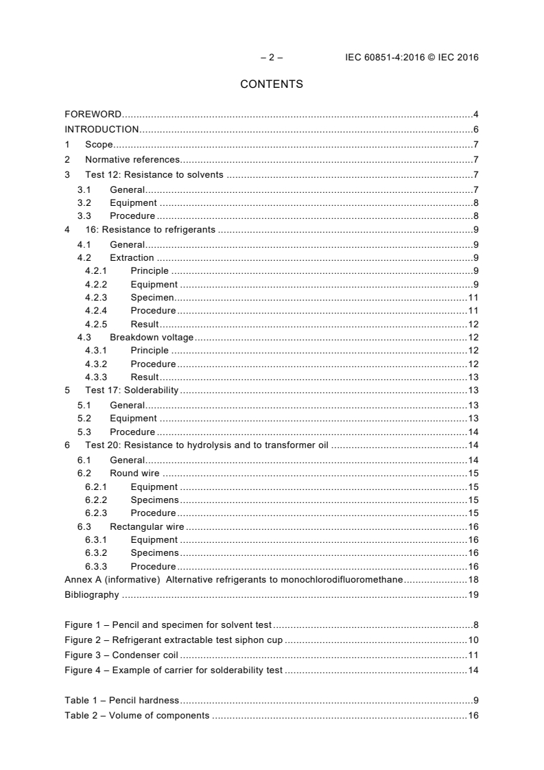
FOREWORD . 4
INTRODUCTION . 6
1 Scope . 7
2 Normative references. 7
3 Test 12: Resistance to solvents . 7
3.1 General . 7
3.2 Equipment . 8
3.3 Procedure . 8
4 16: Resistance to refrigerants . 9
4.1 General . 9
4.2 Extraction . 9
4.2.1 Principle . 9
4.2.2 Equipment . 9
4.2.3 Specimen. 11
4.2.4 Procedure . 11
4.2.5 Result . 12
4.3 Breakdown voltage . 12
4.3.1 Principle . 12
4.3.2 Procedure . 12
4.3.3 Result . 13
5 Test 17: Solderability . 13
5.1 General . 13
5.2 Equipment . 13
5.3 Procedure . 14
6 Test 20: Resistance to hydrolysis and to transformer oil . 14
6.1 General . 14
6.2 Round wire . 15
6.2.1 Equipment . 15
6.2.2 Specimens . 15
6.2.3 Procedure . 15
6.3 Rectangular wire . 16
6.3.1 Equipment . 16
6.3.2 Specimens . 16
6.3.3 Procedure . 16
Annex A (informative) Alternative refrigerants to monochlorodifluoromethane . 18
Bibliography . 19
Figure 1 – Pencil and specimen for solvent test . 8
Figure 2 – Refrigerant extractable test siphon cup . 10
Figure 3 – Condenser coil . 11
Figure 4 – Example of carrier for solderability test . 14
Table 1 – Pencil hardness . 9
Table 2 – Volume of components . 16
Table A.1 – Alternative refrigerants to R 22 . 18
– 4 – IEC 60851-4:2016 © IEC 2016
INTERNATIONAL ELECTROTECHNICAL COMMISSION
____________
WINDING WIRES – TEST METHODS –
Part 4: Chemical properties
FOREWORD
1) The International Electrotechnical Commission (IEC) is a worldwide organization for standardization comprising
all national electrotechnical committees (IEC National Committees). The object of IEC is to promote
international co-operation on all questions concerning standardization in the electrical and electronic fields. To
this end and in addition to other activities, IEC publishes International Standards, Technical Specifications,
Technical Reports, Publicly Available Specifications (PAS) and Guides (hereafter referred to as “IEC
Publication(s)”). Their preparation is entrusted to technical committees; any IEC National Committee interested
in the subject dealt with may participate in this preparatory work. International, governmental and non-
governmental organizations liaising with the IEC also participate in this preparation. IEC collaborates closely
with the International Organization for Standardization (ISO) in accordance with conditions determined by
agreement between the two organizations.
2) The formal decisions or agreements of IEC on technical matters express, as nearly as possible, an international
consensus of opinion on the relevant subjects since each technical committee has representation from all
interested IEC National Committees.
3) IEC Publications have the form of recommendations for international use and are accepted by IEC National
Committees in that sense. While all reasonable efforts are made to ensure that the technical content of IEC
Publications is accurate, IEC cannot be held responsible for the way in which they are used or for any
misinterpretation by any end user.
4) In order to promote international uniformity, IEC National Committees undertake to apply IEC Publications
transparently to the maximum extent possible in their national and regional publications. Any divergence
between any IEC Publication and the corresponding national or regional publication shall be clearly indicated in
the latter.
5) IEC itself does not provide any attestation of conformity. Independent certification bodies provide conformity
assessment services and, in some areas, access to IEC marks of conformity. IEC is not responsible for any
services carried out by independent certification bodies.
6) All users should ensure that they have the latest edition of this publication.
7) No liability shall attach to IEC or its directors, employees, servants or agents including individual experts and
members of its technical committees and IEC National Committees for any personal injury, property damage or
other damage of any nature whatsoever, whether direct or indirect, or for costs (including legal fees) and
expenses arising out of the publication, use of, or reliance upon, this IEC Publication or any other IEC
Publications.
8) Attention is drawn to the Normative references cited in this publication. Use of the referenced publications is
indispensable for the correct application of this publication.
9) Attention is drawn to the possibility that some of the elements of this IEC Publication may be the subject of
patent rights. IEC shall not be held responsible for identifying any or all such patent rights.
International Standard IEC 60851-4 has been prepared by IEC technical committee 55:
Winding wires.
This third edition cancels and replaces the second edition published in 1996,
Amendment 1:1997 and Amendment 2:2005. This edition constitutes a technical revision.
This edition includes the following significant technical changes with respect to the previous
edition:
a) revision of Test 16: Resistance to refrigerants;
b) revision of Test 17: Solderability;
c) new Annex A for alternative refrigerants to monochlorodifluoromethane (R 22).
The text of this standard is based on the following documents:
FDIS Report on voting
55/1578/FDIS 55/1580/RVD
Full information on the voting for the approval of this standard can be found in the report on
voting indicated in the above table.
This publication has been drafted in accordance with the ISO/IEC Directives, Part 2.
A list of all the parts in the IEC 60851 series, published under the general title Winding Wires
– Test methods, can be found on the IEC website.
The committee has decided that the contents of this publication will remain unchanged until
the stability date indicated on the IEC website under "http://webstore.iec.ch" in the data
related to the specific publication. At this date, the publication will be
• reconfirmed,
• withdrawn,
• replaced by a revised edition, or
• amended.
– 6 – IEC 60851-4:2016 © IEC 2016
INTRODUCTION
The IEC 60851 series is part of a group of International Standards which define insulated
wires used for windings in electrical equipment:
1) IEC 60851 series, Winding wires – Test methods;
2) IEC 60317 series, Specifications for particular types of winding wires;
3) IEC 60264 series, Packaging of winding wires.
WINDING WIRES – TEST METHODS –
Part 4: Chemical properties
1 Scope
This part of IEC 60851 specifies the following chemical properties tests:
• Test 12: Resistance to solvents;
• Test 16: Resistance to refrigerants;
• Test 17: Solderability;
• Test 20: Resistance to transformer oil.
For definitions, general notes on methods of test and the complete series of methods of test
for winding wires see IEC 60851-1.
2 Normative references
The following documents, in whole or in part, are normatively referenced in this document and
are indispensable for its application. For dated references, only the edition cited applies. For
undated references, the latest edition of the referenced document (including any
amendments) applies.
IEC 60296, Fluids for electrotechnical applications – Unused mineral insulating oils for
transformers and switchgear
IEC 60554-1:1977, Specification for cellulosic papers for electrical purposes – Part 1:
Definitions and general requirements
IEC 60851-1, Winding wires – Test methods – Part 1: General
IEC 60851-3:2009, Winding wires – Test methods – Part 3: Mechanical properties
IEC 60851-5:2008, Winding wires – Test methods – Part 5: Electrical properties
ISO 9453, Soft solder alloys – Chemical compositions and forms
3 Test 12: Resistance to solvents
3.1 General
This test is applicable to enamelled round wire with a nominal conductor diameter over
0,250 mm and to enamelled rectangular wire.
The test is not suitable for round wires with a nominal conductor diameter up to and including
0,250 mm.
Resistance to solvents is expressed by the pencil hardness of the wire after solvent
treatment.
– 8 – IEC 60851-4:2016 © IEC 2016
3.2 Equipment
The following solvents shall be used:
• standard solvent as specified below, or
• solvent as agreed between purchaser and supplier.
The standard solvent shall be a mixture of:
• 60 % by volume white spirit with maximum aromatic content of 18 %;
• 30 % by volume xylene;
• 10 % by volume butanol.
The pencil to be used shall be a lead pencil of the hardness specified in the relevant
standard. Before each test, the point of the pencil shall be sharpened with a smooth-cut file to
form an angle of 60° symmetrical about the axis of the lead according to Figure 1.
60°
60°
1 3
IEC
Key
1 Winding wire specimen
2 Pencil
3 Test surface
NOTE Angle tolerances ±5°.
Figure 1 – Pencil and specimen for solvent test
3.3 Procedure
A straight piece of wire, approximately 150 mm in length, shall be preconditioned for
(10 ± 1) min at (130 ± 3) °C in an oven with forced air circulation. A substantial length of the
wire shall then be immersed in standard solvent contained in a glass cylinder and shall be
maintained therein at a temperature of (60 ± 3) °C for a period of (30 ± 3) min. The wire shall
then be removed from the solvent. The hardness of the wire surface shall then be determined
in the following manner within a period of 30 s after removal from the solvent.
The specimen to be tested shall be laid on a smooth hard surface according to Figure 1. In
the case of rectangular wires, the test shall be carried out on the largest side of the wire. The
pencil shall be placed on the surface of the wire at an angle of approximately (60 ± 5) and the
sharpened edge shall be pressed slowly along the surface of the wire with a force of
approximately (5 ± 0,5) N.
Three tests shall be made. It shall be reported if the coating is removed with exposure of the
bare conductor.
NOTE 1 This method can also be used for testing resistance to other fluids, for example oil.
NOTE 2 Where it is desired to determine the hardness of the insulation, the hardness of the lead pencil which just
fails to remove the coating from the surface of the conductor is considered to be the hardness of the wire surface,
expressed by the pencil hardness. The pencil hardness series is as described in Table 1.
Table 1 – Pencil hardness
6B 5B 4B 3B 2B B HB H 2H 3H 4H 5H 6H 7H 8H 9H
4 5 6 7 8 9 10 11 12 13 14 15 16 17 18 19
4 16: Resistance to refrigerants
4.1 General
This test is applicable to enamelled round wire.
Resistance to refrigerant is expressed by the quantity of matter extracted from the coating of
the wire and by the breakdown voltage after exposure to a refrigerant.
NOTE 1 The data in this test method apply to monochlorodifluoromethane (refrigerant R 22). Other refrigerants
that have been determined by investigation to be appropriate for this test are provided in Annex A. When these
other refrigerants are used, it is important for safety reasons to observe the critical data for these refrigerants and
to comply with the revised test conditions during operation of the pressure vessel.
NOTE 2 Refrigerants like monochlorodifluoromethane and rinsing fluids like trichlorotrifluorethane (refrigerant
R 113) are ozone depleting chemicals (ODC). Refrigerant and rinsing fluid are agreed upon between customer and
supplier.
4.2 Extraction
4.2.1 Principle
A siphon cup containing the wire sample is placed in the pressure vessel. The extractable
matter is determined after exposure of the wire sample to the refrigerant under pressure and
at elevated temperature.
4.2.2 Equipment
The following equipment shall be used:
• siphon cup according to Figure 2, of 450 ml volume up to the siphoning level;
• pressure vessel of 2 000 ml volume with an internal diameter of approximately 100 mm
and a pressure capacity of 200 bar (20 MPa), preferably of unwelded construction and
provided with a controlled heating system;
• top closure of the vessel containing a condenser coil according to Figure 3;
• oven with forced air circulation.
– 10 – IEC 60851-4:2016 © IEC 2016
IEC
Key
Height of cup: (82 ± 5) mm
Diameter of cup: (84 ± 5) mm
Diameter of tubing: (5 ± 1) mm
Figure 2 – Refrigerant extractable test siphon cup
IEC
Figure 3 – Condenser coil
4.2.3 Specimen
Eight wire samples each containing (0,6 ± 0,1) g of insulation shall be wound into coils of
70 turns. The specimens shall be degreased and conditioned in an oven with forced air
circulation at (150 ± 3) °C for 15 min. After 30 min cooling, the eight specimens shall be
weighed together to the nearest 0,000 1 g, resulting in the total initial mass M .
4.2.4 Procedure
The eight specimens shall be placed in the siphon cup, which is suspended (25 ± 5) mm
below the condenser coil on the pressure vessel cover. The pressure vessel shall be
assembled and charged with (700 ± 25) g of distilled refrigerant free from lubricant. The
condenser water supply and drain line shall be connected and the pressure vessel shall be
heated by means of a controlled heating system with the temperature set to (75 ± 5) °C or a
lower temperature if required to comply with the conditions of the following paragraph relating
to critical pressure. The water flowing through the condenser shall be adjusted to maintain a
reflux rate of 20 to 25 discharges per hour from the siphon cup. The extraction period shall be
6 h.
– 12 – IEC 60851-4:2016 © IEC 2016
The pressure in the vessel shall not exceed 75 % of the critical pressure of the refrigerant
chosen. Therefore, prior to use, the over-pressure control valve shall be checked to ensure its
proper functioning. The heating system should be automatically deactivated if the pressure
exceeds 75 % of the critical pressure of the refrigerant chosen or if the water flow through the
condenser coil is interrupted.
At the end of the extraction period the pressure vessel shall be cooled. The refrigerant shall
be removed from the pressure vessel and recovered using suitable means such as a
refrigerant compressor and recovery system. The pressure shall be released and the pressure
vessel opened.
For the following operations, the rinsing fluid shall be distilled before use.
The specimens and siphon cup shall be rinsed with the agreed rinsing fluid, the rinse poured
into the pressure vessel and the walls of the pressure vessel washed with two successive
rinses each of 100 ml of rinsing fluid. The fluid shall then be evaporated to (5 ± 1) mm from
the bottom of the pressure vessel and recovered in a safe manner.
The liquid sample shall be transferred to a pre-dried tared aluminium weighing dish and the
pressure vessel rinsed with 15 ml of rinsing fluid, which is transferred to the dish and then
evaporated to dryness at (150 ± 3) °C for (60 to 65) min. The weighing dish shall then be
cooled to room temperature in a desiccator. The dish with the residue shall be weighed to the
nearest 0,000 1 g and the original tared mass of the same dish subtracted. The difference is
the total residue mass M of the matter extracted from the eight specimens.
The insulation on the coils shall be removed by suitable chemical means not affecting the
conductor and the bare conductors shall be dried at (150 ± 3) °C for (15 ± 1) min and cooled
to room temperature in a desiccator. They shall be weighed to the nearest 0,000 1 g and the
mass of the eight conductors together is the total conductor mass M .
4.2.5 Result
The extractable matter shall be determined according to the following equation :
M
Extractable matter = × 100 %
M − M
1 3
One test shall be made. The masses M , M , M , the refrigerant, rinsing fluid, temperature,
1 2 3
pressure of the pressure vessel and the percentage extractable matter shall be reported.
4.3 Breakdown voltage
4.3.1 Principle
A specimen prepared according to 4.4.1 of IEC 60851-5:2008 is placed in a pressure vessel
according to 4.3.2. The breakdown voltage is determined after exposure of the specimen to
the refrigerant under pressure and at elevated temperature.
4.3.2 Procedure
The specimen shall be conditioned in the oven (150 ± 3) °C for 4 h and then placed in the
pressure vessel, which shall be assembled and charged with (1 400 ± 50) g of refrigerant. The
pressure vessel shall be heated according to 4.2.4 but for a period of (72 ± 1) h.
At the end of the exposure period, the pressure vessel shall be cooled and discharged as
described under 4.2.4. When the pressure inside the tube is less than 2 bar (0,2 MPa)
absolute, the pressure vessel shall be opened and the specimen, within a period of 25 s to
30 s, transferred to the oven at a temperature of (150 ± 3) °C. The specimen shall remain in
the oven for (10 ± 1) min. After the specimen is removed from the oven and allowed to cool to
room temperature, the breakdown voltage shall be determined according to 4.4.1 of
IEC 60851-5:2008.
4.3.3 Result
Five specimens shall be tested. The five individual values shall be reported.
5 Test 17: Solderability
5.1 General
This test is applicable to enamelled round wire and bunched wire.
Solderability is expressed by the time of immersion of the specimen in a solder bath required
to remove the coating and to coat the conductor with solder.
Safety warning: Chemical hazard – Lead has been recognized by regulatory agencies to be a
hazardous substance. Primary routes of exposure are by inhalation and ingestion. The
information contained in the Material safety data sheet (MSDS) for lead, tin, flux and alcohol
must be adhered to while using, handling or disposing of these products. Adequate ventilation
or forced exhausting of solder pot vapours and products of decomposition from various
solderable insulations may be necessary to comply with environmental regulations.
Safety warning: Thermal hazard – Care shall be exercised in removing test specimens from
the solder pot to avoid skin burns.
5.2 Equipment
The following equipment shall be used:
• temperature controlled solder bath of sufficient volume to maintain a constant solder
temperature when immersing the specimen at any temperature specified in the relevant
standard. Solder composition shall be of a mass ratio of 60 parts tin to 40 parts lead or a
lead-free solder in accordance with ISO 9453 or as agreed upon between customer and
supplier; any dross which forms shall be removed from the surface of the solder before
each test; the temperature shall be controllable with ±5 °C of the temperature specified in
the relevant standard.
NOTE 1 Copper corrosion is greater when using lead free solder when compared to a tin/lead composition.
• any specimen holder that holds the wire under test free for at least 20 mm between the
points of support when immersed into the solder (See Figure 4). The material used for the
specimen holder shall be such that the solder does not undergo any contamination and the
dimensions of the holder shall not lead to significant change of the bath temperature
during immersion.
NOTE 2 Contamination of the solder due to oxidation or from copper can affect the results.
– 14 – IEC 60851-4:2016 © IEC 2016
Dimensions in millimetres
20 ±5
IEC
Figure 4 – Example of carrier for solderability test
5.3 Procedure
The specimen shall be held vertically over the centre of the bath maintained at the
temperature as specified in the relevant standard. The bottom end shall be lowered to
(35 ± 5) mm below the surface of the bath. The position at which the specimen is immersed
shall be within 10 mm of the point where the temperature is measured. After immersion for the
time specified in the relevant specification sheet, the specimen shall be moved sideways in
the bath before it is withdrawn from the solder.
The surface of the tinned wire shall be examined with a magnification of 6 to 10 times. In the
case of wire up to and including 0,100 mm nominal conductor diameter, the examination shall
be restricted to the centre (25 ± 2,5) mm free length section between the supports. In the
case of wire over 0,100 mm nominal conductor diameter and bunched wires the examination
shall be restricted to the lower 15 mm of the segment immersed in the pot.
Three specimens shall be tested. The condition of the surface of the wire shall be reported.
6 Test 20: Resistance to hydrolysis and to transformer oil
6.1 General
This test is applicable to enamelled wire.
Resistance to hydrolysis is expressed by appearance and adherence after exposure of the
specimens to transformer oil in the presence of water under pressure and at elevated
temperature.
Resistance to transformer oil is expressed by breakdown voltage and flexibility after exposure
of the specimens to transformer oil under pressure and at elevated temperature.
35 ±5 35 ±5
NOTE The water can affect the coating by hydrolytic degradation and/or by absorption. If only absorption has
occurred, drying the specimen at 125 °C ± 3 °C for 30 min prior to the breakdown voltage test will produce a
recovery of the specimen. Wire with a nominal conductor diameter between 0,800 mm and 1,500 mm has been
generally found convenient to handle and to test.
6.2 Round wire
6.2.1 Equipment
The following equipment shall be used:
• two glass tubes of 25 mm diameter and 300 mm length capable of being sealed;
• stainless steel pressure vessel of 400 ml to 500 ml volume with a pressure capacity of
6 × 10 Pa, preferably of unwelded construction and provided with a controlled heating
system;
• transformer oil according to IEC 60296;
• paper according to IEC 60554-1, type 1.
6.2.2 Specimens
The following specimens shall be prepared:
• 12 straight pieces of wire with a length of approximately two-thirds of the internal height of
pressure vessel;
• 10 twisted pair specimens prepared in accordance with 4.4.1 of IEC 60851-5:2008 for
nominal conductor diameter up to and including 2,500 mm or 10 straight specimens tested
in accordance with 4.5.1 of IEC 60851-5:2008 for nominal conductor diameter over
2,500 mm;
• 3 mandrel-wound specimens prepared in accordance with 5.1.1 of IEC 60851-3:2009 for
nominal conductor diameter up to and including 1,600 mm or 3 straight specimens tested
in accordance with 5.2 of IEC 60851-3:2009 for a nominal conductor diameter over
1,600 mm.
6.2.3 Procedure
6.2.3.1 Resistance to hydrolysis
Six straight pieces of wire prepared according to 6.2.2 are placed in the pressure vessel
together with a quantity of de-aerated dry transformer oil sufficient to occupy (52,5 ± 2,5) %
of the volume of the pressure vessel. The pressure vessel shall be sealed and heated to
(150 ± 3) °C for (24 ± 1) h, after which it is allowed to cool to room temperature before
opening. The specimens shall be examined with normal vision. The test shall be repeated with
a quantity of water equal to (0,3 ± 0,1) % of the volume of oil used being added to the
pressure vessel.
One test shall be made. Any changes in appearance and adherence shall be reported.
6.2.3.2 Resistance to transformer oil
Depending on the diameter and according to 6.2.2, the pressure vessel shall contain 10
twisted pair or straight specimens, three mandrel-wound or straight specimens and extra
pieces of wire to arrive at the volume of coating specified in Table 2.
NOTE The total mass of wire in grams to provide the required volume of enamel can be calculated approximately
by:
Y × V
M =
600 × δ × D
where
V is the volume of the pressure vessel in millilitres;
– 16 – IEC 60851-4:2016 © IEC 2016
Y is the mass of 1 m of wire in grams;
δ is the increase in diameter due to the coating in millimetres;
D is the overall diameter of the wire in millimetres.
The pressure vessel shall be charged in accordance with the components and quantities
specified in Table 2. Immediately prior to their addition, the oil and paper shall be dried and
the oil de-aerated at a pressure of 2 kPa for (16 ± 1) h at (90 ± 3) °C or for (4 ± 0,30) h at
(105 ± 3) °C.
Table 2 – Volume of components
Component Container volume
%
Transformer oil
65 ± 5
Paper
4 ± 1
Coating 0,275 ± 0,075
a
Steel
a
By agreement between purchaser and supplier.
The sealed pressure vessel shall be heated to the class temperature of the wire ±3 °C, or to
(150 ± 3) °C, if class temperature is higher than 150 °C, and maintained for (1 000 ± 10) h.
The pressure vessel shall then be allowed to cool to room temperature, discharged and
opened. Five of the 10 specimens shall be tested at (105 ± 3) °C for breakdown voltage with
the specimens in air in accordance with either 4.4.2 or 4.5.2 of IEC 60851-5:2008, depending
on the conductor diameter. The remaining five of the 10 specimens shall be dried at
(125 ± 3) °C for (30 ± 5) min, allowed to cool to room temperature and then tested at
(105 ± 3) °C for breakdown voltage in air in accordance with either 4.4.2 or 4.5.2 of
IEC 60851-5:2008, depending on the conductor diameter.
The three specimens shall be examined for cracks according to either 5.1.1.1 or 5.2 of
IEC 60851-3:2009, depending on the conductor diameter.
One test shall be made. The individual values of breakdown voltage and any cracks shall be
reported.
6.3 Rectangular wire
6.3.1 Equipment
Equipment according to 6.2.1 shall be used.
6.3.2 Specimens
The following specimens shall be prepared:
• 10 straight pieces of wire with a length of approximately two-thirds of the internal height of
pressure vessel;
• four U-shaped specimens prepared in accordance with 4.7.1 of IEC 60851-5:2008;
• two mandrel bent specimens prepared in accordance with 5.1.2 of IEC 60851-3:2009.
6.3.3 Procedure
6.3.3.1 Resistance to hydrolysis
Each of the tubes shall be charged with five straight pieces of wire according to 6.3.2 and
80 ml de-aerated dry transformer oil. To one of the tubes, (0,24 ± 0,01) ml of distilled water
shall be added. The two tubes shall be sealed and placed in an oven for 24 h at (150 ± 3) °C.
The tubes shall then be removed from the oven, and then allowed to cool down to room
temperature and opened. The specimens shall be examined with normal vision.
One test shall be made. Any changes in appearance and adherence shall be reported.
6.3.3.2 Resistance to transformer oil
The pressure vessel shall contain four U-shaped specimens, two mandrel bent specimens and
extra pieces of wire to arrive at the volume of coating specified in Table 2.
NOTE The total mass of wire in grams to provide the required volume of enamel can be calculated approximately
by:
Y × V
M =
385 × δ × (W + T )
where
V is the volume of the pressure vessel in millilitres;
Y is the mass of 1 m of wire in grams;
δ is the increase in thickness due to the coating in millimetres;
W is the overall width of the wire in millimetres;
T is the overall thickness of the wire in millimetres.
The pressure vessel shall then be charged, in accordance with the quantities specified in
Table 2, with oil and paper which shall have been dried separately immediately prior to
addition at a pressure of maximum 2 kPa for (16 ± 1) h at (90 ± 3) °C or for (4 ± 0,1) h at
(105 ± 3) °C. The sealed pressure vessel shall be heated to the class temperature of the wire
±3 °C, or to (150 ± 3) °C if class temperature is higher than 150 °C, and maintained for
(1 000 ± 10) h. The pressure vessel shall then be allowed to cool to room temperature,
discharged and opened. Two of the U-shaped specimens shall be tested at (105 ± 3) °C for
breakdown voltage in air in accordance with 4.7.2 of IEC 60851-5:2008. The remaining two of
the U-shaped specimens shall be dried at (125 ± 3) °C for (30 ± 5) min, allowed to cool to
room temperature and then tested at (105 ± 3) °C for breakdown voltage in air according to
4.7.2 of IEC 60851-5:2008.
The mandrel-bent specimens shall be examined for cracks according to 5.1.2 of
IEC 60851-3:2009.
One test shall be made. The individual values of breakdown voltage and any cracks shall be
reported.
– 18 – IEC 60851-4:2016 © IEC 2016
Annex A
(informative)
Alternative refrigerants to monochlorodifluoromethane
Table A.1 provides a list of alternative refrigerants to monochlorodifluoromethane (R 22) that
have been found through investigation to be suitable for use in Test 16.
For safety purposes and for their proper application during testing, observation of critical data
in this table is recommended.
Table A.1 – Alternative refrigerants to R 22
Composition Critical Critical
Formula Boiling Point
(Weight percent) Pressure Temperature
Refrigerant
°C MPa °C
Monochlorodiflouromethane
R 22 CHCIF –41 5,0 96,2
R 134a 1,1,1,2 Tetrafluoroethane CH FCF –26 4,1 101,1
2 3
Pentafluoroethane – 44 % CF -CHF
3 2
R 404a 1,1,1 Trifluoroethane – 52 % CF -CH –47 3,7 72,1
3 3
1,1,1,2 Tetrafluoroethane – 4 % CF CH F
3 2
R 32 − 23 % CH F
2 2
R 407c R 125 − 25 % C HF –44 4,6 86,7
2 5
R 134a − 52 % CH FCF
2 3
R 32 − 50 % CH F
2 2
R 410a –52 4,9 71,8
R 125 − 50 % C HF
2 5
R 125 – 50 % C HF
2 5
R 507 –47 3,8 70,9
R 134a – 50 % CH FCF
2 3
Consultation with the refrigerant manufacturer is recommended for updated information.
Bibliography
IEC 60264 (all parts), Packaging of winding wires
IEC 60317 (all parts), Specifications for particular types of winding wires
IEC 60851 (all parts), Winding wires – Test methods
_____________
– 20 – IEC 60851-4:2016 © IEC 2016
SOMMAIRE
AVANT-PROPOS . 22
INTRODUCTION . 24
1 Domaine d’application. 25
2 Références normatives . 25
3 Essai 12: Résistance aux solvants . 25
3.1 Généralités . 25
3.2 Equipement . 26
3.3 Procédure . 26
4 Essai 16: Résistance aux réfrigérants . 27
4.1 Généralités . 27
4.2 Extraction . 27
4.2.1 Principe . 27
4.2.2 Equipement . 27
4.2.3 Eprouvette . 29
4.2.4 Procédure . 29
4.2.5 Résultats . 30
4.3 Tension de claquage . 30
4.3.1 Principe . 30
4.3.2 Procédure . 30
4.3.3 Résultats . 31
5 Essai 17: Brasabilité . 31
5.1 Généralités . 31
5.2 Equipement . 31
5.3 Procédure . 32
6 Essai 20: Résistance à l'hydrolyse et à l'huile de transformateur . 32
6.1 Généralités . 32
6.2 Fil de section circulaire . 33
6.2.1 Equipement .
...