

IEC 61800-9-1:2026
(Main)Adjustable speed electrical power drive systems - Part 9-1: Ecodesign for motor systems - General requirements for setting energy efficiency standards
- Abstract
IEC 61800-9-1:2026 specifies the general methodology to energy efficiency standardization for any extended product by using the guidance of the extended product approach (EPA). It enables product committees for driven equipment connected to motor systems (so called extended products) to interface with the relative power losses of the connected motor system (e.g. power drive system) in order to calculate the system energy efficiency for the whole application. This is based on specified calculation models for speed/load profiles, the duty profiles and relative power losses of appropriate torque versus speed operating points. This document is applicable to motor systems operated by a motor starter or by a converter (power drive system). This document does not specify requirements for environmental impact declarations. Power drive systems designed to drive DC motors are not included in the scope of this document. This document is a group energy efficiency publication as defined in IEC Guide 118 with the energy efficiency function to establish a clear and simple system methodology for the comparison of the energy performance of motor systems to help product and system improvement.
This edition includes the following significant technical changes with respect to the previous edition:
a) addition of Annex D - Examples of indexing and evaluation of energy consumption;
b) correction of errors of symbols in several formulas and tables.
- Status
- Published
- Publication Date
- 03-Nov-2026
- Technical Committee
- SC 22G - Adjustable speed electric power drive systems (PDS)
- Drafting Committee
- WG 18 - TC 22/SC 22G/WG 18
- Current Stage
- PPUB - Publication issued
- Start Date
- 04-Nov-2026
- Completion Date
- 01-Dec-2026
Buy Documents
REDLINE IEC 61800-9-1:2026 RLV - Adjustable speed electrical power drive systems - Part 9-1: Ecodesign for motor systems - General requirements for setting energy efficiency standards
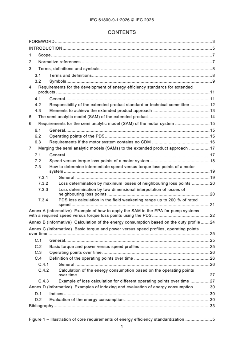
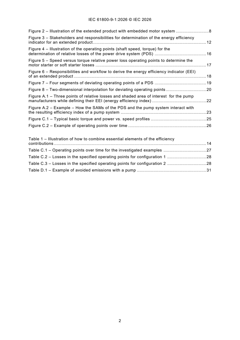
iec61800-9-1{ed2.0}en - Adjustable speed electrical power drive systems - Part 9-1: Ecodesign for motor systems - General requirements for setting energy efficiency standards
iec61800-9-1{ed2.0}fr - Entraînements électriques de puissance à vitesse variable - Partie 9-1: Écoconception des systèmes moteurs - Exigences générales pour l’élaboration des normes d’efficacité énergétique
Relations
- Effective Date
- 10-Nov-2023
Buy Documents
REDLINE IEC 61800-9-1:2026 RLV - Adjustable speed electrical power drive systems - Part 9-1: Ecodesign for motor systems - General requirements for setting energy efficiency standards
iec61800-9-1{ed2.0}en - Adjustable speed electrical power drive systems - Part 9-1: Ecodesign for motor systems - General requirements for setting energy efficiency standards
iec61800-9-1{ed2.0}fr - Entraînements électriques de puissance à vitesse variable - Partie 9-1: Écoconception des systèmes moteurs - Exigences générales pour l’élaboration des normes d’efficacité énergétique
Get Certified
Connect with accredited certification bodies for this standard

IMQ S.p.A. (Certification)
Italian electrical product certification.

SLG Prüf- und Zertifizierungs GmbH
German testing and certification body.

UL Solutions
Global safety science company with testing, inspection and certification.
Sponsored listings
Frequently Asked Questions
IEC 61800-9-1:2026 is a standard published by the International Electrotechnical Commission (IEC). Its full title is "Adjustable speed electrical power drive systems - Part 9-1: Ecodesign for motor systems - General requirements for setting energy efficiency standards". This standard covers: IEC 61800-9-1:2026 specifies the general methodology to energy efficiency standardization for any extended product by using the guidance of the extended product approach (EPA). It enables product committees for driven equipment connected to motor systems (so called extended products) to interface with the relative power losses of the connected motor system (e.g. power drive system) in order to calculate the system energy efficiency for the whole application. This is based on specified calculation models for speed/load profiles, the duty profiles and relative power losses of appropriate torque versus speed operating points. This document is applicable to motor systems operated by a motor starter or by a converter (power drive system). This document does not specify requirements for environmental impact declarations. Power drive systems designed to drive DC motors are not included in the scope of this document. This document is a group energy efficiency publication as defined in IEC Guide 118 with the energy efficiency function to establish a clear and simple system methodology for the comparison of the energy performance of motor systems to help product and system improvement. This edition includes the following significant technical changes with respect to the previous edition: a) addition of Annex D - Examples of indexing and evaluation of energy consumption; b) correction of errors of symbols in several formulas and tables.
IEC 61800-9-1:2026 specifies the general methodology to energy efficiency standardization for any extended product by using the guidance of the extended product approach (EPA). It enables product committees for driven equipment connected to motor systems (so called extended products) to interface with the relative power losses of the connected motor system (e.g. power drive system) in order to calculate the system energy efficiency for the whole application. This is based on specified calculation models for speed/load profiles, the duty profiles and relative power losses of appropriate torque versus speed operating points. This document is applicable to motor systems operated by a motor starter or by a converter (power drive system). This document does not specify requirements for environmental impact declarations. Power drive systems designed to drive DC motors are not included in the scope of this document. This document is a group energy efficiency publication as defined in IEC Guide 118 with the energy efficiency function to establish a clear and simple system methodology for the comparison of the energy performance of motor systems to help product and system improvement. This edition includes the following significant technical changes with respect to the previous edition: a) addition of Annex D - Examples of indexing and evaluation of energy consumption; b) correction of errors of symbols in several formulas and tables.
IEC 61800-9-1:2026 is classified under the following ICS (International Classification for Standards) categories: 29.130.01 - Switchgear and controlgear in general; 29.160.30 - Motors; 29.200 - Rectifiers. Convertors. Stabilized power supply. The ICS classification helps identify the subject area and facilitates finding related standards.
IEC 61800-9-1:2026 has the following relationships with other standards: It is inter standard links to IEC 61800-9-1:2017. Understanding these relationships helps ensure you are using the most current and applicable version of the standard.
IEC 61800-9-1:2026 is available in PDF format for immediate download after purchase. The document can be added to your cart and obtained through the secure checkout process. Digital delivery ensures instant access to the complete standard document.
Standards Content (Sample)
IEC 61800-9-1 ®
Edition 2.0 2026-11
INTERNATIONAL
STANDARD
REDLINE VERSION
HORIZONTAL PUBLICATION
GROUP ENERGY EFFICIENCY PUBLICATION
Adjustable speed electrical power drive systems -
Part 9-1: Ecodesign for power drive motor systems, motor starters,
power electronics and their driven applications -
General requirements for setting energy efficiency standards for power driven
equipment using the extended
ICS 29.200; 29.130.01; 29.160.30 ISBN 978-2-8327-1604-5
All rights reserved. Unless otherwise specified, no part of this publication may be reproduced or utilized in any form or
by any means, electronic or mechanical, including photocopying and microfilm, without permission in writing from either
IEC or IEC's member National Committee in the country of the requester. If you have any questions about IEC copyright
or have an enquiry about obtaining additional rights to this publication, please contact the address below or your local
IEC member National Committee for further information.
IEC Secretariat Tel.: +41 22 919 02 11
3, rue de Varembé info@iec.ch
CH-1211 Geneva 20 www.iec.ch
Switzerland
About the IEC
The International Electrotechnical Commission (IEC) is the leading global organization that prepares and publishes
International Standards for all electrical, electronic and related technologies.
About IEC publications
The technical content of IEC publications is kept under constant review by the IEC. Please make sure that you have the
latest edition, a corrigendum or an amendment might have been published.
IEC publications search - IEC Products & Services Portal - products.iec.ch
webstore.iec.ch/advsearchform Discover our powerful search engine and read freely all the
The advanced search enables to find IEC publications by a publications previews, graphical symbols and the glossary.
variety of criteria (reference number, text, technical With a subscription you will always have access to up to date
committee, …). It also gives information on projects, content tailored to your needs.
replaced and withdrawn publications.
Electropedia - www.electropedia.org
IEC Just Published - webstore.iec.ch/justpublished The world's leading online dictionary on electrotechnology,
Stay up to date on all new IEC publications. Just Published containing more than 22 500 terminological entries in English
details all new publications released. Available online and and French, with equivalent terms in 25 additional languages.
once a month by email. Also known as the International Electrotechnical Vocabulary
(IEV) online.
IEC Customer Service Centre - webstore.iec.ch/csc
If you wish to give us your feedback on this publication or
need further assistance, please contact the Customer
Service Centre: sales@iec.ch.
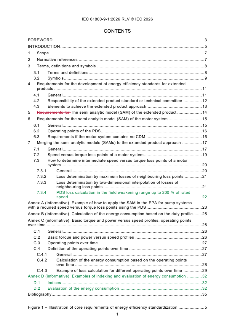
CONTENTS
FOREWORD . 3
INTRODUCTION . 5
1 Scope . 7
2 Normative references . 7
3 Terms, definitions and symbols . 8
3.1 Terms and definitions. 8
3.2 Symbols . 9
4 Requirements for the development of energy efficiency standards for extended
products . 11
4.1 General . 11
4.2 Responsibility of the extended product standard or technical committee . 12
4.3 Elements to achieve the extended product approach . 13
5 Requirements for The semi analytic model (SAM) of the extended product . 14
6 Requirements for the semi analytic model (SAM) of the motor system . 15
6.1 General . 15
6.2 Operating points of the PDS. 16
6.3 Requirements if the motor system contains no CDM . 16
7 Merging the semi analytic models (SAMs) to the extended product approach . 17
7.1 General . 17
7.2 Speed versus torque loss points of a motor system . 19
7.3 How to determine intermediate speed versus torque loss points of a motor
system . 20
7.3.1 General . 20
7.3.2 Loss determination by maximum losses of neighbouring loss points . 21
7.3.3 Loss determination by two-dimensional interpolation of losses of
neighbouring loss points . 21
7.3.4 PDS loss calculation in the field weakening range up to 200 % of rated
speed . 22
Annex A (informative) Example of how to apply the SAM in the EPA for pump systems
with a required speed versus torque loss points using the PDS . 23
Annex B (informative) Calculation of the energy consumption based on the duty profile . 25
Annex C (informative) Basic torque and power versus speed profiles, operating points
over time . 26
C.1 General . 26
C.2 Basic torque and power versus speed profiles . 26
C.3 Operating points over time . 27
C.4 Definition of the operating points over time . 27
C.4.1 General . 27
C.4.2 Calculation of the energy consumption based on the operating points
over time . 28
C.4.3 Example of loss calculation for different operating points over time . 29
Annex D (informative) Examples of indexing and evaluation of energy consumption . 32
D.1 Indices . 32
D.2 Evaluation of the energy consumption . 32
Bibliography . 35
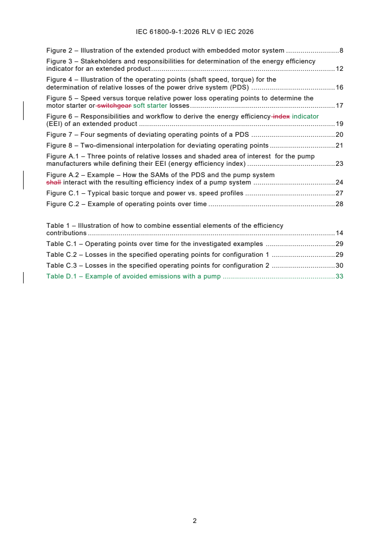
Figure 1 – Illustration of core requirements of energy efficiency standardization . 5
Figure 2 – Illustration of the extended product with embedded motor system . 8
Figure 3 – Stakeholders and responsibilities for determination of the energy efficiency
indicator for an extended product . 12
Figure 4 – Illustration of the operating points (shaft speed, torque) for the
determination of relative losses of the power drive system (PDS) . 16
Figure 5 – Speed versus torque relative power loss operating points to determine the
motor starter or switchgear soft starter losses . 17
Figure 6 – Responsibilities and workflow to derive the energy efficiency index indicator
(EEI) of an extended product . 19
Figure 7 – Four segments of deviating operating points of a PDS . 20
Figure 8 – Two-dimensional interpolation for deviating operating points . 21
Figure A.1 – Three points of relative losses and shaded area of interest for the pump
manufacturers while defining their EEI (energy efficiency index) . 23
Figure A.2 – Example – How the SAMs of the PDS and the pump system
shall interact with the resulting efficiency index of a pump system . 24
Figure C.1 – Typical basic torque and power vs. speed profiles . 27
Figure C.2 – Example of operating points over time . 28
Table 1 – Illustration of how to combine essential elements of the efficiency
contributions . 14
Table C.1 – Operating points over time for the investigated examples . 29
Table C.2 – Losses in the specified operating points for configuration 1 . 29
Table C.3 – Losses in the specified operating points for configuration 2 . 30
Table D.1 – Example of avoided emissions with a pump . 33
INTERNATIONAL ELECTROTECHNICAL COMMISSION
____________
Adjustable speed electrical power drive systems -
Part 9-1: Ecodesign for power drive motor systems, motor starters,
power electronics and their driven applications -
General requirements for setting energy efficiency standards for power
driven equipment using the extended
FOREWORD
1) The International Electrotechnical Commission (IEC) is a worldwide organization for standardization comprising
all national electrotechnical committees (IEC National Committees). The object of IEC is to promote international
co-operation on all questions concerning standardization in the electrical and electronic fields. To this end and
in addition to other activities, IEC publishes International Standards, Technical Specifications, Technical Reports,
Publicly Available Specifications (PAS) and Guides (hereafter referred to as “IEC Publication(s)”). Their
preparation is entrusted to technical committees; any IEC National Committee interested in the subject dealt with
may participate in this preparatory work. International, governmental and non-governmental organizations liaising
with the IEC also participate in this preparation. IEC collaborates closely with the International Organization for
Standardization (ISO) in accordance with conditions determined by agreement between the two organizations.
2) The formal decisions or agreements of IEC on technical matters express, as nearly as possible, an international
consensus of opinion on the relevant subjects since each technical committee has representation from all
interested IEC National Committees.
3) IEC Publications have the form of recommendations for international use and are accepted by IEC National
Committees in that sense. While all reasonable efforts are made to ensure that the technical content of IEC
Publications is accurate, IEC cannot be held responsible for the way in which they are used or for any
misinterpretation by any end user.
4) In order to promote international uniformity, IEC National Committees undertake to apply IEC Publications
transparently to the maximum extent possible in their national and regional publications. Any divergence between
any IEC Publication and the corresponding national or regional publication shall be clearly indicated in the latter.
5) IEC itself does not provide any attestation of conformity. Independent certification bodies provide conformity
assessment services and, in some areas, access to IEC marks of conformity. IEC is not responsible for any
services carried out by independent certification bodies.
6) All users should ensure that they have the latest edition of this publication.
7) No liability shall attach to IEC or its directors, employees, servants or agents including individual experts and
members of its technical committees and IEC National Committees for any personal injury, property damage or
other damage of any nature whatsoever, whether direct or indirect, or for costs (including legal fees) and
expenses arising out of the publication, use of, or reliance upon, this IEC Publication or any other IEC
Publications.
8) Attention is drawn to the Normative references cited in this publication. Use of the referenced publications is
indispensable for the correct application of this publication.
9) IEC draws attention to the possibility that the implementation of this document may involve the use of (a)
patent(s). IEC takes no position concerning the evidence, validity or applicability of any claimed patent rights in
respect thereof. As of the date of publication of this document, IEC had not received notice of (a) patent(s), which
may be required to implement this document. However, implementers are cautioned that this may not represent
the latest information, which may be obtained from the patent database available at https://patents.iec.ch. IEC
shall not be held responsible for identifying any or all such patent rights.
This redline version of the official IEC Standard allows the user to identify the changes made
to the previous edition IEC 61800-9-1:2017. A vertical bar appears in the margin wherever a
change has been made. Additions are in green text, deletions are in strikethrough red text.
IEC 61800-9-1 has been prepared by subcommittee 22G: Adjustable speed electric drive
systems (PDS), of IEC technical committee 22: Power electronic systems and equipment. It is
an International Standard.
It has the status of a group energy efficiency publication in accordance with IEC Guide 118.
This second edition cancels and replaces the first edition published in 2017. This edition
constitutes a technical revision.
This edition includes the following significant technical changes with respect to the previous
edition:
a) addition of Annex D - Examples of indexing and evaluation of energy consumption;
b) correction of errors of symbols in several formulas and tables.
The text of this International Standard is based on the following documents:
Draft Report on voting
22G/525/CDV 22G/536/RVC
Full information on the voting for its approval can be found in the report on voting indicated in
the above table.
The language used for the development of this International Standard is English.
This document was drafted in accordance with ISO/IEC Directives, Part 2, and developed in
accordance with ISO/IEC Directives, Part 1 and ISO/IEC Directives, IEC Supplement, available
at www.iec.ch/members_experts/refdocs. The main document types developed by IEC are
described in greater detail at www.iec.ch/publications.
Words in bold in the text are defined in Clause 3.
A list of all parts in the IEC 61800 series, published under the general title Adjustable speed
electrical power drive systems, can be found on the IEC website.
The committee has decided that the contents of this document will remain unchanged until the
stability date indicated on the IEC website under webstore.iec.ch in the data related to the
specific document. At this date, the document will be
– reconfirmed,
– withdrawn, or
– revised.
INTRODUCTION
IEC SC 22G includes the standardization task force for dealing with energy efficiency of motor
systems. It has close collaboration with several other technical committees (for example,
IEC TC 2, IEC SC 121A).
IEC SC 22G maintains responsibility for all relevant aspects in the field of energy efficiency and
ecodesign requirements for power electronics, switchgear, control gear and power drive
systems and their industrial applications.
The core requirements of energy efficiency standardization are illustrated in Figure 1. The work
has been agreed to provide a reasonable target as a best compromise.
Figure 1 – Illustration of core requirements
of energy efficiency standardization
The IEC 61800 series does not deal with mechanical engineering components.
NOTE Geared motors (motors with directly adapted gearboxes) are treated like power drive systems (converter plus
motor). See IEC 60034-30-1 for classification of the losses of a geared motor. The efficiency classes of gearboxes
as individual components are under consideration.
IEC 61800-9-1 is a subpart of the IEC 61800 series, which has the following structure:
– Part 1: General requirements - Rating specifications for low voltage adjustable speed DC
power drive systems
– Part 2: General requirements - Rating specifications for low voltage adjustable speed AC
power drive systems
– Part 3: EMC requirements and specific test methods for PDS and machine tools
– Part 4: General requirements – Rating specifications for a.c. power drive systems above
1 000 V a.c. and not exceeding 35 kV
– Part 5: Safety requirements
– Part 6: Guide for determination of types of load duty and corresponding current ratings
– Part 7: Generic interface and use of profiles for power drive systems
– Part 8: Specification of voltage on the power interface
– Part 9: Ecodesign for power drive systems, motor starters, power electronics and their driven
applications motor systems
Each part isSome parts are further subdivided into several subparts, published either as
International Standards or as Technical Specifications or Technical Reports, some of which
have already been published. Others will be published with the part number followed by a dash
and a second number identifying the subdivision (for example, IEC 61800-9-2).
This part of IEC 61800-9 is an International Standard for characterizing the energy efficiency
of motor systems when supplied by a motor starter or by a variable voltage/frequency
converter. The goal of this document is to establish a clear and simple system for the
comparison of the energy performance of motor systems that can help manufacturers to
improve their products, to give users the necessary transparency and information and to provide
a robust reference base for regulators and minimum energy performance standards.
The IEC 61800-9 series (ecodesign for power drive motor systems, motor starters, power
electronics and their driven applications) consists of the following subparts:
– Subpart 9-1: General requirements for setting energy efficiency standards for power driven
equipment using the extended product approach (EPA) and semi analytic model (SAM)
– Subpart 9-2: Energy efficiency indicators for power drive systems and motor starters
determination and classification
1 Scope
This part of IEC 61800 specifies the general methodology to energy efficiency standardization
for any extended product by using the guidance of the extended product approach (EPA).
It enables product committees for driven equipment connected to motor systems (so called
extended products) to interface with the relative power losses of the connected motor system
(e.g. power drive system) in order to calculate the system energy efficiency for the whole
application.
This is based on specified calculation models for speed/load profiles, the duty profiles and
relative power losses of appropriate torque versus speed operating points.
This document specifies the methodology of determination of losses of the extended product
and its sub-parts.
This document is applicable to motor systems operated by a motor starter or by a converter
(power drive system).
This document does not specify requirements for environmental impact declarations.
Power drive systems designed to drive DC motors are not included in the scope of this
document.
This document is a group energy efficiency publication as defined in IEC Guide 118 with the
energy efficiency function to establish a clear and simple system methodology for the
comparison of the energy performance of motor systems to help product and system
improvement.
2 Normative references
The following documents are referred to in the text in such a way that some or all of their content
constitutes requirements of this document. For dated references, only the edition cited applies.
For undated references, the latest edition of the referenced document (including any
amendments) applies.
IEC 60050-161, International Electrotechnical Vocabulary - Part 161: Electromagnetic
compatibility (available at www.electropedia.org)
IEC 60034-2-1:2014, Rotating electrical machines – Part 2-1: Standard methods for determining
losses and efficiency from tests (excluding machines for traction vehicles)
IEC TS 60034-2-3:2024, Rotating electrical machines - Part 2-3: Specific test methods for
determining losses and efficiency of converter-fed AC induction motors
IEC 61800-9-2:2016, Adjustable speed electrical power drive systems -Part 9-2: Ecodesign for
power drive systems, motor starters, power electronics and their driven applications - Energy
efficiency indicators for power drive systems and motor starters
IEC 61800-9-2:2023, Adjustable speed electrical power drive systems (PDS) - Part 9-2:
Ecodesign for motor systems - Energy efficiency determination and classification
IEC 61800-9-2:2023/AMD1:2025
IEC Guide 118, Preparation of basic and group energy efficiency publications including energy
efficiency aspects
3 Terms, definitions and symbols
3.1 Terms and definitions
For the purposes of this document, the terms and definitions given in IEC 60050-161 and the
following apply.
ISO and IEC maintain terminology databases for use in standardization at the following
addresses:
– IEC Electropedia: available at https://www.electropedia.org/
– ISO Online browsing platform: available at https://www.iso.org/obp
3.1.1
duty profile
load-time profile
annual distribution load points with associated time fraction
Note 1 to entry: The duty profile may consist of only one operating point.
3.1.2
energy efficiency index indicator
EEI
generic value describing the energy efficiency of an application, resulting from the extended
product approach (EPA) extended product operating with a specified duty profile
Note 1 to entry: Examples of EEI include the energy efficiency index defined by the pump industry to characterize
pump systems, or the weighted average electrical power described in Annex B.
3.1.3
extended product
EP
driven equipment together with its connected motor system (e.g. a PDS)
Note 1 to entry: See Figure 2.
Figure 2 – Illustration of the extended product with embedded motor system
3.1.4
extended product approach
EPA
methodology to determine the energy eficiency index efficiency indicator (EEI) of the
extended product (EP) using the speed torque profiles of the driven equipment, the relative
power losses of the motor system and the duty profile of the application
Note 1 to entry: The fan energy index (FEI) is used as the energy index for the fan industry.
3.1.5
extended product standard committee
body in charge of the standardization of the energy efficiency indicators for a given extended
product
Note 1 to entry: Extended product committees can be ISO or IEC technical committees, or other relevant bodies.
3.1.6
load-time profile
fraction of time spent at each operating point during the total operating time or a complete cycle
of operation of the extended product
Note 1 to entry: Typically, a load-time profile is represented by a histogram.
Note 2 to entry: The standby mode can be included in the load-time profile.
3.1.7
motor control equipment
complete drive module (CDM) or motor starter
3.1.8
motor system
motor control equipment and motor
3.1.9
semi analytic model
SAM
determination model for the losses of a motor system or driven equipment
Note 1 to entry: SAMs include physical and mathematical parameters and calculation algorithms of the subparts of
an EP. SAMs are necessary to determine the typical relative power losses of the subparts of an EP in order to
determine its overall losses.
3.1.10
transmission
any component (coupling, Gear box, etc.) which connects the motor shaft to the load machine
(e.g. fan, pump): coupling, gearbox or compressor
Note 1 to entry: A component can be for example a coupling or a gear box.
3.2 Symbols
3.2.1
E
electrical
electrical energy [kWh] consumption of an application during a certain runtime period
3.2.2
k
P
ratio of the weighted average electrical power consumption P of an application to the
electrical
reference power consumption P
reference
3.2.3
P
electrical
power consumption [kW] of an application over time
3.2.4
P
electrical Max
power consumption [kW] at 100 % speed and 100 % load
3.2.5
P
i
power consumption [kW] at operating point i
3.2.6
P
L,control
power losses [kW] of the motor control equipment
3.2.7
P
n
nominal power of an equipment which is typical for its population of the same rating
Note 1 to entry: See IEC 60034-1 for motors.
3.2.8
P
out,CDM
output power [kW] of CDM obtained from the power loss measurement
3.2.9
P
out,PDS
output power [kW] of a PDS obtained from the power loss measurement
3.2.10
P
r
rated power of equipment which is assigned by its manufacturer
3.2.11
P
reference
power consumption used for reference, defined by the extended product committee
3.2.12
P
L
electrical power losses
Note 1 to entry: In P , P and P , the index "CDM" refers to the complete drive module, "Mot" refers to
L,CDM L,Mot L,Aux
the motor, and "Aux" refers to the auxiliary devices like cables, transformers or filters. The relative power losses are
the per unit losses relative to the nominal power of the device.
3.2.13
P
L,CDM
power losses of a CDM
3.2.14
P
L,CDM,determined
power losses of a CDM from the power loss determination method
3.2.15
P
L,CDM,relative
power losses of a CDM, with reference to its rated apparent power
3.2.16
P
L,inverter
power losses in the inverter section of a CDM
3.2.17
P
L,PDS,determined
power losses of PDS from the power loss determination method
3.2.18
P
L,Mot
total losses of a motor according to IEC 60034-2-1:2014, method 2-1-1B IEC 60034-2-3 when
supplied by a converter (non-sinusoidal power supply)
3.2.19
t
W
working time of an equipment
3.2.20
T
i
torque [Nm] at operating point i
3.2.21
TimeFraction
i
TF
i
percentage of time (time fraction) an extended product is operated at one specific operating
point i
4 Requirements for the development of energy efficiency standards for
extended products
4.1 General
This document specifies a methodology to determine the energy efficiency index indicator of
an application, based on the concept of semi analytic models (SAMs). The methodology shall
be referred to as an extended product approach (EPA).
The responsibilities and tasks of the different stakeholders creating or using these extended
products standards, as well as the data flows in-between, are specified as follows.
a) Specific information about the equipment shall be considered:
1) The torque versus speed profile of the driven load as specified by the load manufacturer
or other pertinent entity (e.g. regulatory authority, other specified organization) .
2) The losses of the motor system or its constituents (motor, CDM or motor starter) at
reference part-load operating points. These shall be provided by the different
manufacturers as specified in IEC 61800-9-2.
b) Information about the driven equipment application shall be considered:
1) The duty profile of the driven equipment. Pertinent entities can for example define
typical applications of their extended products, each associated with a typical duty
profile.
c) The extended product approach shall be used to determine permits the determination of
an energy efficiency indicator (losses, efficiency, energy consumption, etc.):
– IEC 61800-9-2 specifies the methods for the determination of losses of the motor system
using measurement and/or calculations.
1) Other pertinent entity(ies) (e.g. regulatory authority, other specified organization) shall
define how to combine the losses of the motor system and the losses of the load, to
obtain an overall energy efficiency index indicator for the extended product within
the defined application.
2) IEC TR 62837 suggests the definition and use of key performance indicators (KPIs) for
energy efficiency through automation systems that are in accordance with the principle
of this document.
The interactions between the different stakeholders are shown in Figure 3.
NOTE 1 Motor and CDM manufacturers can provide data directly to the motor system manufacturer.
NOTE 2 If the motor system is based on a starter, then only the motor losses are needed as input to the EPA.
Figure 3 – Stakeholders and responsibilities for determination
of the energy efficiency indicator for an extended product
4.2 Responsibility of the extended product standard or technical committee
Based on the general principles described in this document, it shall be the responsibility of the
entity(ies) dealing with a type of extended product (e.g. regulatory authority, other specified
organization) to specify the semi analytic model of the driven load and of the extended
product for the product-specific application(s).
Pertinent entity(ies) (e.g. regulatory authority, other specified organization) shall can specify
and standardize
– one or more torque versus speed profiles (load profiles) as described in Annex C
considering typical loads,
– one or more duty profiles as described in Annex C considering typical service conditions,
– an appropriate method for determining the losses at intermediate operating points based on
the data from the motor, CDM and PDS (see 7.3),
– a semi analytic model for the extended product considering the extended product
approach (EPA) as described in Clause 7, using the part-load operating points of the motor
system as determined according to IEC 61800-9-2: 20162023, Annex E, and
– a method for determining an energy efficiency indicator for the extended product under
their responsibility (see Annex B for example).
The extended product standard or technical committee shall apply consider the permissible
tolerances for the part-load losses of the motor system as defined in IEC 61800-9-2.
NOTE The motor system data can consist of PDS data as well as individual data for CDM and motor. IEC 61800-9-2
provides information about the determination of PDS data based on individual motor and CDM data .
The number of part-load operating pointsused by The semi analytic model of the extended
product shall be limited to an appropriate choice out of maximum eight points.
The document specifies eight part-load operating points, defined according to speed and
torque, that can be used as reference points for the semi analytic model. The semi analytic
model of the extended product shall not require more than this information. If more operating
points are required, those values shall be determined by interpolation or extrapolation. The
semi analytic model of the extended product may also use less than eight operating points.
Annex A provides a demonstration of a pump system application with a quadratic torque load.
4.3 Elements to achieve the extended product approach
The semi analytic model (SAM) model of the extended product allows combining the losses
at the reference operating points to derive the losses at any other operating point. Elements
required for the extended product approach are described in Table 1 and Figure 6.
To determine the overall losses or efficiency of an extended product implemented in an
application, it is required to go through several steps.
Several elements shall be combined.
a) The SAM of the motor system, specified in IEC 61800-9-2, giving its relative losses at
several normalized operating points. The motor system can be a power drive system (PDS)
or can consist of a motor and a motor starter (contactor, soft starter, etc.).
1) When the motor system is a PDS, the SAM of the motor system is based on the
concept of reference PDS (RPDS) CDM (RCDM) and reference motor (RM). It is a
"typical" PDS to which the physical PDS under consideration is compared in terms of
energy efficiency.
2) When the motor system is based on a motor starter, the calculation of the losses is
simpler; there is no need to use any reference motor starter.
b) The SAM of the driven equipment (pump, compressor, fan, etc.), giving the losses or
efficiency of the load machine at typical operation specified operating points. It is the
responsibility of the equipment manufacturer or the associated product committee.
c) The extended product approach, combining the SAM of the motor system and the SAM
of the driven equipment (and also if necessary efficiency values for the transmission). It is
the responsibility of the manufacturer of the extended product or the associated pertinent
entity.
1) The extended product approach uses application-related data (required operating
points, duty profile, working time, etc.), in order to determine the energy efficiency index
of the application.
2) This index approach allows comparing the energy efficiency of several motor systems
for a given application, or several modes of operation of a given extended product. For
example, but not limited to,
i) a motor system implementing a motor starter compared to a motor system
implementing a CDM,
ii) an extended product implementing a single driven machine compared to one
implementing cascaded smaller machines, or
iii) continuous-duty application at low load compared to part-time operation at higher
load.
Table 1 – Illustration of how to combine essential elements of the efficiency
contributions
Elements
required for the
Input Output Reference Responsibility
extended product
approach
SAM of the motor Characteristics of the Relative losses of the IEC 61800-9-2 IEC SC 22G, TC 2
system motor system motor system at
(physical components, standardized operating
points (or
rated powers, etc.)
interpolated/extrapolated)
operating points
SAM of the EP Output of the SAM of Relative losses of the EP EP standard Load machine
the motor system at standardized user associated product
and characteristics of defined operating points committee (e.g.
the driven equipment ISO TC 115, TC 117,
(load machine) TC 118)
Extended product Output of the SAM of Energy efficiency index of EP standard Extended product
the EP, and extended product for the associated product
approach
requirements about application committee (e.g.
the application ISO TC 115, TC 117,
(available duty TC 118)
profiles, operating
time, etc.) and
tolerances
5 Requirements for The semi analytic model (SAM) of the extended product
SAMs are necessary to determine the typical relative power losses of the subparts according
to the extended product approach in order to determine its overall losses.
Clause 5 describes the basic requirements which shall be fulfilled while specifying the SAM of
the extended product.
Best practices for the SAM of the extended product show that shall include the following
aspects shall, at the minimum, be considered:
– averageuser defined operating (service) conditions to derive the losses of the driven
equipment;
– typical torque versus speed profile (operating profile) of the driven equipment ;
– typical histogram of required power versus time (the duty profile) of the driven equipment;
– typical tolerance of the loss parameters of the driven equipment;
– the embedded relative losses of the motor system according to the data determined
according to IEC 61800-9-2.
The outcome of the SAM shall be used to calculate the energy efficiency index indicator (EEI)
which shall be able permit the ability to be quantitatively distinct between typical efficient and
typical inefficient applications.
The EEI value energy efficiency indicator shall be given in a metric scheme which allows
displaying the value included in the user’s documentation or catalogue.
In order to judge a system concerning energy efficiency, all components of the system have to
be taken into account. Speed regulation by using a power drive system (PDS) is advantageous
in a plurality of cases, but on the other hand it also creates additional losses.
The energy power savings that can be achieved depend on the operating point(s) (OPs) at
which the extended product is operated as required by the application.
Therefore, it is necessary to have information about the application and its duty, and this
information shall should be provided by technical committees determining the SAM for the
application specific extended product.
Two application-relative characteristics are particularly useful for describing the extended
product and the way it is operated.
a) The torque or power versus speed profile. This curve profile describes how the torque
required by a machine depends on its speed. It essentially depends on the type of machine
(motor, pump, fan, etc.) on the system it serves.
b) The load-time profile, also called duty profile. If specified by the application, this graph
describes the various required power levels required by the application, including standby,
and the fraction of time during which the machine is operated at these levels. It essentially
depends on the sizing of the motor and on how the extended product is operated in practice.
It depends on the matching of the components that make it up and its operation in practice.
These two characteristics can be used as input data to compare potential control solutions in
terms of energy efficiency.
Annex C provides examples of typical torque or power versus speed profiles as well as an
example of operating points over time profile. It also illustrates how to combine both to
determine the weighted electrical power consumed by the application, used as an energy
efficiency indicator to compare several motor control architectures in terms of energy savings.
These examples show that different motor control architectures can result in very different
energy efficiency results. It is therefore important to consider the application in order to select
the most energy-efficient motor system.
6 Requirements for the semi analytic model (SAM) of the motor system
6.1 General
The SAM of the motor system (e.g. a PDS) shall include all parameters which are necessary
for the determination of the relative power losses for specific different torque versus speed
operating points.
The determination of the EEI energy efficiency of an extended product needs a description of
the relative losses of the motor system in order to justify the most efficient solution.
For further requirements of the SAM of the motor system, see IEC 61800-9-2.
For the SAM of the motor system, the relative losses (specific loss in operation point divided
by nominal power of the motor system) shall be used for specification in order to cover also
cases where the speed of the extended product is zero.
NOTE This is not aligned with the so called efficiency (η) of line fed motors which is directly given as a percentage
of the mechanical output power to the sum of input electrical power and the power losses .
6.2 Operating points of the PDS
In order to set only a few appropriate measurement points or calculation results to develop the
energy consumption of different extended products, eight points in the torque versus speed
diagram shall be specified (see Figure 4).
These relative losses (containing the relative losses of the motor system), are the output of
the SAM for the motor system and one input of the SAM for the extended product (see
Table 1).
NOTE Motors are rated for 100 % speed, however in variable speed applications the maximum 90 % speed point
is used.
Figure 4 – Illustration of the operating points (shaft speed, torque)
for the determination of relative losses of the power drive system (PDS)
NOTE 1 Subclause 7.3 gives methods to determine the PDS losses in the whole area shown in Figure 4 up to 100 %
speed and torque.
NOTE 2 IEC 61800-9-2:2023, Annex I, gives information on loss determination of the PDS losses above 100 %
speed and torque.
6.3 Requirements if the motor system contains no CDM
If the motor system contains a motor starter or switchgear soft starter, the possible operating
points are located at just on one relative speed (100 %). See Figure 5.
The additional power losses of AC motor starters according to IEC 60947-4-1 or a bypassed
AC semiconductor motor starter according to IEC 60947-4-2 are considered small. The
procedures to determine the relative losses of the motor system containing a motor starter out
of the calculation or measurement are given in IEC 61800-9-2.
In this case, no "reference motor starter" or "reference switchgear soft starter" is defined or
required.
Figure 5 – Speed versus torque relative power loss operating points
to determine the motor starter or switchgear soft starter losses
7 Merging the semi analytic models (SAMs) to the extended product approach
7.1 General
Clause 7 describes how the SAMs of a motor system and the extended product shall be
merged together in order to gain the determination for the EEI energy efficiency value according
to the extended product approach.
The interface between both is the set of relative losses with tolerances of the determined torque
versus speed operating points.
The different models and responsibilities for achieving the efficiency classification of an
extended product shall merge to the complete efficiency determination of the EPA, in
accordance with Figure 6.
Extended product
...
IEC 61800-9-1 ®
Edition 2.0 2026-11
INTERNATIONAL
STANDARD
HORIZONTAL PUBLICATION
GROUP ENERGY EFFICIENCY PUBLICATION
Adjustable speed electrical power drive systems -
Part 9-1: Ecodesign for motor systems - General requirements for setting energy
efficiency standards
ICS 29.200; 29.130.01; 29.160.30 ISBN 978-2-8327-1584-0
All rights reserved. Unless otherwise specified, no part of this publication may be reproduced or utilized in any form or
by any means, electronic or mechanical, including photocopying and microfilm, without permission in writing from either
IEC or IEC's member National Committee in the country of the requester. If you have any questions about IEC copyright
or have an enquiry about obtaining additional rights to this publication, please contact the address below or your local
IEC member National Committee for further information.
IEC Secretariat Tel.: +41 22 919 02 11
3, rue de Varembé info@iec.ch
CH-1211 Geneva 20 www.iec.ch
Switzerland
About the IEC
The International Electrotechnical Commission (IEC) is the leading global organization that prepares and publishes
International Standards for all electrical, electronic and related technologies.
About IEC publications
The technical content of IEC publications is kept under constant review by the IEC. Please make sure that you have the
latest edition, a corrigendum or an amendment might have been published.
IEC publications search - IEC Products & Services Portal - products.iec.ch
webstore.iec.ch/advsearchform Discover our powerful search engine and read freely all the
The advanced search enables to find IEC publications by a publications previews, graphical symbols and the glossary.
variety of criteria (reference number, text, technical With a subscription you will always have access to up to date
committee, …). It also gives information on projects, content tailored to your needs.
replaced and withdrawn publications.
Electropedia - www.electropedia.org
The world's leading online dictionary on electrotechnology,
IEC Just Published - webstore.iec.ch/justpublished
Stay up to date on all new IEC publications. Just Published containing more than 22 500 terminological entries in English
details all new publications released. Available online and and French, with equivalent terms in 25 additional languages.
once a month by email. Also known as the International Electrotechnical Vocabulary
(IEV) online.
IEC Customer Service Centre - webstore.iec.ch/csc
If you wish to give us your feedback on this publication or
need further assistance, please contact the Customer
Service Centre: sales@iec.ch.
CONTENTS
FOREWORD . 3
INTRODUCTION . 5
1 Scope . 7
2 Normative references . 7
3 Terms, definitions and symbols . 8
3.1 Terms and definitions. 8
3.2 Symbols . 9
4 Requirements for the development of energy efficiency standards for extended
products . 11
4.1 General . 11
4.2 Responsibility of the extended product standard or technical committee . 12
4.3 Elements to achieve the extended product approach . 13
5 The semi analytic model (SAM) of the extended product . 14
6 Requirements for the semi analytic model (SAM) of the motor system . 15
6.1 General . 15
6.2 Operating points of the PDS. 15
6.3 Requirements if the motor system contains no CDM . 16
7 Merging the semi analytic models (SAMs) to the extended product approach . 17
7.1 General . 17
7.2 Speed versus torque loss points of a motor system . 18
7.3 How to determine intermediate speed versus torque loss points of a motor
system . 19
7.3.1 General . 19
7.3.2 Loss determination by maximum losses of neighbouring loss points . 20
7.3.3 Loss determination by two-dimensional interpolation of losses of
neighbouring loss points . 20
7.3.4 PDS loss calculation in the field weakening range up to 200 % of rated
speed . 21
Annex A (informative) Example of how to apply the SAM in the EPA for pump systems
with a required speed versus torque loss points using the PDS . 22
Annex B (informative) Calculation of the energy consumption based on the duty profile . 24
Annex C (informative) Basic torque and power versus speed profiles, operating points
over time . 25
C.1 General . 25
C.2 Basic torque and power versus speed profiles . 25
C.3 Operating points over time . 26
C.4 Definition of the operating points over time . 26
C.4.1 General . 26
C.4.2 Calculation of the energy consumption based on the operating points
over time . 27
C.4.3 Example of loss calculation for different operating points over time . 27
Annex D (informative) Examples of indexing and evaluation of energy consumption . 30
D.1 Indices . 30
D.2 Evaluation of the energy consumption . 30
Bibliography . 33
Figure 1 – Illustration of core requirements of energy efficiency standardization . 5
Figure 2 – Illustration of the extended product with embedded motor system . 8
Figure 3 – Stakeholders and responsibilities for determination of the energy efficiency
indicator for an extended product . 12
Figure 4 – Illustration of the operating points (shaft speed, torque) for the
determination of relative losses of the power drive system (PDS) . 16
Figure 5 – Speed versus torque relative power loss operating points to determine the
motor starter or soft starter losses . 17
Figure 6 – Responsibilities and workflow to derive the energy efficiency indicator (EEI)
of an extended product . 18
Figure 7 – Four segments of deviating operating points of a PDS . 19
Figure 8 – Two-dimensional interpolation for deviating operating points . 20
Figure A.1 – Three points of relative losses and shaded area of interest for the pump
manufacturers while defining their EEI (energy efficiency index) . 22
Figure A.2 – Example – How the SAMs of the PDS and the pump system interact with
the resulting efficiency index of a pump system . 23
Figure C.1 – Typical basic torque and power vs. speed profiles . 25
Figure C.2 – Example of operating points over time . 26
Table 1 – Illustration of how to combine essential elements of the efficiency
contributions . 14
Table C.1 – Operating points over time for the investigated examples . 27
Table C.2 – Losses in the specified operating points for configuration 1 . 28
Table C.3 – Losses in the specified operating points for configuration 2 . 28
Table D.1 – Example of avoided emissions with a pump . 31
INTERNATIONAL ELECTROTECHNICAL COMMISSION
____________
Adjustable speed electrical power drive systems -
Part 9-1: Ecodesign for motor systems -
General requirements for setting energy efficiency standards
FOREWORD
1) The International Electrotechnical Commission (IEC) is a worldwide organization for standardization comprising
all national electrotechnical committees (IEC National Committees). The object of IEC is to promote international
co-operation on all questions concerning standardization in the electrical and electronic fields. To this end and
in addition to other activities, IEC publishes International Standards, Technical Specifications, Technical Reports,
Publicly Available Specifications (PAS) and Guides (hereafter referred to as “IEC Publication(s)”). Their
preparation is entrusted to technical committees; any IEC National Committee interested in the subject dealt with
may participate in this preparatory work. International, governmental and non-governmental organizations liaising
with the IEC also participate in this preparation. IEC collaborates closely with the International Organization for
Standardization (ISO) in accordance with conditions determined by agreement between the two organizations.
2) The formal decisions or agreements of IEC on technical matters express, as nearly as possible, an international
consensus of opinion on the relevant subjects since each technical committee has representation from all
interested IEC National Committees.
3) IEC Publications have the form of recommendations for international use and are accepted by IEC National
Committees in that sense. While all reasonable efforts are made to ensure that the technical content of IEC
Publications is accurate, IEC cannot be held responsible for the way in which they are used or for any
misinterpretation by any end user.
4) In order to promote international uniformity, IEC National Committees undertake to apply IEC Publications
transparently to the maximum extent possible in their national and regional publications. Any divergence between
any IEC Publication and the corresponding national or regional publication shall be clearly indicated in the latter.
5) IEC itself does not provide any attestation of conformity. Independent certification bodies provide conformity
assessment services and, in some areas, access to IEC marks of conformity. IEC is not responsible for any
services carried out by independent certification bodies.
6) All users should ensure that they have the latest edition of this publication.
7) No liability shall attach to IEC or its directors, employees, servants or agents including individual experts and
members of its technical committees and IEC National Committees for any personal injury, property damage or
other damage of any nature whatsoever, whether direct or indirect, or for costs (including legal fees) and
expenses arising out of the publication, use of, or reliance upon, this IEC Publication or any other IEC
Publications.
8) Attention is drawn to the Normative references cited in this publication. Use of the referenced publications is
indispensable for the correct application of this publication.
9) IEC draws attention to the possibility that the implementation of this document may involve the use of (a)
patent(s). IEC takes no position concerning the evidence, validity or applicability of any claimed patent rights in
respect thereof. As of the date of publication of this document, IEC had not received notice of (a) patent(s), which
may be required to implement this document. However, implementers are cautioned that this may not represent
the latest information, which may be obtained from the patent database available at https://patents.iec.ch. IEC
shall not be held responsible for identifying any or all such patent rights.
IEC 61800-9-1 has been prepared by subcommittee 22G: Adjustable speed electric drive
systems (PDS), of IEC technical committee 22: Power electronic systems and equipment. It is
an International Standard.
It has the status of a group energy efficiency publication in accordance with IEC Guide 118.
This second edition cancels and replaces the first edition published in 2017. This edition
constitutes a technical revision.
This edition includes the following significant technical changes with respect to the previous
edition:
a) addition of Annex D - Examples of indexing and evaluation of energy consumption;
b) correction of errors of symbols in several formulas and tables.
The text of this International Standard is based on the following documents:
Draft Report on voting
22G/525/CDV 22G/536/RVC
Full information on the voting for its approval can be found in the report on voting indicated in
the above table.
The language used for the development of this International Standard is English.
This document was drafted in accordance with ISO/IEC Directives, Part 2, and developed in
accordance with ISO/IEC Directives, Part 1 and ISO/IEC Directives, IEC Supplement, available
at www.iec.ch/members_experts/refdocs. The main document types developed by IEC are
described in greater detail at www.iec.ch/publications.
Words in bold in the text are defined in Clause 3.
A list of all parts in the IEC 61800 series, published under the general title Adjustable speed
electrical power drive systems, can be found on the IEC website.
The committee has decided that the contents of this document will remain unchanged until the
stability date indicated on the IEC website under webstore.iec.ch in the data related to the
specific document. At this date, the document will be
– reconfirmed,
– withdrawn, or
– revised.
INTRODUCTION
IEC SC 22G includes the standardization task force for dealing with energy efficiency of motor
systems. It has close collaboration with several other technical committees (for example,
IEC TC 2, IEC SC 121A).
IEC SC 22G maintains responsibility for all relevant aspects in the field of energy efficiency and
ecodesign requirements for power electronics, switchgear, control gear and power drive
systems and their industrial applications.
The core requirements of energy efficiency standardization are illustrated in Figure 1. The work
has been agreed to provide a reasonable target as a best compromise.
Figure 1 – Illustration of core requirements
of energy efficiency standardization
The IEC 61800 series does not deal with mechanical engineering components.
NOTE Geared motors (motors with directly adapted gearboxes) are treated like power drive systems (converter plus
motor). See IEC 60034-30-1 for classification of the losses of a geared motor. The efficiency classes of gearboxes
as individual components are under consideration.
IEC 61800-9-1 is a subpart of the IEC 61800 series, which has the following structure:
– Part 1: General requirements - Rating specifications for low voltage adjustable speed DC
power drive systems
– Part 2: General requirements - Rating specifications for adjustable speed AC power drive
systems
– Part 3: EMC requirements and specific test methods for PDS and machine tools
– Part 5: Safety requirements
– Part 6: Guide for determination of types of load duty and corresponding current ratings
– Part 7: Generic interface and use of profiles for power drive systems
– Part 8: Specification of voltage on the power interface
– Part 9: Ecodesign for motor systems
Some parts are further subdivided into several subparts, published either as International
Standards or as Technical Specifications or Technical Reports, some of which have already
been published. Others will be published with the part number followed by a dash and a second
number identifying the subdivision (for example, IEC 61800-9-2).
This part of IEC 61800-9 is an International Standard for characterizing the energy efficiency
of motor systems when supplied by a motor starter or by a variable voltage/frequency
converter. The goal of this document is to establish a clear and simple system for the
comparison of the energy performance of motor systems that can help manufacturers to
improve their products, to give users the necessary transparency and information and to provide
a robust reference base for regulators and minimum energy performance standards.
The IEC 61800-9 series (ecodesign for motor systems) consists of the following subparts:
– Subpart 9-1: General requirements for setting energy efficiency standards
– Subpart 9-2: Energy efficiency determination and classification
1 Scope
This part of IEC 61800 specifies the general methodology to energy efficiency standardization
for any extended product by using the guidance of the extended product approach (EPA).
It enables product committees for driven equipment connected to motor systems (so called
extended products) to interface with the relative power losses of the connected motor system
(e.g. power drive system) in order to calculate the system energy efficiency for the whole
application.
This is based on specified calculation models for speed/load profiles, the duty profiles and
relative power losses of appropriate torque versus speed operating points.
This document is applicable to motor systems operated by a motor starter or by a converter
(power drive system).
This document does not specify requirements for environmental impact declarations.
Power drive systems designed to drive DC motors are not included in the scope of this
document.
This document is a group energy efficiency publication as defined in IEC Guide 118 with the
energy efficiency function to establish a clear and simple system methodology for the
comparison of the energy performance of motor systems to help product and system
improvement.
2 Normative references
The following documents are referred to in the text in such a way that some or all of their content
constitutes requirements of this document. For dated references, only the edition cited applies.
For undated references, the latest edition of the referenced document (including any
amendments) applies.
IEC 60050-161, International Electrotechnical Vocabulary - Part 161: Electromagnetic
compatibility (available at www.electropedia.org)
IEC 60034-2-3:2024, Rotating electrical machines - Part 2-3: Specific test methods for
determining losses and efficiency of converter-fed AC motors
IEC 61800-9-2:2023, Adjustable speed electrical power drive systems (PDS) - Part 9-2:
Ecodesign for motor systems - Energy efficiency determination and classification
IEC 61800-9-2:2023/AMD1:2025
IEC Guide 118, Preparation of basic and group energy efficiency publications including energy
efficiency aspects
3 Terms, definitions and symbols
3.1 Terms and definitions
For the purposes of this document, the terms and definitions given in IEC 60050-161 and the
following apply.
ISO and IEC maintain terminology databases for use in standardization at the following
addresses:
– IEC Electropedia: available at https://www.electropedia.org/
– ISO Online browsing platform: available at https://www.iso.org/obp
3.1.1
duty profile
annual distribution load points with associated time fraction
Note 1 to entry: The duty profile may consist of only one operating point.
3.1.2
energy efficiency indicator
EEI
generic value describing the energy efficiency of an extended product operating with a
specified duty profile
Note 1 to entry: Examples of EEI include the energy efficiency index defined by the pump industry to characterize
pump systems, or the weighted average electrical power described in Annex B.
3.1.3
extended product
EP
driven equipment together with its connected motor system (e.g. a PDS)
Note 1 to entry: See Figure 2.
Figure 2 – Illustration of the extended product with embedded motor system
3.1.4
extended product approach
EPA
methodology to determine the energy efficiency indicator (EEI) of the extended product (EP)
using the speed torque profiles of the driven equipment, the power losses of the motor system
and the duty profile of the application
Note 1 to entry: The fan energy index (FEI) is used as the energy index for the fan industry.
3.1.5
extended product standard committee
body in charge of the standardization of the energy efficiency indicators for a given extended
product
Note 1 to entry: Extended product committees can be ISO or IEC technical committees, or other relevant bodies.
3.1.6
load-time profile
fraction of time spent at each operating point during the total operating time or a complete cycle
of operation of the extended product
Note 1 to entry: Typically, a load-time profile is represented by a histogram.
Note 2 to entry: The standby mode can be included in the load-time profile.
3.1.7
motor control equipment
complete drive module (CDM) or motor starter
3.1.8
motor system
motor control equipment and motor
3.1.9
semi analytic model
SAM
determination model for the losses of a motor system or driven equipment
Note 1 to entry: SAMs include physical and mathematical parameters and calculation algorithms of the subparts of
an EP. SAMs are necessary to determine the typical relative power losses of the subparts of an EP in order to
determine its overall losses.
3.1.10
transmission
component which connects the motor shaft to the load machine e.g. fan, pump or compressor
Note 1 to entry: A component can be for example a coupling or a gear box.
3.2 Symbols
3.2.1
E
electrical
electrical energy [kWh] consumption of an application during a certain runtime period
3.2.2
k
P
ratio of the weighted average electrical power consumption P of an application to the
electrical
reference power consumption P
reference
3.2.3
P
electrical
power consumption [kW] of an application
3.2.4
P
electrical Max
power consumption [kW] at 100 % speed and 100 % load
3.2.5
P
i
power consumption [kW] at operating point i
3.2.6
P
L,control
power losses [kW] of the motor control equipment
3.2.7
P
n
nominal power of an equipment which is typical for its population of the same rating
Note 1 to entry: See IEC 60034-1 for motors.
3.2.8
P
out,CDM
output power [kW] of CDM obtained from the power loss measurement
3.2.9
P
out,PDS
output power [kW] of a PDS obtained from the power loss measurement
3.2.10
P
r
rated power of equipment which is assigned by its manufacturer
3.2.11
P
reference
power consumption used for reference, defined by the extended product committee
3.2.12
P
L
electrical power losses
Note 1 to entry: In P , P and P , the index "CDM" refers to the complete drive module, "Mot" refers to
L,CDM L,Mot L,Aux
the motor, and "Aux" refers to the auxiliary devices like cables, transformers or filters. The relative power losses are
the per unit losses relative to the nominal power of the device.
3.2.13
P
L,CDM
power losses of a CDM
3.2.14
P
L,CDM,determined
power losses of a CDM from the power loss determination method
3.2.15
P
L,CDM,relative
power losses of a CDM, with reference to its rated apparent power
3.2.16
P
L,inverter
power losses in the inverter section of a CDM
3.2.17
P
L,PDS,determined
power losses of PDS from the power loss determination method
3.2.18
P
L,Mot
total losses of a motor according to IEC 60034-2-3 when supplied by a converter (non-
sinusoidal power supply)
3.2.19
t
W
working time of an equipment
3.2.20
T
i
torque [Nm] at operating point i
3.2.21
TimeFraction
i
TF
i
percentage of time (time fraction) an extended product is operated at one specific operating
point i
4 Requirements for the development of energy efficiency standards for
extended products
4.1 General
This document specifies a methodology to determine the energy efficiency indicator of an
application, based on the concept of semi analytic models (SAMs). The methodology shall be
referred to as an extended product approach (EPA).
The responsibilities and tasks of the different stakeholders creating or using these extended
products standards, as well as the data flows in-between, are specified as follows.
a) Specific information about the equipment shall be considered:
1) The torque versus speed profile of the driven load as specified by the load manufacturer
or other pertinent entity (e.g. regulatory authority, other specified organization) .
2) The losses of the motor system or its constituents (motor, CDM or motor starter) at
reference part-load operating points. These shall be provided by the different
manufacturers as specified in IEC 61800-9-2.
b) Information about the application shall be considered:
1) The duty profile of the driven equipment. Pertinent entities can for example define
typical applications of their extended products, each associated with a typical duty
profile.
c) The extended product approach permits the determination of an energy efficiency
indicator (losses, efficiency, energy consumption, etc.):
1) Other pertinent entity(ies) (e.g. regulatory authority, other specified organization) shall
define how to combine the losses of the motor system and the losses of the load, to
obtain an overall energy efficiency indicator for the extended product within the
defined application.
2) IEC TR 62837 suggests the definition and use of key performance indicators (KPIs) for
energy efficiency through automation systems that are in accordance with the principle
of this document.
The interactions between the different stakeholders are shown in Figure 3.
NOTE 1 Motor and CDM manufacturers can provide data directly to the motor system manufacturer.
NOTE 2 If the motor system is based on a starter, then only the motor losses are needed as input to the EPA.
Figure 3 – Stakeholders and responsibilities for determination
of the energy efficiency indicator for an extended product
4.2 Responsibility of the extended product standard or technical committee
Based on the general principles described in this document, it shall be the responsibility of the
entity(ies) dealing with a type of extended product (e.g. regulatory authority, other specified
organization) to specify the semi analytic model of the driven load and of the extended
product for the product-specific application(s).
Pertinent entity(ies) (e.g. regulatory authority, other specified organization) can specify and
standardize
– one or more torque versus speed profiles (load profiles) as described in Annex C
considering typical loads,
– one or more duty profiles as described in Annex C considering typical service conditions,
– an appropriate method for determining the losses at intermediate operating points based on
the data from the motor, CDM and PDS (see 7.3),
– a semi analytic model for the extended product considering the extended product
approach (EPA) as described in Clause 7, using the part-load operating points of the motor
system as determined according to IEC 61800-9-2:2023, Annex E, and
– a method for determining an energy efficiency indicator for the extended product under
their responsibility (see Annex B for example).
The extended product standard or technical committee shall consider the permissible
tolerances for the part-load losses of the motor system as defined in IEC 61800-9-2.
NOTE The motor system data can consist of PDS data as well as individual data for CDM and motor. IEC 61800-9-2
provides information about the determination of PDS data based on individual motor and CDM data .
The document specifies eight part-load operating points, defined according to speed and
torque, that can be used as reference points for the semi analytic model. The semi analytic
model of the extended product shall not require more than this information. If more operating
points are required, those values shall be determined by interpolation or extrapolation. The
semi analytic model of the extended product may also use less than eight operating points.
Annex A provides a demonstration of a pump system application with a quadratic torque load.
4.3 Elements to achieve the extended product approach
The semi analytic model (SAM) model of the extended product allows combining the losses
at the reference operating points to derive the losses at any other operating point. Elements
required for the extended product approach are described in Table 1 and Figure 6.
To determine the overall losses or efficiency of an extended product implemented in an
application, it is required to go through several steps.
Several elements shall be combined.
a) The SAM of the motor system, specified in IEC 61800-9-2, giving its relative losses at
several normalized operating points. The motor system can be a power drive system (PDS)
or can consist of a motor and a motor starter (contactor, soft starter, etc.).
1) When the motor system is a PDS, the SAM of the motor system is based on the
concept of reference CDM (RCDM) and reference motor (RM). It is a "typical" PDS to
which the physical PDS under consideration is compared in terms of energy efficiency.
2) When the motor system is based on a motor starter, the calculation of the losses is
simpler; there is no need to use any reference motor starter.
b) The SAM of the driven equipment (pump, compressor, fan, etc.), giving the losses or
efficiency of the load machine at specified operating points. It is the responsibility of the
equipment manufacturer or the associated product committee.
c) The extended product approach, combining the SAM of the motor system and the SAM
of the driven equipment (and also if necessary efficiency values for the transmission). It is
the responsibility of the manufacturer of the extended product or the associated pertinent
entity.
1) The extended product approach uses application-related data (required operating
points, duty profile, working time, etc.), in order to determine the energy efficiency of
the application.
2) This approach allows comparing the energy efficiency of several motor systems for a
given application, or several modes of operation of a given extended product. For
example, but not limited to,
i) a motor system implementing a motor starter compared to a motor system
implementing a CDM,
ii) an extended product implementing a single driven machine compared to one
implementing cascaded smaller machines, or
iii) continuous-duty application at low load compared to part-time operation at higher
load.
Table 1 – Illustration of how to combine essential elements of the efficiency
contributions
Elements
required for the
Input Output Reference Responsibility
extended product
approach
SAM of the motor Characteristics of the Relative losses of the IEC 61800-9-2 IEC SC 22G, TC 2
system motor system motor system at
(physical components, standardized operating
rated powers, etc.) points (or
interpolated/extrapolated)
operating points
SAM of the EP Output of the SAM of Relative losses of the EP EP standard Load machine
the motor system at user defined operating associated product
and characteristics of points committee (e.g.
the driven equipment ISO TC 115, TC 117,
(load machine) TC 118)
Extended product Output of the SAM of Energy efficiency of EP standard Extended product
approach the EP, and extended product for the associated product
requirements about application committee (e.g.
the application ISO TC 115, TC 117,
(available duty TC 118)
profiles, operating
time, etc.) and
tolerances
5 The semi analytic model (SAM) of the extended product
SAMs are necessary to determine the typical relative power losses of the subparts according
to the extended product approach in order to determine its overall losses.
Best practices for the SAM of the extended product show that the following aspects shall, at
the minimum, be considered:
– user defined operating (service) conditions to derive the losses of the driven equipment ;
– torque versus speed profile (operating profile) of the driven equipment;
– histogram of required power versus time (the duty profile) of the driven equipment;
– tolerance of the loss parameters of the driven equipment;
– the embedded relative losses of the motor system according to the data determined
according to IEC 61800-9-2.
The outcome of the SAM shall be used to calculate the energy efficiency indicator (EEI) which
shall permit the ability to be quantitatively distinct between typical efficient and typical inefficient
applications.
The energy efficiency indicator shall be included in the user’s documentation or catalogue.
In order to judge a system concerning energy efficiency, all components of the system have to
be taken into account. Speed regulation by using a power drive system (PDS) is advantageous
in a plurality of cases, but on the other hand it also creates additional losses.
The power savings that can be achieved depend on the operating point(s) (OPs) at which the
extended product is operated as required by the application.
Therefore, it is necessary to have information about the application and its duty, and this
information should be provided by technical committees determining the SAM for the application
specific extended product.
Two application-relative characteristics are particularly useful for describing the extended
product and the way it is operated.
a) The torque or power versus speed profile. This profile describes how the torque required by
a machine depends on its speed. It depends on the type of machine (motor, pump, fan , etc.)
on the system it serves.
b) The duty profile. If specified by the application, this graph describes the various required
power levels, including standby, and the fraction of time during which the machine is
operated at these levels. It depends on the matching of the components that make it up and
its operation in practice.
These two characteristics can be used as input data to compare potential control solutions in
terms of energy efficiency.
Annex C provides examples of typical torque or power versus speed profiles as well as an
example of operating points over time profile. It also illustrates how to combine both to
determine the weighted electrical power consumed by the application, used as an energy
efficiency indicator to compare several motor control architectures in terms of energy savings.
These examples show that different motor control architectures can result in very different
energy efficiency results. It is therefore important to consider the application in order to select
the most energy-efficient motor system.
6 Requirements for the semi analytic model (SAM) of the motor system
6.1 General
The SAM of the motor system (e.g. a PDS) shall include all parameters which are necessary
for the determination of the relative power losses for specific different torque versus speed
operating points.
The determination of the energy efficiency of an extended product needs a description of the
relative losses of the motor system in order to justify the most efficient solution.
For further requirements of the SAM of the motor system, see IEC 61800-9-2.
For the SAM of the motor system, the relative losses (specific loss in operation point divided
by nominal power of the motor system) shall be used for specification in order to cover also
cases where the speed of the extended product is zero.
NOTE This is not aligned with the so called efficiency (η) of line fed motors which is directly given as a percentage
of the mechanical output power to the sum of input electrical power and the power losses .
6.2 Operating points of the PDS
In order to set only a few appropriate measurement points or calculation results to develop the
energy consumption of different extended products, eight points in the torque versus speed
diagram shall be specified (see Figure 4).
These relative losses (containing the relative losses of the motor system), are the output of
the SAM for the motor system and one input of the SAM for the extended product (see
Table 1).
NOTE Motors are rated for 100 % speed, however in variable speed applications the maximum 90 % speed point
is used.
Figure 4 – Illustration of the operating points (shaft speed, torque)
for the determination of relative losses of the power drive system (PDS)
NOTE 1 Subclause 7.3 gives methods to determine the PDS losses in the whole area shown in Figure 4 up to 100 %
speed and torque.
NOTE 2 IEC 61800-9-2:2023, Annex I, gives information on loss determination of the PDS losses above 100 %
speed and torque.
6.3 Requirements if the motor system contains no CDM
If the motor system contains a motor starter or soft starter, the possible operating points are
located at just on one relative speed (100 %). See Figure 5.
The additional power losses of AC motor starters according to IEC 60947-4-1 or a bypassed
AC semiconductor motor starter according to IEC 60947-4-2 are considered small. The
procedures to determine the relative losses of the motor system containing a motor starter out
of the calculation or measurement are given in IEC 61800-9-2.
In this case, no "reference motor starter" or "reference soft starter" is defined or required.
Figure 5 – Speed versus torque relative power loss operating points
to determine the motor starter or soft starter losses
7 Merging the semi analytic models (SAMs) to the extended product approach
7.1 General
Clause 7 describes how the SAMs of a motor system and the extended product shall be
merged together in order to gain the determination for the energy efficiency value according to
the extended product approach.
The interface between both is the set of relative losses with tolerances of the determined torque
versus speed operating points.
The different models and responsibilities for achieving the efficiency classification of an
extended product shall merge to the complete efficiency determination of the EPA, in
accordance with Figure 6.
Figure 6 – Responsibilities and workflow to derive the energy
efficiency indicator (EEI) of an extended product
7.2 Speed versus torque loss points of a motor system
All extended products shall be described by the physical drive power required, which is the
product of torque and speed at a defined set of operating points. This corresponds to typical
overall power losses P estimated from the knowledge of operation/application data and duty
L
profiles (see Annex C).
The whole chart in Figure 4 would theoretically contain an infinite number of such operating
points. If the actual operating points are not known, reference operating points are used to
determine the losses. To limit the amount of determined data, the number of such reference
operating points
– shall match to the needs of the extended product approach (see Annex C for typical
examples), and
– shall be selected among the operating points defined in Figure 4 and Figure 5 in accordance
with the technology of the motor system.
7.3 How to determine intermediate speed versus torque loss points of a motor
system
7.3.1 General
In the case where the operating points defined in Figure 4 are not sufficiently matched to the
actual torque versus speed characteristics, the following rule shall be used to determine
intermediate values for the SAM of the motor system.
In case that the motor system is a PDS, the losses of the CDM shall be calculated first in
accordance with IEC 61800-9-2. In the next step, the motor losses shall be determined. In the
third step, the PDS losses shall be calculated.
In order to determine the relative losses of a motor system at an arbitrary operating point, one
of the following calculation models can be used:
a) two-dimensional linear interpolation between neighbouring operating points; or
b) two-dimensional linear extrapolation with neighbouring operating points as long as the
extrapolation result remains within the four segments of Figure 7.
For the models a) and b), the operating area shown in Figure 7 shall be divided into four
segments.
Figure 7 – Four segments of deviating operating points of a PDS
Segment 1 covers the operating points up to 50 % relative PDS speed and above 50 % relative
torque.
Segment 2 covers the operating points above 50 % relative PDS speed and above 50 % relative
torque.
Segment 3 covers the operating points up to 50 % relative PDS speed and up to 50 % relative
torque.
Segment 4 covers the operating points above 50 % relative PDS speed and up to 50 % relative
torque.
7.3.2 Loss determination by
...
IEC 61800-9-1 ®
Edition 2.0 2026-11
NORME
INTERNATIONALE
PUBLICATION HORIZONTALE
PUBLICATION GROUPÉE SUR L’ÉFFICACITÉ ÉNERGÉTIQUE
Entraînements électriques de puissance à vitesse variable -
Partie 9-1: Écoconception des systèmes moteurs - Exigences générales pour
l’élaboration des normes d’efficacité énergétique
ICS 29.200; 29.130.01; 29.160.30 ISBN 978-2-0000-1584-0
Droits de reproduction réservés. Sauf indication contraire, aucune partie de cette publication ne peut être reproduite ni
utilisée sous quelque forme que ce soit et par aucun procédé, électronique ou mécanique, y compris la photocopie et
les microfilms, sans l'accord écrit de l'IEC ou du Comité national de l'IEC du pays du demandeur. Si vous avez des
questions sur le copyright de l'IEC ou si vous désirez obtenir des droits supplémentaires sur cette publication, utilisez
les coordonnées ci-après ou contactez le Comité national de l'IEC de votre pays de résidence.
IEC Secretariat Tel.: +41 22 919 02 11
3, rue de Varembé info@iec.ch
CH-1211 Geneva 20 www.iec.ch
Switzerland
A propos de l'IEC
La Commission Electrotechnique Internationale (IEC) est la première organisation mondiale qui élabore et publie des
Normes internationales pour tout ce qui a trait à l'électricité, à l'électronique et aux technologies apparentées.
A propos des publications IEC
Le contenu technique des publications IEC est constamment revu. Veuillez vous assurer que vous possédez l’édition la
plus récente, un corrigendum ou amendement peut avoir été publié.
Recherche de publications IEC - IEC Products & Services Portal - products.iec.ch
webstore.iec.ch/advsearchform Découvrez notre puissant moteur de recherche et consultez
La recherche avancée permet de trouver des publications gratuitement tous les aperçus des publications, symboles
IEC en utilisant différents critères (numéro de référence, graphiques et le glossaire. Avec un abonnement, vous aurez
texte, comité d’études, …). Elle donne aussi des toujours accès à un contenu à jour adapté à vos besoins.
informations sur les projets et les publications remplacées
ou retirées. Electropedia - www.electropedia.org
Le premier dictionnaire d'électrotechnologie en ligne au
IEC Just Published - webstore.iec.ch/justpublished monde, avec plus de 22 500 articles terminologiques en
Restez informé sur les nouvelles publications IEC. Just anglais et en français, ainsi que les termes équivalents
dans 25 langues additionnelles. Egalement appelé
Published détaille les nouvelles publications parues.
Disponible en ligne et une fois par mois par email. Vocabulaire Electrotechnique International (IEV) en ligne.
Service Clients - webstore.iec.ch/csc
Si vous désirez nous donner des commentaires sur cette
publication ou si vous avez des questions contactez-
nous: sales@iec.ch.
SOMMAIRE
AVANT-PROPOS . 3
INTRODUCTION . 5
1 Domaine d’application . 7
2 Références normatives . 7
3 Termes, définitions et symboles . 8
3.1 Termes et définitions . 8
3.2 Symboles . 10
4 Exigences relatives à l’élaboration de normes d’efficacité énergétique pour les
produits étendus . 12
4.1 Généralités . 12
4.2 Responsabilité du comité d’études ou du comité de normes de produits
étendus . 13
4.3 Éléments inclus dans l’approche produit étendu . 14
5 Modèle semi-analytique (SAM) du produit étendu . 15
6 Exigences relatives au modèle semi-analytique (SAM) du système moteur . 16
6.1 Généralités . 16
6.2 Points de fonctionnement du PDS . 17
6.3 Exigences en cas de système moteur sans CDM . 17
7 Combinaison des modèles semi-analytiques (SAM) avec l’approche produit
étendu . 18
7.1 Généralités . 18
7.2 Points de pertes vitesse/couple d’un système moteur . 19
7.3 Détermination des points intermédiaires de pertes couple/vitesse d’un
système moteur . 20
7.3.1 Généralités . 20
7.3.2 Détermination des pertes en utilisant les pertes maximales aux points
de pertes voisins . 21
7.3.3 Détermination des pertes par interpolation bidimensionnelle des pertes
aux points de perte voisins . 21
7.3.4 Calcul de perte du PDS sur la plage de service défluxé jusqu’à 200 %
de la vitesse assignée . 22
Annexe A (informative) Exemple d’application du SAM dans l’EPA pour les systèmes
de pompes avec des points de pertes couple/vitesse exigés en utilisant le PDS . 23
Annexe B (informative) Calcul de la consommation d’énergie à partir du profil de
régime . 25
Annexe C (informative) Profils couple/vitesse et puissance/vitesse de base et points
de fonctionnement dans le temps . 26
C.1 Généralités . 26
C.2 Profils couple/vitesse et puissance/vitesse de base . 26
C.3 Points de fonctionnement dans le temps . 27
C.4 Définition des points de fonctionnement dans le temps . 28
C.4.1 Généralités . 28
C.4.2 Calcul de la consommation d’énergie à partir des points de
fonctionnement dans le temps . 28
C.4.3 Exemple de calcul de pertes pour différents points de fonctionnement
dans le temps . 29
Annexe D (informative) Exemples d’indexation et d’évaluation de la consommation
d’énergie . 32
D.1 Indices . 32
D.2 Évaluation de la consommation d’énergie . 32
Bibliographie . 36
Figure 1 – Représentation des exigences essentielles en matière de normalisation de
l’efficacité énergétique . 5
Figure 2 – Représentation du produit étendu intégrant un système moteur . 9
Figure 3 – Acteurs et responsabilités pour la détermination de l’indicateur d’efficacité
énergétique d’un produit étendu . 13
Figure 4 – Représentation des points de fonctionnement (vitesse de l’arbre, couple)
pour la détermination des pertes relatives de l’entraînement électrique de puissance
(PDS) . 17
Figure 5 – Pertes de puissance relatives aux points de fonctionnement vitesse/couple
pour la détermination des pertes d’un démarreur de moteur ou d’un démarreur
progressif . 18
Figure 6 – Responsabilités et flux de travaux pour déterminer l’indicateur d’efficacité
énergétique (EEI) d’un produit étendu . 19
Figure 7 – Quatre segments de points de fonctionnement différents d’un PDS . 20
Figure 8 – Interpolation bidimensionnelle pour des points de fonctionnement différents . 21
Figure A.1 – Trois points de pertes relatives et zone hachurée présentant un intérêt
pour les fabricants de pompes lors de la définition de leur indice d’efficacité
énergétique (EEI). 23
Figure A.2 – Exemple d’interaction des SAM du PDS et du système de pompe sur
l’indice de rendement résultant d’un système de pompe . 24
Figure C.1 – Profils types couple/vitesse et puissance/vitesse de base . 27
Figure C.2 – Exemple de points de fonctionnement dans le temps . 28
Tableau 1 – Éléments essentiels pouvant être combinés dans le cadre de l’approche
produit étendu. 15
Tableau C.1 – Points de fonctionnement dans le temps pour les exemples étudiés . 29
Tableau C.2 – Pertes aux points de fonctionnement spécifiés dans la configuration 1 . 29
Tableau C.3 – Pertes aux points de fonctionnement spécifiés dans la configuration 2 . 30
Tableau D.1 – Exemple d’émissions évitées avec une pompe . 33
COMMISSION ÉLECTROTECHNIQUE INTERNATIONALE
____________
Entraînements électriques de puissance à vitesse variable -
Partie 9-1: Écoconception des systèmes moteurs -
Exigences générales pour l’élaboration des normes
d’efficacité énergétique
AVANT-PROPOS
1) La Commission Électrotechnique Internationale (IEC) est une organisation mondiale de normalisation composée
de l’ensemble des comités électrotechniques nationaux (Comités nationaux de l’IEC). L’IEC a pour objet de
favoriser la coopération internationale pour toutes les questions de normalisation dans les domaines de
l’électricité et de l’électronique. À cet effet, l’IEC – entre autres activités – publie des Normes internationales,
des Spécifications techniques, des Rapports techniques, des Spécifications ac cessibles au public (PAS) et des
Guides (ci-après dénommés "Publication(s) de l’IEC"). Leur élaboration est confiée à des comités d’études, aux
travaux desquels tout Comité national intéressé par le sujet traité peut participer. Les organisations
internationales, gouvernementales et non gouvernementales, en liaison avec l’IEC, participent également aux
travaux. L’IEC collabore étroitement avec l’Organisation Internationale de Normalisation (ISO), selon des
conditions fixées par accord entre les deux organisations.
2) Les décisions ou accords officiels de l’IEC concernant les questions techniques représentent, dans la mesure du
possible, un accord international sur les sujets étudiés, étant donné que les Comités nationaux de l’IEC intéressés
sont représentés dans chaque comité d’études.
3) Les Publications de l’IEC se présentent sous la forme de recommandations internationales et sont agréées
comme telles par les Comités nationaux de l’IEC. Tous les efforts raisonnables sont entrepris afin que l’IEC
s’assure de l’exactitude du contenu technique de ses publications; l’IEC ne peut pas être tenue responsable de
l’éventuelle mauvaise utilisation ou interprétation qui en est faite par un quelconque utilisateur final.
4) Dans le but d’encourager l’uniformité internationale, les Comités nationaux de l’IEC s’engagent, dans toute la
mesure possible, à appliquer de façon transparente les Publications de l’IEC dans leurs publications nationales
et régionales. Toutes divergences entre toutes Publications de l’IEC et toutes publications nationales ou
régionales correspondantes doivent être indiquées en termes clairs dans ces dernières.
5) L’IEC elle-même ne fournit aucune attestation de conformité. Des organismes de certification indépendants
fournissent des services d’évaluation de conformité et, dans certains secteurs, accèdent aux marques de
conformité de l’IEC. L’IEC n’est responsable d’aucun des services effectués par les organismes de certification
indépendants.
6) Tous les utilisateurs doivent s’assurer qu’ils sont en possession de la dernière édition de cette publication.
7) Aucune responsabilité ne doit être imputée à l’IEC, à ses administrateurs, employés, auxiliaires ou mandataires,
y compris ses experts particuliers et les membres de ses comités d’études et des Comités nationaux de l’IEC,
pour tout préjudice causé en cas de dommages corporels et matériels, ou de tout autre dommage de quelque
nature que ce soit, directe ou indirecte, ou pour supporter les coûts (y compris les frais de justice) et les dépenses
découlant de la publication ou de l’utilisation de cette Publication de l’IEC ou de toute a utre Publication de l’IEC,
ou au crédit qui lui est accordé.
8) L’attention est attirée sur les références normatives citées dans cette publication. L’utilisation de publications
référencées est obligatoire pour une application correcte de la présente publication.
9) L’IEC attire l’attention sur le fait que la mise en application du présent document peut entraîner l’utilisation d’un
ou de plusieurs brevets. L’IEC ne prend pas position quant à la preuve, à la validité et à l’applicabilité de tout
droit de brevet revendiqué à cet égard. À la date de publication du présent document, l’IEC n’avait pas reçu
notification qu’un ou plusieurs brevets pouvaient être nécessaires à sa mise en application. Toutefois, il y a lieu
d’avertir les responsables de la mise en application du présent document que des informations plus récentes
sont susceptibles de figurer dans la base de données de brevets, disponible à l’adresse https://patents.iec.ch.
L’IEC ne saurait être tenue pour responsable de ne pas avoir identifié de tels droits de propriété et averti de leur
existence.
L’IEC 61800-9-1 a été établie par le sous-comité 22G: Systèmes d’entraînement électrique de
puissance à vitesse variable (PDS), du comité d’étude 22 de l’IEC: Systèmes et équipements
électroniques de puissance. Il s’agit d’une Norme internationale.
Elle a le statut d’une publication groupée sur l’efficacité énergétique conformément au
Guide 118 de l’IEC.
Cette deuxième édition annule et remplace la première édition parue en 2017. Cette édition
constitue une révision technique.
Cette édition inclut les modifications techniques majeures suivantes par rapport à l’édition
précédente:
a) ajout de l’Annexe D - Exemples d’indexation et d’évaluation de la consommation d’énergie;
b) correction d’erreurs de symboles dans plusieurs formules et tableaux.
Le texte de cette Norme internationale est issu des documents suivants:
Projet Rapport de vote
22G/525/CDV 22G/536/RVC
Le rapport de vote indiqué dans le tableau ci-dessus donne toute information sur le vote ayant
abouti à son approbation.
La langue employée pour l’élaboration de cette Norme internationale est l’anglais.
Ce document a été rédigé selon les Directives ISO/IEC, Partie 2, il a été développé selon les
Directives ISO/IEC, Partie 1 et les Directives ISO/IEC, Supplément IEC, disponibles sous
www.iec.ch/members_experts/refdocs. Les principaux types de documents développés par
l’IEC sont décrits plus en détail sous www.iec.ch/publications.
Les termes en gras dans le texte sont définis à l'Article 3.
Une liste de toutes les parties de la série IEC 61800, publiées sous le titre général
Entraînements électriques de puissance à vitesse variable, se trouve sur le site web de l’IEC.
Le comité a décidé que le contenu de ce document ne sera pas modifié avant la date de stabilité
indiquée sur le site web de l'IEC sous webstore.iec.ch dans les données relatives au document
recherché. À cette date, le document sera
– reconduit,
– supprimé, ou
– révisé.
INTRODUCTION
Le SC 22G de l’IEC comprend le groupe d’étude de normalisation en charge de l’efficacité
énergétique des systèmes moteurs. Il a établi une étroite collaboration avec plusieurs autres
comités d’études (IEC TC 2 et IEC SC 121A, par exemple).
Le SC 22G de l’IEC demeure responsable de tous les aspects pertinents du domaine de
l’efficacité énergétique et des exigences en matière d’écoconception pour l’électronique de
puissance, l’appareillage de connexion, l’appareillage de commande et les entraî nements
électriques de puissance, ainsi que leurs applications industrielles.
Les exigences essentielles en matière de normalisation de l’efficacité énergétique sont
représentées à la Figure 1. Il a été convenu de fournir une solution raisonnable qui présente le
meilleur compromis.
Figure 1 – Représentation des exigences essentielles
en matière de normalisation de l’efficacité énergétique
La série IEC 61800 ne traite pas des composants mécaniques.
NOTE Les moteurs avec réducteur (moteurs sur lesquels des boîtes à engrenage sont directement adaptées) sont
traités comme des entraînements électriques de puissance (convertisseur plus moteur). Voir l’IEC 60034-30-1 pour
la classification des pertes d’un moteur avec réducteur. Les classes de rendement des boîtes à engrenage en tant
que composants individuels sont à l’étude.
L’IEC 61800-9-1 est une sous-partie de la série IEC 61800, dont la structure est la suivante:
– Partie 1: Exigences générales - Spécifications de dimensionnement pour systèmes
d’entraînement de puissance à vitesse variable en courant continu et basse tension
– Partie 2: Exigences générales - Spécifications de dimensionnement pour entraînements
électriques de puissance à vitesse variable en courant alternatif
– Partie 3: Exigences de CEM et méthodes d’essai spécifiques pour les PDS et machines-
outils
– Partie 5: Exigences de sécurité
– Partie 6: Guide de détermination du type de régime de charge et de dimensionnement en
courant correspondant
– Partie 7: Interface générique et utilisation de profils pour les entraînements électriques de
puissance
– Partie 8: Specification of voltage on the power interface (disponible en anglais seulement)
– Partie 9: Écoconception des systèmes moteurs
Chaque partie est subdivisée en plusieurs sous-parties, publiées en tant que Normes
internationales, Spécifications techniques ou Rapports techniques, certaines ayant déjà été
publiées. D’autres seront publiées avec leur numéro de partie suivi d’un tiret et d’un second
chiffre afin d’identifier la subdivision (IEC 61800-9-2, par exemple).
La présente partie de l’IEC 61800-9 est une Norme internationale servant à caractériser
l’efficacité énergétique des systèmes moteurs lorsqu’ils sont alimentés par un démarreur de
moteur ou par un convertisseur à tension/fréquence variable. Le présent document vise à établir
un système clair et simple permettant de comparer la performance énergétique des systèmes
moteurs afin d’aider les fabricants à améliorer leurs produits, de fournir aux utilisateurs la
transparence et les informations nécessaires et de servir de base de référence fiable pour les
organismes de réglementation et les normes de performance énergétique minimale.
La série IEC 61800-9 (écoconception des systèmes moteurs) comprend les sous-parties
suivantes:
– Sous-partie 9-1: Exigences générales pour l’élaboration des normes d’efficacité
énergétique
– Sous-partie 9-2: Détermination et classification de l’efficacité énergétique
1 Domaine d’application
La présente partie de l’IEC 61800 spécifie la méthodologie générale pour la normalisation de
l’efficacité énergétique de tout produit étendu en utilisant les recommandations de l’approche
produit étendu (EPA).
Il permet aux comités de produits responsables d’équipements entraînés par des systèmes
moteurs (désignés "produits étendus") de déterminer les pertes de puissance relatives du
système moteur intégré (entraînement électrique de puissance, par exemple) afin de calculer
l’efficacité énergétique du système pour toute l’application.
Ces calculs reposent sur des modèles de calcul spécifiés pour les profils de vitesse/charge, les
profils de service et les pertes de puissance relatives aux points de fonctionnement
couple/vitesse appropriés.
Le présent document est applicable aux systèmes moteurs entraînés par un démarreur de
moteur ou par un convertisseur (entraînements électriques de puissance).
Le présent document ne spécifie pas les exigences relatives aux déclarations sur l’impact
environnemental.
Les entraînements électriques de puissance conçus pour entraîner des moteurs à courant
continu n’entrent pas dans le domaine d’application du présent document.
Le présent document est une publication de groupe sur l’efficacité énergétique, telle que définie
dans l’IEC Guide 118, dont la fonction efficacité énergétique est d’établir une méthodologie
système claire et simple pour comparer la performance énergétique des systèmes moteurs
afin de contribuer à l’amélioration des produits et des systèmes.
2 Références normatives
Les documents suivants sont cités dans le texte de sorte qu’ils constituent, pour tout ou partie
de leur contenu, des exigences du présent document. Pour les références datées, seule
l’édition citée s’applique. Pour les références non datées, la dernière é dition du document de
référence s’applique (y compris les éventuels amendements).
IEC 60050-161, Vocabulaire Electrotechnique International - Chapitre 161: Compatibilité
électromagnétique (disponible à l’adresse www.electropedia.org)
IEC 60034-2-3:2024, Machines électriques tournantes - Partie 2-3: Méthodes d’essai
spécifiques pour la détermination des pertes et du rendement des moteurs à courant alternatif
alimentés par convertisseur
IEC 61800-9-2:2023, Entraînements électriques de puissance (PDS) à vitesse variable -
Partie 9-2: Écoconception des systèmes moteurs - Détermination et classification de l’efficacité
énergétique
IEC 61800-9-2:2023/AMD1:2025
Guide IEC 118, Élaboration des publications fondamentales et de groupe sur l'efficacité
énergétique, y compris les aspects d'efficacité énergétique
3 Termes, définitions et symboles
3.1 Termes et définitions
Pour les besoins du présent document, les termes et les définitions de l’IEC 60050-161 ainsi
que les suivants s’appliquent.
L'ISO et l'IEC tiennent à jour des bases de données terminologiques destinées à être utilisées
en normalisation, consultables aux adresses suivantes:
– IEC Electropedia: disponible à l’adresse https://www.electropedia.org/
– ISO Online browsing platform: disponible à l’adresse https://www.iso.org/obp
3.1.1
profil de service
points de charge de distribution annuelle associés à une fraction de temps
Note 1 à l’article: Le profil de service peut être constitué d’un seul point de fonctionnement.
3.1.2
indicateur d’efficacité énergétique
EEI
valeur générique décrivant l’efficacité énergétique d’un produit étendu fonctionnant avec un
profil de service spécifié
Note 1 à l’article: L’indice d’efficacité énergétique défini par l’industrie des pompes pour caractériser les systèmes
de pompes, et la puissance électrique moyenne pondérée décrite à l’Annexe B, sont des exemples d’EEI.
Note 2 à l'article: L’abréviation "EEI" est dérivée du terme anglais développé correspondant "Energy Efficiency
Indicator".
3.1.3
produit étendu
EP
équipement entraîné avec le système moteur auquel il est couplé (par exemple un
entraînement électrique de puissance (PDS, Power Drive System))
Note 1 à l’article: Voir Figure 2.
Figure 2 – Représentation du produit étendu intégrant un système moteur
3.1.4
approche produit étendu
EPA
méthodologie qui permet de déterminer l’indicateur d’efficacité énergétique (EEI) du produit
étendu (EP) à l’aide des profils couple/vitesse de l’équipement entraîné, des pertes de
puissance du système moteur et du profil de service de l’application
Note 1 à l’article: L’industrie des ventilateurs utilise l’indice énergétique FEI (Fan Energy Index).
Note 2 à l'article: L’abréviation "EPA" est dérivée du terme anglais développé correspondant "Extended Product
Approach".
3.1.5
comité de normes de produits étendus
organisme en charge de la normalisation des indicateurs d’efficacité énergétique pour un
produit étendu donné
Note 1 à l’article: Les comités en charge de produits étendus peuvent être des comités techniques ISO, des
comités d’études IEC ou d’autres organismes compétents.
3.1.6
profil charge/temps
fraction de temps passé à chaque point de fonctionnement pendant la durée totale de
fonctionnement ou pendant un cycle de fonctionnement complet du produit étendu
Note 1 à l’article: Ce profil charge/temps est généralement représenté par un histogramme.
Note 2 à l’article: Le mode veille peut être inclus dans le profil charge/temps.
3.1.7
équipement de commande du moteur
CDM ou démarreur de moteur
3.1.8
système moteur
moteur et équipement de commande associé
3.1.9
modèle semi-analytique
SAM
modèle permettant de déterminer les pertes d’un système moteur ou d’un équipement entraîné
Note 1 à l’article: Les SAM comprennent des paramètres physiques et mathématiques ainsi qu’un algorithme de
calcul des sous-parties d’un produit étendu (EP). Les SAM sont nécessaires pour déterminer les pertes de puissance
relatives types des sous-parties d’un EP afin de déterminer ses pertes globales.
Note 2 à l'article: L’abréviation "SAM" est dérivée du terme anglais développé correspondant "Semi Analytic Model".
3.1.10
transmission
composant qui relie l’arbre du moteur à la machine en charge, par exemple ventilateur, pompe
ou compresseur
Note 1 à l’article: Un composant peut être, par exemple, un accouplement ou un réducteur.
3.2 Symboles
3.2.1
E
electrical
consommation d’énergie électrique [kWh] d’une application pendant une certaine période de
fonctionnement
3.2.2
k
P
rapport de la consommation de puissance électrique moyenne pondérée P d’une
electrical
application sur la consommation de puissance de référence P
reference
3.2.3
P
electrical
consommation de puissance [kW] d’une application
3.2.4
P
electrical Max
consommation de puissance [kW] à 100 % de la vitesse et 100 % de la charge
3.2.5
P
i
consommation de puissance [kW] au point de fonctionnement i
3.2.6
P
L,control
pertes de puissance [kW] de l’équipement de commande du moteur
3.2.7
P
n
puissance nominale d’un équipement qui caractérise les composants de sa famille ayant une
puissance assignée identique
Note 1 à l’article: Voir l’IEC 60034-1 pour les moteurs.
3.2.8
P
out,CDM
puissance de sortie [kW] du CDM obtenue en mesurant les pertes de puissance
3.2.9
P
out,PDS
puissance de sortie [kW] du PDS obtenue en mesurant les pertes de puissance
3.2.10
P
r
puissance assignée de l’équipement spécifiée par son fabricant
3.2.11
P
reference
consommation de puissance utilisée pour référence, définie par le comité en charge du produit
étendu
3.2.12
P
L
pertes de puissance électrique
Note 1 à l’article: Dans P , P et P , l’indice "CDM" désigne le module d’entraînement complet, "Mot" le
L,CDM L,Mot L,Aux
moteur et "Aux" les appareils auxiliaires (câbles, transformateurs ou filtres). Les pertes de puissance relatives sont
exprimées en pertes unitaires par rapport à la puissance nominale de l’appareil.
3.2.13
P
L,CDM
pertes de puissance d’un CDM
3.2.14
P
L,CDM,determined
pertes de puissance d’un CDM calculées à partir de la méthode de détermination des pertes de
puissance
3.2.15
P
L,CDM,relative
pertes de puissance d’un CDM, par rapport à sa puissance apparente assignée
3.2.16
P
L,inverter
pertes de puissance dans la section onduleur d’un CDM
3.2.17
P
L,PDS,determined
pertes de puissance d’un PDS calculées à partir de la méthode de détermination des pertes de
puissance
3.2.18
P
L,Mot
pertes totales d’un moteur conformément à l’IEC 60034-2-3, lorsque l’alimentation est assurée
par un convertisseur (alimentation non sinusoïdale)
3.2.19
t
W
durée de fonctionnement d’un équipement
3.2.20
T
i
couple [Nm] au point de fonctionnement i
3.2.21
TimeFraction
i
TF
i
pourcentage de temps (fraction de temps) au cours duquel un produit étendu fonctionne à un
point de fonctionnement i spécifique
4 Exigences relatives à l’élaboration de normes d’efficacité énergétique pour
les produits étendus
4.1 Généralités
Le présent document spécifie une méthodologie pour déterminer l’indicateur d’efficacité
énergétique d’une application, reposant sur le concept des modèles semi-analytiques (SAM).
Cette méthodologie doit être qualifiée d’approche produit étendu (EPA).
Les responsabilités et les tâches des différents acteurs qui créent ou utilisent ces normes de
produits étendus, sont spécifiées comme suit ainsi que les flux de données intermédiaires.
a) Les informations spécifiques à l’équipement doivent être prises en compte:
1) le profil couple/vitesse de la charge entraînée, tel que spécifié par le fabricant de la
charge ou une autre entité pertinente (par exemple autorité réglementaire ou autre
organisation spécifiée);
2) les pertes du système moteur ou de ses composants (moteur, CDM ou démarreur de
moteur) aux points de fonctionnement à charge partielle de référence. Ces éléments
doivent être fournis par les différents fabricants tel que spécifié dans l’IEC 61800-9-2.
b) Les informations sur l’application doivent être prises en compte:
1) le profil de service de l’équipement entraîné. Des entités pertinentes peuvent, par
exemple, définir les applications types de leurs produits étendus, chacune étant
associée à un profil de service type.
c) L’approche produit étendu permet de déterminer un indicateur d’efficacité énergétique
(pertes, rendement, consommation d’énergie, etc.):
1) une ou plusieurs autres entités pertinentes (par exemple autorité réglementaire, autre
organisation spécifiée) doivent définir la façon de combiner les pertes du système
moteur et les pertes de la charge afin d’obtenir un indicateur d’efficacité énergétique
global pour le produit étendu dans l’application définie;
2) l’IEC TR 62837 suggère la définition et l’utilisation d’indicateurs de performance clés
(KPI, Key Performance Indicator) pour l’efficacité énergétique, par l’intermédiaire de
systèmes d’automatisation conformes au principe du présent document.
Les interactions entre les différents acteurs sont représentées à la Figure 3.
NOTE 1 Les fabricants du moteur et du CDM peuvent fournir directement les données au fabricant du système
moteur.
NOTE 2 Si le système moteur repose sur un démarreur, seules les pertes du moteur sont alors nécessaires en
tant qu’éléments d’entrée de l’EPA.
Figure 3 – Acteurs et responsabilités pour la détermination
de l’indicateur d’efficacité énergétique d’un produit étendu
4.2 Responsabilité du comité d’études ou du comité de normes de produits étendus
Sur la base des principes généraux décrits dans le présent document, l’entité ou les entités
traitant d’un type de produit étendu (par exemple autorité réglementaire ou autre organisation
spécifiée) doivent être chargées de spécifier le modèle semi-analytique de la charge entraînée
et du produit étendu pour les applications spécifiques au produit.
Les entités pertinentes (par exemple, autorité réglementaire ou autre organisation spécifiée)
peuvent spécifier et normaliser:
– un ou plusieurs profils couple/vitesse (profils de charge) tels que décrits à l’ Annexe C, en
tenant compte des charges types;
– un ou plusieurs profils de service tels que décrits à l’Annexe C, en tenant compte des
conditions de service types;
– une méthode appropriée pour déterminer les pertes aux points de fonctionnement
intermédiaires en fonction des données du moteur, du CDM et du PDS (voir 7.3);
– un modèle semi-analytique pour le produit étendu qui tient compte de l’approche produit
étendu (EPA) tel que décrit à l’Article 7, en utilisant les points de fonctionnement à charge
partielle du système moteur déterminés conformément à l’IEC 61800-9-2:2023, Annexe E;
et
– une méthode permettant de déterminer un indicateur d’efficacité énergétique pour le
produit étendu relevant de leur responsabilité (voir Annexe B par exemple).
Le comité d’études ou le comité des normes de produits étendus doit tenir compte des
tolérances admissibles pour les pertes de charge partielle du système moteur définies dans
l’IEC 61800-9-2.
NOTE Les données du système moteur peuvent se composer des données du PDS et des données individuelles
du CDM et du moteur. L’IEC 61800-9-2 fournit des informations sur la détermination des données du PDS en fonction
des données individuelles du CDM et du moteur.
Le présent document spécifie huit points pour les points de fonctionnement à charge partielle
parmi lesquels les produits étendus peuvent choisir une référence appropriée à utiliser par le
modèle semi-analytique. Le modèle semi-analytique du produit étendu ne doit pas exiger
plus que ces informations. Si plusieurs points de fonctionnement sont exigés, ces valeurs
doivent être déterminées par interpolation ou extrapolation. Le modèle semi-analytique du
produit étendu peut également utiliser moins de huit points de fonctionnement.
L’Annexe A fournit une démonstration d’application d’un système de pompe avec une charge à
couple quadratique.
4.3 Éléments inclus dans l’approche produit étendu
Le modèle semi-analytique (SAM) du produit étendu permet de combiner les pertes aux
points de fonctionnement de référence afin de déduire les pertes à tout autre point de
fonctionnement. Les éléments exigés pour l’approche produit étendu sont décrits dans le
Tableau 1 et sur la Figure 6.
Pour déterminer les pertes globales ou le rendement d’un produit étendu mis en œuvre dans
une application, plusieurs étapes successives sont exigées.
Plusieurs éléments doivent être combinés.
a) Le SAM du système moteur, spécifié dans l’IEC 61800-9-2, qui donne ses pertes relatives
à différents points de fonctionnement normalisés. Le système moteur peut être un
entraînement électrique de puissance (PDS) ou peut être composé d’un moteur et d’un
démarreur de moteur (contacteur, démarreur progressif, etc.).
1) Lorsque le système moteur est un PDS, le SAM du système moteur repose sur le
concept de CDM de référence (RCDM) et de moteur de référence (RM), c’est-à-dire un
PDS "type" auquel le PDS physique à l’étude est comparé concernant l’efficacité
énergétique.
2) Lorsque le système moteur est basé sur un démarreur de moteur, le calcul des pertes
est plus simple, car il n’est pas nécessaire d’utiliser un démarreur de moteur de
référence.
b) Le SAM de l’équipement entraîné (pompe, compresseur, ventilateur, etc.), qui donne les
pertes ou le rendement de la machine en charge aux points de fonctionnement spécifiés.
Le fabricant de l’équipement ou le comité de produit associé en a la responsabilité.
c) L’approche produit étendu, qui combine le SAM du système moteur et le SAM de
l’équipement entraîné (ainsi que les valeurs de rendement pour la transmission, si
nécessaire). Le fabricant du produit étendu ou l’entité pertinente associée en a la
responsabilité.
1) L’approche produit étendu utilise des données relatives à l’application (points de
fonctionnement exigés, profil de service, durée de fonctionnement, etc.), afin de
déterminer l’efficacité énergétique de l’application.
2) Cette approche permet de comparer l’efficacité énergétique de plusieurs systèmes
moteurs pour une application donnée, ou plusieurs modes de fonctionnement d’un
produit étendu donné, par exemple (liste non exhaustive):
i) un système moteur utilisant un démarreur de moteur par rapport à un système
moteur utilisant un CDM,
ii) un produit étendu utilisant une seule machine entraînée par rapport à un produit
étendu utilisant de plus petites machines en cascade, ou
iii) une application en régime continu à faible charge par rapport à un fonctionnement à
temps partiel à une charge plus élevée.
Tableau 1 – Éléments essentiels pouvant être combinés
dans le cadre de l’approche produit étendu
Éléments exigés
pour l’approche Entrée Sortie Référence Responsabilité
produit étendu
SAM du système Caractéristiques du Pertes relatives du IEC 61800-9-2 IEC SC 22G, TC 2
moteur système moteur système moteur aux
(composants points de fonctionnement
physiques, normalisés (ou
puissances interpolés/extrapolés)
assignées, etc.)
SAM de l’EP Sortie du SAM du Pertes relatives de l’EP Norme EP Comité de produit
système moteur et aux points de associé à la machine
caractéristiques de fonctionnement définis par en charge (par
l’équipement entraîné l’utilisateur exemple ISO TC 115,
(machine en charge) TC 117, TC 118)
Approche produit Sortie du SAM de l’EP Efficacité énergétique du Norme EP Comité de produit
étendu et exigences produit étendu pour associé au produit
concernant l’application étendu (par exemple
l’application (profils ISO TC 115, TC 117,
de service TC 118)
disponibles, durée de
fonctionnement, etc.)
et tolérances
5 Modèle semi-analytique (SAM) du produit étendu
Les SAM sont nécessaires pour déterminer les pertes de puissance relatives types des sous -
parties selon l’approche produit étendu, afin de déterminer ses pertes globales.
Les meilleures pratiques pour le SAM du produit étendu indiquent que les aspects suivants
doivent au moins être pris en compte:
– les conditions moyennes de fonctionnement (service) définies par l’utilisateur pour déduire
les pertes de l’équipement entraîné;
– le profil couple/vitesse (profil de fonctionnement) de l’équipement entraîné;
– l’histogramme du profil puissance/temps (profil de service) exigé de l’équipement entraîné;
– la tolérance des paramètres de pertes de l’équipement entraîné;
– les pertes relatives intégrées du système moteur selon les données déterminées
conformément à l’IEC 61800-9-2.
Le résultat du SAM doit servir à calculer l’indicateur d’efficacité énergétique (EEI) qui doit
permettre de distinguer quantitativement les applications types économes et peu économes en
énergie.
L’indicateur d’efficacité énergétique doit être inclus dans la documentation ou le catalogue
de l’utilisateur.
Pour évaluer l’efficacité énergétique d’un système, tous les composants de ce système sont à
prendre en compte. Dans de nombreux cas, une régulation de la vitesse en utilisant un
entraînement électrique de puissance (PDS) s’avère avantageuse, mais elle eng endre
également des pertes supplémentaires.
Les gains de puissance qui peuvent être réalisés dépendent très souvent du ou des points de
fonctionnement (OP) auxquels le produit étendu fonctionne selon les exigences de
l’application.
Il est donc nécessaire de disposer d’informations sur l’application et son fonctionnement dans
le temps. Il convient que ces informations soient fournies par les comités d’études qui
déterminent le SAM pour le produit étendu spécifique à l’application.
Deux caractéristiques relatives à l’application sont particulièrement utiles pour décrire le
produit étendu et la manière dont il fonctionne.
a) Profil couple/vitesse ou puissance/vitesse. Ce profil décrit la dépendance entre le couple
exigé par une machine et sa vitesse. Il dépend du type de machine (moteur, pompe,
ventilateur, etc.) du système concerné.
b) Profil de service. Si l’application le spécifie, ce graphique décrit les différents niveaux de
puissance exigés, y compris la veille, et la fraction de temps pendant laquelle la machine
fonctionne à ces niveaux. Il dépend de l’adaptation de ses composants et de son
fonctionnement dans la pratique.
Ces deux caractéristiques peuvent servir de données d’entrée pour comparer des solutions de
commande potentielles concernant l’efficacité énergétique.
L’Annexe C fournit des exemples de profils couple/vitesse ou puissance/vitesse types ainsi
qu’un exemple de profil de points de fonctionnement dans le temps. Elle indique également la
façon de combiner les deux profils afin de déterminer la puissance électrique pond érée
consommée par l’application, faisant office d’indicateur d’efficacité énergétique, afin de
comparer plusieurs architectures de commande de moteur en termes d’économies d’énergie.
Ces exemples montrent que différentes architectures de commande de moteur peuvent
engendrer des résultats très différents concernant l’efficacité énergétique. Il est donc important
de tenir compte de l’application afin de sélectionner le système moteur le plus économe en
énergie.
6 Exigences relatives au modèle semi-analytique (SAM) du système moteur
6.1 Généralités
Le SAM du système moteur (par exemple, un PDS) doit inclure tous les paramètres qui sont
nécessaires pour déterminer les pertes de puissance relatives pour différents points de
fonctionnement couple/vitesse spécifiques.
La détermination de l’efficacité énergétique d’un produit étendu nécessite une description des
pertes relatives du système moteur afin de justifier la solution la plus efficace.
Pour obtenir des exigences supplémentaires relatives au SAM des systèmes moteurs, voir
l’IEC 61800-9-2.
Pour le SAM du système moteur, les pertes relatives (perte spécifique à un point d
...