

SIST EN 1995-1-1:2025/oprA1:2026
(Amendment)Eurocode 5 - Design of timber structures - Part 1-1: General rules and rules for buildings
- Abstract
1.1 Scope of prEN 1995-1-1
(1) prEN 1995-1-1 gives general design rules for timber structures.
(2) prEN 1995-1-1 also gives specific design rules for buildings and timber civil engineering works.
1.2 Assumptions
(1) The assumptions of EN 1990 apply to this document.
(2) prEN 1995-1-1 is intended to be used in conjunction with EN 1990, EN 1991 (all parts), EN 1998 (all parts) when timber structures are built in seismic regions.
- Status
- Not Published
- Public Enquiry End Date
- 26-Nov-2026
- Technical Committee
- KON - Structures
- Current Stage
- 4020 - Public enquire (PE) (Adopted Project)
- Start Date
- 25-Sep-2026
- Due Date
- 12-Feb-2027
SIST EN 1995-1-1:2025/oprA1:2026 is a CEN draft amendment to Eurocode 5. It updates the general rules and the rules for buildings in the design of timber structures, including timber civil engineering works, for structural designers, engineers, quality managers and others who check timber design data and connection rules.
What does SIST EN 1995-1-1:2025/oprA1:2026 specify?
SIST EN 1995-1-1:2025/oprA1:2026 is a draft amendment to EN 1995-1-1:2025. It modifies the design rules for timber structures and keeps the document focused on general design rules plus specific rules for buildings and timber civil engineering works.
The scope states that the assumptions of EN 1990 apply, and that EN 1995-1-1 is intended to be used with EN 1990, EN 1991 (all parts) and EN 1998 (all parts) when timber structures are built in seismic regions. In practice, that means the timber rules are not used alone - the actions, combination rules and seismic basis come from the wider Eurocode system.
The draft amendment is organised as clause-by-clause modifications from the European foreword through Clause 12, followed by annex changes and bibliography updates.
| Annex | What it covers |
|---|---|
| A | Additional guidance to Basis of design |
| B | Additional information to Structural Analysis |
| C | Additional provisions to Ultimate Limit States |
| D | Additional information to Ultimate Limit States |
| E | Additional information to Serviceability Limit States |
| F | Additional provisions to Connections |
| G | Additional information to Connections |
| H | Additional information to Diaphragms |
| I | Information on Timber Foundation Piles |
| M | Material and product properties for design |
| N | Additional information on material and product properties for design |
What are the key requirements of SIST EN 1995-1-1:2025/oprA1:2026?
Basis of design and loading assumptions
Clause 4 updates the basis of design, especially the way load-duration classes are illustrated and how moisture and regional assumptions are handled. In practice, this affects how designers classify actions such as permanent, long-term, medium-term, short-term and instantaneous loads, and how they relate those classes to timber performance over the service life.
Clause 4 also ties the document more tightly to the current Eurocode basis standards. That matters because a timber design calculation must use the same action combinations, partial factors and design philosophy as the rest of the structural design package.
Materials, product data and durability
Clause 5 revises the reference standards and EADs for products, fasteners and connectors, and updates size modification factors for timber products. It also adjusts the property tables for products such as ST, FST, GST, GL, BGL, LVL, GLVL, CLT and panel products, so users need to check which product form and loading direction applies before taking a design value.
Clause 6 tightens the durability-related guidance on installation moisture content, precipitation protection and corrosion classification. For carbon steel fasteners and connectors, the document uses TR-category and CR-category classification, which matters in practice because the corrosion environment can govern whether a connection detail is acceptable.
Structural analysis and member verification
Clause 7 revises the analysis model language, equivalent imperfections and bracing provisions. It updates the treatment of bow and twist imperfections, framing action and the effect of connections on internal force distribution and overall deformation, so the chosen structural model has to reflect real restraint conditions.
Clause 8 introduces a clear treatment of member size effects and updates several verification rules for ultimate limit states. A notable addition is the in-plane compression at an angle to grain check for PW, LVL-C, GLVL-C, SWP-C and OSB, which matters for panels and cross-layered products that do not behave like solid timber in every direction.
Clause 8 also updates bearing under concentrated loads, shear and tension checks, and reinforcement-related provisions. Designers need to match the verification to the product type and load direction, especially where cross layers, grooves, holes, notches or local load transfer change the stress distribution.
Serviceability and fatigue
Clause 9 revises the floor serviceability rules, including floor configuration, floor width, vibration criteria, walking frequency, modal impulse due to footfall and deflection limits. In practice, this is the part of the standard that tells the designer how to judge whether a floor feels too flexible, vibrates too much or needs a different stiffness model.
Clause 10 updates fatigue design with a structured set of factors for fatigue reduction, moisture effects, stress ratio and damage consequence. That means connections and timber members exposed to repeated load cycles need to be checked with the revised fatigue strength expression, not only with static strength values.
Connections and diaphragms
Clause 11 is heavily revised and remains one of the most important parts for practical use. It updates connection design for nails, screws, bolts, rods, dowels, staples, plate-type fasteners, PMPF and related fastener groups, including withdrawal, pull-through, embedment, splitting and deformation checks.
Clause 12 revises diaphragm design, including sheathing-to-framing fasteners, shear flow and the way loads are distributed through floor and roof diaphragms. For building work, that matters because diaphragm design controls whether wind and seismic actions can be transferred safely to vertical bracing or shear walls.
What terms does SIST EN 1995-1-1:2025/oprA1:2026 define?
- Load-duration class - a time-based class used to group loads by how long a constant action acts during the design service life.
- Ultimate limit states (ULS) - the set of checks used to prevent collapse, instability and other strength-related failure modes.
- Serviceability limit states (SLS) - the set of checks used to control deflection, vibration and other performance limits in normal use.
- TR-category - the category used to classify corrosion resistance from timber conditions for carbon steel fasteners or connectors.
- CR-category - the category used to classify corrosion resistance from atmospheric exposure for carbon steel fasteners or connectors.
- Modal impulse due to footfall - the vibration input term used in floor vibration checks for walking-induced response.
- Framed diaphragm - a diaphragm system that works through sheathing-to-framing connections, typically in floors or roofs.
- PMPF - punched metal plate fastener, a connector used in joint design and covered by the amended connection provisions.
Who uses SIST EN 1995-1-1:2025/oprA1:2026?
SIST EN 1995-1-1:2025/oprA1:2026 is used by structural engineers, timber designers, connection designers and checking engineers who size members and verify timber structures. It is also used by quality managers, manufacturers and suppliers of timber products, fasteners, connectors and diaphragm components who need to know which product properties and design values the Eurocode expects.
In practice, buyers and specifiers use it to see whether a timber product, fastening system or panel type is covered by the design rules they plan to reference. Test laboratories and certification bodies use it when they evaluate product data, declared performance and design-relevant properties for timber, panel and connection products.
What changed in SIST EN 1995-1-1:2025/oprA1:2026 from the previous edition?
SIST EN 1995-1-1:2025/oprA1:2026 amends EN 1995-1-1:2025. The draft updates references to the current Eurocode basis documents, revises terminology and symbols, and makes technical changes across Clauses 4 to 12 and Annexes A to N.
The main changes stated in the document include updated rules for size effects, moisture content, corrosion classification, floor vibration, fatigue, connection resistance, diaphragm behaviour and wall displacement. It also adds or revises provisions for in-plane compression at an angle to grain, floor configuration, framed diaphragms, PMPF connections and material property tables.
Some changes are editorial corrections, while others alter equations, figures, table values and keys used in design calculations.
Which standards are used with SIST EN 1995-1-1:2025/oprA1:2026?
| Standard | What it contributes |
|---|---|
| EN 1990-1:2023+A1:2026 | Basis of structural and geotechnical design; the document says its assumptions apply |
| EN 1991 (all parts) | Actions on structures, including the load data used with timber design |
| EN 1998 (all parts) | Seismic design basis when timber structures are built in seismic regions |
| EN 14080 | Timber product reference used in the materials and definitions updates |
| EN 1995-1-2 | Fire design reference used in several clause updates and notes |
| EN 1995-1-3 | Timber-concrete composite structures, named in the introduction and bibliography |
| EN 1090-2 | Execution reference named in the bibliography and connection-related notes |
What does the SIST EN 1995-1-1:2025/oprA1:2026 document contain?
The document contains clause-by-clause amendment instructions, not a consolidated final text. It updates many figures, tables, formulas and symbol keys, especially for load-duration classes, material properties, structural analysis, ULS, SLS, fatigue, connections and diaphragms.
It also revises the annex material for bracing, wall displacement, connection resistance, diaphragm load transfer and material property data. For a user, the most practical parts are the updated equations, the changed tables of design values and the revised figures that define how to check real timber structures.
Relations
- Effective Date
- 19-Nov-2025
Get Certified
Connect with accredited certification bodies for this standard

DIBt (Deutsches Institut für Bautechnik)
German Institute for Building Technology.
DIN CERTCO
DIN Group product certification.

Aboma Certification B.V.
Specialized in construction, metal, and transport sectors.
Sponsored listings
Frequently Asked Questions
SIST EN 1995-1-1:2025/oprA1:2026 is a draft published by the Slovenian Institute for Standardization (SIST). Its full title is "Eurocode 5 - Design of timber structures - Part 1-1: General rules and rules for buildings". This standard covers: 1.1 Scope of prEN 1995-1-1 (1) prEN 1995-1-1 gives general design rules for timber structures. (2) prEN 1995-1-1 also gives specific design rules for buildings and timber civil engineering works. 1.2 Assumptions (1) The assumptions of EN 1990 apply to this document. (2) prEN 1995-1-1 is intended to be used in conjunction with EN 1990, EN 1991 (all parts), EN 1998 (all parts) when timber structures are built in seismic regions.
1.1 Scope of prEN 1995-1-1 (1) prEN 1995-1-1 gives general design rules for timber structures. (2) prEN 1995-1-1 also gives specific design rules for buildings and timber civil engineering works. 1.2 Assumptions (1) The assumptions of EN 1990 apply to this document. (2) prEN 1995-1-1 is intended to be used in conjunction with EN 1990, EN 1991 (all parts), EN 1998 (all parts) when timber structures are built in seismic regions.
SIST EN 1995-1-1:2025/oprA1:2026 is classified under the following ICS (International Classification for Standards) categories: 91.010.30 - Technical aspects; 91.080.20 - Timber structures. The ICS classification helps identify the subject area and facilitates finding related standards.
SIST EN 1995-1-1:2025/oprA1:2026 has the following relationships with other standards: It is inter standard links to kSIST FprEN 1995-1-1:2025. Understanding these relationships helps ensure you are using the most current and applicable version of the standard.
SIST EN 1995-1-1:2025/oprA1:2026 is available in PDF format for immediate download after purchase. The document can be added to your cart and obtained through the secure checkout process. Digital delivery ensures instant access to the complete standard document.
Standards Content (Sample)
SLOVENSKI STANDARD
01-november-2026
Evrokod 5 - Projektiranje lesenih konstrukcij - 1-1. del: Splošna pravila in pravila
za stavbe
Eurocode 5 - Design of timber structures - Part 1-1: General rules and rules for buildings
Eurocode 5 - Bemessung und Konstruktion von Holzbauten - Teil 1-1: Allgemeine
Regeln und Regeln für den Hochbau
Eurocode 5 - Calcul des structures en bois - Partie 1-1 : Règles générales et règles pour
les bâtiments
Ta slovenski standard je istoveten z: EN 1995-1-1:2025/prA1
ICS:
91.010.30 Tehnični vidiki Technical aspects
91.080.20 Lesene konstrukcije Timber structures
2003-01.Slovenski inštitut za standardizacijo. Razmnoževanje celote ali delov tega standarda ni dovoljeno.
DRAFT
EUROPEAN STANDARD
EN 1995-1-1:2025
NORME EUROPÉENNE
EUROPÄISCHE NORM
prA1
September 2026
ICS 91.080.20
English Version
Eurocode 5 - Design of timber structures - Part 1-1:
General rules and rules for buildings
Eurocode 5 - Calcul des structures en bois - Partie 1-1 : Eurocode 5 - Bemessung und Konstruktion von
Règles générales et règles pour les bâtiments Holzbauten - Teil 1-1: Allgemeine Regeln und Regeln
für den Hochbau
This draft amendment is submitted to CEN members for enquiry. It has been drawn up by the Technical Committee CEN/TC 250.
This draft amendment A1, if approved, will modify the European Standard EN 1995-1-1:2025. If this draft becomes an
amendment, CEN members are bound to comply with the CEN/CENELEC Internal Regulations which stipulate the conditions for
inclusion of this amendment into the relevant national standard without any alteration.
This draft amendment was established by CEN in three official versions (English, French, German). A version in any other
language made by translation under the responsibility of a CEN member into its own language and notified to the CEN-CENELEC
Management Centre has the same status as the official versions.
CEN members are the national standards bodies of Austria, Belgium, Bulgaria, Croatia, Cyprus, Czech Republic, Denmark, Estonia,
Finland, France, Germany, Greece, Hungary, Iceland, Ireland, Italy, Latvia, Lithuania, Luxembourg, Malta, Netherlands, Norway,
Poland, Portugal, Republic of North Macedonia, Romania, Serbia, Slovakia, Slovenia, Spain, Sweden, Switzerland, Türkiye and
United Kingdom.
Recipients of this draft are invited to submit, with their comments, notification of any relevant patent rights of which they are
aware and to provide supporting documentation.
Warning : This document is not a European Standard. It is distributed for review and comments. It is subject to change without
notice and shall not be referred to as a European Standard.
EUROPEAN COMMITTEE FOR STANDARDIZATION
COMITÉ EUROPÉEN DE NORMALISATION
EUROPÄISCHES KOMITEE FÜR NORMUNG
CEN-CENELEC Management Centre: Rue de la Science 23, B-1040 Brussels
© 2026 CEN All rights of exploitation in any form and by any means reserved Ref. No. EN 1995-1-1:2025/prA1:2026 E
worldwide for CEN national Members.
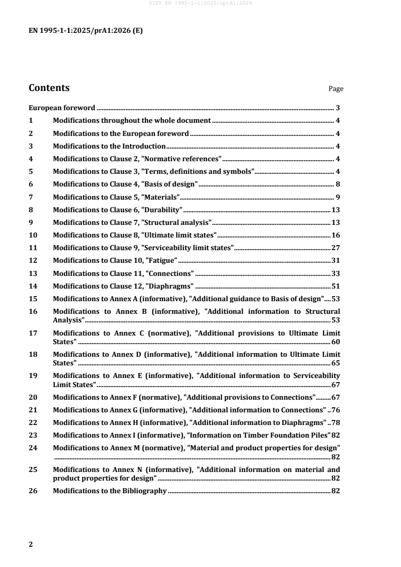
Contents Page
European foreword . 3
1 Modifications throughout the whole document . 4
2 Modifications to the European foreword . 4
3 Modifications to the Introduction . 4
4 Modifications to Clause 2, "Normative references" . 4
5 Modifications to Clause 3, "Terms, definitions and symbols" . 4
6 Modifications to Clause 4, "Basis of design" . 8
7 Modifications to Clause 5, "Materials" . 9
8 Modifications to Clause 6, "Durability" . 13
9 Modifications to Clause 7, "Structural analysis" . 13
10 Modifications to Clause 8, "Ultimate limit states" . 16
11 Modifications to Clause 9, "Serviceability limit states" . 27
12 Modifications to Clause 10, "Fatigue" . 31
13 Modifications to Clause 11, "Connections" . 33
14 Modifications to Clause 12, "Diaphragms" . 51
15 Modifications to Annex A (informative), "Additional guidance to Basis of design". 53
16 Modifications to Annex B (informative), "Additional information to Structural
Analysis" . 53
17 Modifications to Annex C (normative), "Additional provisions to Ultimate Limit
States" . 60
18 Modifications to Annex D (informative), "Additional information to Ultimate Limit
States" . 65
19 Modifications to Annex E (informative), "Additional information to Serviceability
Limit States" . 67
20 Modifications to Annex F (normative), "Additional provisions to Connections". 67
21 Modifications to Annex G (informative), "Additional information to Connections" . 76
22 Modifications to Annex H (informative), "Additional information to Diaphragms" . 78
23 Modifications to Annex I (informative), “Information on Timber Foundation Piles" 82
24 Modifications to Annex M (normative), "Material and product properties for design"
................................................................................................................................................................... 82
25 Modifications to Annex N (informative), "Additional information on material and
product properties for design" . 82
26 Modifications to the Bibliography . 82
European foreword
This document (EN 1995-1-1:2025/prA1:2026) has been prepared by Technical Committee CEN/TC 250
“Structural Eurocodes”, the secretariat of which is held by BSI. CEN/TC 250 is responsible for all
Structural Eurocodes and has been assigned responsibility for structural and geotechnical design matters
by CEN.
This document is currently submitted to the CEN Enquiry.
This document will amend EN 1995-1-1:2025.
NOTE Some modifications are purely editorial corrections to improve the quality of the document and these will
not be tagged in the consolidated publication, as noted after the modification.
The first generation of EN Eurocodes was published between 2002 and 2007. This document forms part
of the second generation of the Eurocodes, which have been prepared under Mandate M/515 issued to
CEN by the European Commission and the European Free Trade Association.
The Eurocodes have been drafted to be used in conjunction with relevant execution, material, product
and test standards, and to identify requirements for execution, materials, products and testing that are
relied upon by the Eurocodes.
The Eurocodes recognise the responsibility of each Member State and have safeguarded their right to
determine values related to regulatory safety matters at national level through the use of National
Annexes.
1 Modifications throughout the whole document
Replace “EN 1990:2023” with “EN 1990-1:2023+A1:2026”.
Replace “EN 1990” with “EN 1990-1” except for the reference to “EN 1990” in subclause 0.1.
Replace “EN 1991-1-1:2023” with “EN 1991-1-1:2025”.
Replace “FprEN 1993-1-4:2024” and “EN 1993-1-4:2024” with “EN 1993-1-4:2025”.
Replace “EN 1998-1-2:2023” with “EN 1998-1-2:2026”.
Replace “wood destroying” with “wood-destroying”.
Replace “TFD” with “framed diaphragm”.
2 Modifications to the European foreword
In the second bullet point, replace “inclusion of product groups” with “definition of groups consisting of
products”.
In the third bullet point, replace “inclusion” with “specification”.
In the fourth bullet point, replace “guidance” with “provisions”.
3 Modifications to the Introduction
In 0.1, after “— EN 1999 Eurocode 9 — Design of aluminium structures” add
“— EN 19100 Eurocode 10 — Design of glass structures”
“— New parts are under development, e.g. Eurocode for design of fibre-polymer composite structures
and for design of tensioned membrane structures”
In 0.2, in the third paragraph, replace “physical” by “single”. In the sixth paragraph, replace “CEN/TS
19103, Eurocode 5 — Design of timber structures — Structural design of timber-concrete composite
structures — Common rules and rules for buildings” with “EN 1995-1-3 , Eurocode 5 — Design of timber
structures — Part 1-3: Timber-concrete composite structures” and add footnote “ In development,
currently at Enquiry stage”.
In 0.2, last sentence add “EN” in front of “1995-2”.
In 0.3, delete “EN 1995-1-1 uses terms "should be considered" or “shall be considered”. In these cases, the
user should or shall, respectively, consider whether a requirement is relevant for its design or not.”
In 0.5, delete “F.3.2(2)” in the list of paragraphs for which a national choice is allowed.
4 Modifications to Clause 2, "Normative references"
Replace “EN 14080:2013” with “EN 14080”.
Replace “EN 1990:2023 , Eurocode — Basis of structural and geotechnical design” with “EN 1990-
1:2023+A1:2026, Eurocode — Basis of structural and geotechnical design — Part 1: New structures” and
1.
delete footnote
5 Modifications to Clause 3, "Terms, definitions and symbols"
Delete 3.1.1.3 and 3.1.1.5, then renumber 3.1.1.4 as 3.1.1.3.
In 3.1.3.1, replace “(3.1.3.15)” with “(3.1.3.16)”.
In 3.1.3.3, replace “the fibres” with “grain”.
In 3.1.3.4, add at the end of the definition “[SOURCE: EN 14080:2013, 3.15]”.
In 3.1.3.6, replace “bonded parallel to grain of the outermost veneers” with “where all panels or
laminations (3.1.3.8) consist”.
In 3.1.3.8, 3.1.3.10, 3.1.3.11 replace “lamellae” with “laminations”.
In 3.1.3.12, replace the definition with “composite consisting of veneers predominantly bonded parallel to
grain which may have crossband veneers” and delete the note to entry and source.
In Figure 3.2, replace the title with “Denomination of product sizes and orientation for LVL and GLVL”.
Replace the subfigures with the updated figures and the subfigure titles such that:
a) LVL stripe b) LVL plate c) GLVL beam
d) Flatwise e) Edgewise
Delete 3.1.3.15 and renumber the subsequent subclauses.
In 3.1.6, replace “ULS” with “Ultimate limit states (ULS)”.
In 3.1.7, replace “SLS” with “Serviceability limit states (SLS)”.
In 3.1.7.4, in the example, replace “CLT, LVL, nailed laminated or cross laminated timber-concrete
composite” with “flatwise oriented GL, CLT, LVL, GLVL and timber-concrete composite”.
In 3.1.9.9, replace “mortise” with “mortice”.
In 3.1.9.31, add “metal plate” after “part”, replace “plates with one part with integral projections” with
“formed” and replace “the second part to be connected and kept in place with dowel-type fasteners
(3.1.9.13)” with “plate connector (3.1.9.3)”.
In 3.1.10.3, add “, CLT (3.1.3.1), LVL (3.1.3.12) and GLVL (3.1.3.3)” before “connected”.
In 3.2.1, replace “footfall impulse” with “modal impulse due to footfall” for I .
mod,ef
In 3.2.2, add “ak” and its definition “clear distance between two ribs or the distance between a rib and the
end of the deck plate”.
In 3.2.2, add “a ” and its definition “distance between the locations where lateral deflection of the
r
compressive flange is prevented”.
In 3.2.2, add “b ” and its definition “minimum of the lamination width, the distance between the edge
l,min
and a groove and the spacing between grooves within a lamination”.
In 3.2.2, replace “inner thread diameter (of metric threaded fastener)” with “equivalent tensile stress
diameter” for d .
sp
In 3.2.2, replace “f ” with “f ” and “limit” with “threshold” in the corresponding definition.
1,lim 1,res
In 3.2.2, delete k and its definition.
c,90,CLT
In 3.2.2, replace “stress distribution” with “distribution of stresses” for k and k .
diam dis
In 3.2.2, add “k ” and its definition “frequency factor in the case of a double span floor on rigid supports”.
e,1
In 3.2.2, replace “k ” with “k ”.
k s
In 3.2.2, replace “K ” with “K ” and move to 3.2.1.
ka sa
In 3.2.2, replace “lamellae” with “laminations” for k .
mat
In 3.2.2, in the definition of k , replace “service conditions” with “environmental conditions in service”.
var
In 3.2.2, add “k ” and its definition “reduction factor for elevated moisture content”.
ω
In 3.2.2, delete “embedment length/” for l .
h
” with “l ”.
In 3.2.2, replace “lsea/street sea/road
In 3.2.2, replace “w ” with “w ”.
0 c
In 3.2.4, replace “gradient” with “angle” for α . Delete “correction” for κ. Delete “resistance” for γ .
(i) M,fat
In Table 3.1, replace “f ” with “f ” and “G ” with “G ”. Replace the figures with the updated figures.
v,xy xy v,xy xy
Symbols Verification of gross Verification Verification of gross cross-section
usually cross-section of net e.g. veneer based products (VB)
used in e.g. parallel laminated cross-
EN 1995-1-1 timber (PL) section
e.g. cross
laminated
timber
c
(CLT)
for the
considered
direction
e d e d
fm, sm,flat fm fm fm,0 or fm,0,flat with sm,flat fm,90 or fm,90,flat
e d e d
f , f , s f f and f f or f with s f or f
v r v,flat v v r r,0 v,0,flat v,flat r,90 v,90,flat
E E E E E
0 0 m,0 m,90
G G and G G G
G, G , G r r,0 r,90
v r
for the
considered
direction
d d
f , s f f f with s or f f or f
m m m,edge m,0,edge p,0 m,90,edge p,90
fv and/or fv fxy and
fv,0,edge or fv,0 fv,90,edge or fv,90
ftor,node ftor,node
E E E E or E E or E
0 0 m,0 p,0 m,90 p,90
G, Gv, G0, G
Gxy Gv or Gv,0 Gv or Gv,90
G0,edge, Gp
for the
considered
direction
d f
ft,0 ft,0 ft,0 ft,0 with s or st ft,90,edge or ft,90
Et,0 Et,0 Et,0 Et,0 Et,90
d
f f f f or f
t,90 t,90 t,90 t,90 t,90,flat
E E E E
90 90 90 90
Symbols Verification of gross Verification Verification of gross cross-section
usually cross-section of net e.g. veneer based products (VB)
used in e.g. parallel laminated cross-
EN 1995-1-1 timber (PL) section
e.g. cross
laminated
timber
c
(CLT)
for the
considered
direction
d
fc,0 fc,0 fc,0 fc,0 fc,90,edge or fc,90
d
Ec,0 Ec,0 Ec,0 Ec,0 Ec,90,edge or Ec,90
fc,90 fc,90 fc,90 fc,90 or fc,90,flat
E90 E90 E90 E90 or E90,flat
a
This table is based on symbols given in the different product standards.
b
If alternative symbols are given in this table (indicated by “or”), they refer to different products or different directions.
In the case of “and” both symbols are typically needed for one design situation.
c
Layer properties for cross laminated timber (CLT), if any, are referring to the element’s directions x and y. For the
design with reference to the layers these indices are omitted (as not required). The properties refer to grain direction
of the considered layer and symbols are in accordance with EN 338.
d
For laminated veneer lumber (LVL) and Glued laminated veneer lumber (GLVL).
e
Only for glued laminated veneer lumber (GLVL).
f
Only for hardwood glued laminated veneer lumber (GLVL).
6 Modifications to Clause 4, "Basis of design"
In 4.3.1.1(2), replace “In special cases, project” with “Project”.
In 4.3.1.2(1), in the second bullet point, replace “restricted” with “obstructed”.
In 4.3.1.2(2), in NOTE 4, replace “NOTE 4” with “NOTE”.
In Table 4.1, in row 2 add ‘differential settlements’ after ‘prestress’, in row 4 add ‘moisture variations’ after
‘snow’ and in row 5 add ‘traffic load, temperature’ after ‘wind’ such that:
Accumulated
Load-duration class Examples of loading (NDP)
duration of characteristic load
self-weight, prestress, differential
Permanent more than 10 years
settlements
Long-term 6 months – 10 years storage
imposed floor load, snow, moisture
Medium-term 1 week – 6 months
variations
snow, wind, traffic load,
Short-term less than one week
temperature
Instantaneous usually less than one minute wind, impact, seismic action
NOTE The load-duration classes are characterised by the effect of a constant load acting for a certain period during
the design service life of the structure.
In Table 4.2, in NOTE 1, add “but under certain regional and seasonal conditions it may be lower” after “7
% - 10 %” and in footnote d, add “, glued laminated veneer lumber” after “laminated veneer lumber”.
In 4.3.2(1), in the third bullet point, replace “Member State” with “country”.
In 4.4.1(5), in the key for k , replace “of a material accounting for the relevant service class” with “, see
def
5.2.2;”
In 4.4.2(1), replace “requirements” with “recommendations”.
Replace Figure 4.2 with the updated figure.
In 4.5.1(2), in the note, delete “resistance”.
γ ” with “γ ”. In the note, replace “γ ” with “γ ” and “γ ” with “γ ”.
In 4.5.2(2), replace “ M,fat R,fat M,fat R,fat M R
In Table 4.3, remove superfluous footnote a from the third column of the first row 1. Add indentation before
“Cross laminated timber” and “Multi-layered solid wood panel”.
In Table 4.4, in row 5, delete “based on an (semi-)empirical analysis”. In NOTE 2, add “γ and γ ” after
M,s P
“factors”.
7 Modifications to Clause 5, "Materials"
In 5.1.2(1), replace “based on” with “determined assuming”.
In 5.1.3(1), add “in 3.2.6” after “defined”.
Replace the title of Table 5.1 with “Reference standards and EADs for products and materials”.
In Table 5.2, replace the title with “Reference standards and EADs for fasteners and connectors”. In row 9,
replace “Lag screw” with “Coach screw”. In penultimate row add “, etc.” between “device” and the closing
bracket.
In Table 5.3, replace the whole NOTE 2 with “NOTE 2 For the choice of adhesive types, additional national
specific application rules for products can apply.”
In 5.2.1(3), replace “and GL” with “, GL and BGL”.
In 5.2.1 there are two paragraphs numbered (3), renumber the second instance of (3) and the subsequent
paragraph.
In Table 5.4, delete the two rows for “Connections with bonded-in rods”. In the first row for “Solid wood
panel (SWP)”, replace “or SWP/2S” with “SWP/1S, SWP/2S or SWP/3S”. In the second row for “Solid wood
panel (SWP)”, add “or SWP/3S” after “SWP/2S”.
In 5.2.2(1), delete ", see 4.4”.
In 5.2.2(4), replace “When a connection with mechanical fasteners is formed between steel plate” with
“For mechanical connections between a metal part” and replace “deflection” with “deformation”.
In Table 5.5, in the second row for “Single layer solid wood panel (SWP-P)”, add “, SWP/3S” after “SWP/2S”,
in the second row for “Multi-layered solid wood panel (SWP-C)”, add “, SWP/3S” after “SWP/2S”, for
“Fibreboard, medium (MB)” and “MBH.HLS1, MBH.HLS2”, replace “4,00” with ”—” in the fourth column
and for “Softboard (SB)”, replace “3,00” with "6,50” in the third column and ”—” with “10,00” in the fourth
column such that:
Single layer solid wood panel (SWP-P) SWP/1S 0,60 — —
SWP/2S, SWP/3S 0,60 0,80 —
Multi-layered solid wood panel SWP/1S 0,80 — —
(SWP-C)
SWP/2S, SWP/3S 0,80 1,00 —
..
Fibreboard, medium (MB) MBH.LA1, MBH.LA2 3,00 — —
MBH.HLS1, MBH.HLS2 3,00 — —
Softboard (SB) 6,50 10,0 —
In 5.3(1), add “by applying the relevant size modification factor k according to Formula (5.3)” after
h,i
“considered”. Add the following note “NOTE The size effect on shear strength is included in the
modification factor for shear strength k given in 8.1.11.1(3).”
v
In 5.3(2), replace the whole paragraph with “For all other strengths any size effects are considered in the
relevant design Formulae, see 8.3.4.1 and 8.3.6.1.”
In 5.3(3), add “size” between “The” and “modification”. In Formula (5.3), add index “,i" after the first index
to each parameter of the formula and its key such that:
s,i
k ≤ k = (a /a ) ≤ k
h,i h,i,min ref,i i h,i,max
and “k ”, “a ”, “a”, “s” and “k ” are respectively replaced with “k ”, “a ”, “a ”, “s ” and “k ”. Add
h,min ref h,max h,i,min ref,i i i h,i,max
“i is m, t or v for bending, tension or shear, respectively;” as the first key.
Delete 5.3(4), 5.3(5), 5.3(6), 5.3(7) but retain Table 5.6 that will now show after the NOTE in 5.3(3).
In Table 5.6, replace “strength” with “size”, “k ” with “k " and “formula” with “Formula” in the title of the
h h,i
table. Replace Table 5.6 with:
Strength to be modified a a s k k
i ref,i i h,i,max h,i,min
mm mm - - -
a a
Structural timber (ST) , Finger jointed timber (FST) ,
a
Glued solid timber (GST)
Bending parallel to grain Dimension perpendicular 150
to bending axis
Tension parallel to grain Larger dimension of 150
0,2 1,3 1,0
cross-section
Shear Dimension perpendicular 150
to bending axis
b
Glued-laminated timber (GL)
Bending parallel to grain Dimension perpendicular 600 0,04 - -
to bending axis
Shear Dimension perpendicular 600 0,1 1,1 0,9
to bending axis
Laminated veneer lumber (LVL and GLVL)
c c
Bending parallel to grain, Dimension perpendicular 300 0,15 1,2 -
edgewise to bending axis
Bending parallel to grain, Value according to applicable European technical product
flatwise, only GLVL specification
c d
Tension parallel to grain Length of member 3000 - 1,1 -
Shear, only GLVL Value according to applicable European technical product
specification
a 3
For characteristic timber density ρ ≤ 700 kg/m .
k
b
Modification factor k only applicable for glued laminated timber whose glue lines are in same
h
direction as bending axis.
c
Value according to applicable European technical product specification.
d
s is taken as half of the value for bending.
In 5.4.2(1), replace whole paragraph with “For in-plane shear verifications of the net-cross-section, the
characteristic value of in-plane shear strength f should be taken as 5,5 N/mm unless a different
xy,k
value is declared.”
In 5.4.2(2), add “value of” between “characteristic” and “torsional”, replace “lamellae” with “laminations”
and delete "f =” between “taken as” and “2,5”.
tor,node,d
In 5.4.2(4), replace “t ” with “t”.
CLT
In 5.4.2, add the following new paragraphs and new Formula (5.6) - no updating of references or
renumbering of formulae required:
“(4) The characteristic value of bending strength in plane f should be taken as the characteristic
m,edge,k
bending strength of the laminations f unless a different value is declared.”
m,l,k
“(7) For in-plane shear verifications of the gross cross-section, the mean in-plane shear modulus G
xy,mean
should be determined in accordance with Formula (5.6) unless a different value is declared.
2)
1,2
𝑡𝑡
l,max
𝐺𝐺 = min.�1+2,6� � (5.6)
xy,mean
𝑏𝑏
l,min
where
b is the minimum lamination width, which is either the width of the lamination or the distance
l,min
between the edge and a groove or spacing between grooves within the lamination;
t is the maximum thickness of a layer.”
l,max
Delete the note in 5.5(2).
Replace Table 5.8 with:
Shrinkage/swelling value, in %, for an
average
difference of material moisture content of
Material
1 %
Perpendicular to plane
In-plane of panel
of panel
Cross laminated timber (CLT) and multi-layered solid
a
0,24 0,02 – 0,04
wood panel (SWP-C)
Laminated veneer lumber with parallel veneers (LVL-
P), glued laminated veneer lumber with parallel veneers
(GLVL-P)
b
- parallel to grain 0,32; (0,45 ) 0,01
b b
- perpendicular to grain (parallel to faces) 0,32; (0,45 ) 0,32; (0,40 )
Laminated veneer lumber with crossband veneers
(LVL-C), glued laminated veneer lumber with crossband
veneers (GLVL-C)
b
- parallel to grain of outer veneers 0,32; (0,45 ) 0,01
- perpendicular to grain of outer veneers (parallel to
b
0,32; (0,45 ) 0,03
faces)
Plywood (PW) 0,32 0,02
Oriented strand board (OSB),
- types OSB/2 and OSB/3 0,70 0,03
- type OSB/4 0,50 0,015
Resin-bonded particleboard (RPB), fibreboard (HB +
0,70 0,035
MB)
Shrinkage/swelling value, in %, for an
average
difference of material moisture content of
Material
1 %
Perpendicular to plane
In-plane of panel
of panel
Cement-bonded particleboard (CPB) 0,05 0,03
a
Swelling and shrinkage values in-plane depend on the layup. For typical layups, the lower value refers to the x-
direction and the higher to the y-direction.
b
Laminated veneer lumber (LVL) or Glued laminated veneer lumber (GLVL) from European beech wood.
8 Modifications to Clause 6, "Durability"
In 6.2.2.1(1), add “The maximum permitted moisture content during installation should be 20 % for
timber products and 18 % for wood-based panel products, products made of LVL or GLVL.” at the end of
the paragraph. In NOTE 1, replace “of maximum permitted moisture content are for timber products 20
% and for wood-based panel products or products made of LVL and GLVL 18 %” with “given in 6.2.2.1(1)
apply unless”.
In 6.2.2.1(3), replace “Precipitation” with “Where possible, precipitation” and delete “as far as possible”.
In the note, add “α” between “rainfall” and “depends”.
In 6.3.1(2), replace “necessary” with “required”.
In 6.3.1(4), add “required for a 50-year design service life of the structure” at the end of the sentence. Add
“NOTE Table 6.2 can also be used as a basis for assessments for design service life other than 50 years,
for galvanized products.”
In 6.3.3.1(1), replace the paragraph with “For a carbon steel fastener or connector, the resistance to
corrosion resulting from timber conditions and atmospheric exposure, should be classified using the TR-
category and the CR-category, respectively.” but keep the notes.
In Table 6.1, replace index “street” with “road”. Replace definition of L with “indicates distance from the
sea
sea. The actual exposure depends on the prevailing wind direction and the topography of the coast to
saltwater seas.”
9 Modifications to Clause 7, "Structural analysis"
In 7.1(1), replace “for models” with “models for”.
In 7.1(2), add “, e.g. duration of load,” between “materials” and “creep” in the fourth bullet point. Add a
bullet point to the end of the list “— behaviour of the connections on the distribution of internal forces and
moments within a structure and on the overall deformations of the structure.” Replace the period with a
semicolon for the eleventh bullet point.
In 7.2.2(1), add “, for member buckling verification see 8.2.2.1(1)” to the end of the first bullet point.
In 7.2.3(2), replace “0” with “zero”. Add “be” between “may” and “taken”. Delete the note.
In 7.2.4(3), add “, if relevant” to the end of the sentence.
In Figure 7.2, replace all the subfigures with the updated figures.
a) Axonmetry
b) Equivalent twist imperfection of
the cross-section at the fork support
and at midspan (view B-B) c) Equivalent bow imperfection of a beam (view A-A)
In Figure 7.3, replace all the subfigures with the updated figures.
a) System
b) Symmetric equivalent imperfections
c) Asymmetric equivalent imperfections
Delete “4 Beam” from the key. Delete “maximum” in the key for e. Replace “α” with “β” in the key. Replace
“l ” with “l ” in the key. Replace “sway of a member at a fork support” with “twist imperfection at the
i ef,i
support” in the key for 𝜃𝜃 . Replace “total rotation of the member” with “equivalent twist imperfection of
sup
the beam” in the key for 𝜃𝜃 .
twist
In 7.4.1(2), delete “maximum” in the sentence preceding the formula. In Formula (7.2), delete “= ε l”. Delete
“ε is the dimensionless form of the imperfection” and replace the semicolon with a period after the
description for l.
In 7.4.1(3), in the note, add “, as the equivalent bow imperfection given in this document represents a 95%
quantile value, whereby the bow imperfection in the product standards is an absolute limit.” to the end of
the sentence.
In 7.4.1(6), replace “(see Formula (7.3))” with “according to Formula (7.3)” in the key for θ . Replace “(see
sup
Formula (7.4))” with “according to Formula (7.4)” in the key for θ .
twist
In 7.4.1(7), delete “maximum” in the sentence preceding the formula. Delete “maximum” in the key for e.
Replace “twist” with “equivalent twist imperfection” in the key for θ .
twist
In 7.4.1(9), replace “The” with “For the design of bracings the” in the sentence preceding the formula.
Replace “Figure 7.4” with “Figure B.3” in the sentence preceding the formula. In the key, replace “ϕ” with
text instead of an equation. Delete “maximum” in the key for e.
In 7.4.2(2), add “, see Figure 7.4” to the end of the sentence.
In 7.4.2(3), delete “, see Figure 7.4”.
In Figure 7.4, replace subfigure d) with the updated figure.
Add “design” before “normal” in the key for N . Replace “q” with “q ” in the key. Add “design” before
Ed d
“equivalent” in the key for q. Delete “maximum” in the key for e. Add “M design bending moment” to the
Ed
key.
In 7.5.1(1), in the note, replace “B.3.2” with “B.3.3”.
In 7.5.2(1), delete “a” after “A substructure such”.
Replace Figure 7.5 with the updated figure.
In 7.5.2(3), replace “Formula (7.3)” with “Formula (7.10)” in the key for k .
sim
In Table 7.1, add “k ” after “Constant” in the header row and replace “k ” with “Q ” in the header row.
Q,B Q,B i,d
In 7.5.2(4), delete “maximum” in the key for e .
y
In 7.5.2(5), add “maximal” after “is the” in the key for M .
y,d
In 7.5.2(6), delete “maximum” in the key for e .
y
In 7.6(3), replace “The” with “In the absence of specific information for the framing structure,”.
10 Modifications to Clause 8, "Ultimate limit states"
In 8.1.1(3), replace “7.2.3” with “7.2.4”.
In 8.1.1, add new paragraph (4): “The effect of member size shall be taken into account where relevant,
see 5.3.”
Delete 8.1.3(1).
In 8.1.4, add “in-plane” between “grain” and “for” in the title.
In 8.1.4(1), delete “in-plane” between “For” and “design” and add “in-plane” between “grain” and “σ ".
t,α,d
Replace the whole Formula (8.2) with:
𝑓𝑓
t,0,d
𝜎𝜎 ≤ for PW, SWP-C and OSB
t,α,d 𝑓𝑓
t,0,d
2 2
sin 𝛼𝛼+ cos 𝛼𝛼
𝑓𝑓
t,90,d
In Formula (8.3), replace “f ” with “f ”, delete the multiplication sign between “sin α” and “cos α" and
v,d v,0,edge,d
replace “LVL and GLVL" with “LVL-C and GLVL-C” such that:
𝑓𝑓
t,0,d
𝜎𝜎 ≤ for LVL-C and GLVL-C (8.3)
t,α,d 𝑓𝑓 𝑓𝑓
t,0,d t,0,d
2 2
sin 𝛼𝛼+ sin𝛼𝛼 cos𝛼𝛼 + cos 𝛼𝛼
𝑓𝑓 𝑓𝑓
t,90,d v,0,edge,d
In 8.1.4(1), in the key for Formula (8.3), replace “f ” with “f ” and add “edgewise parallel to grain”
v,d v,0,edge,d
after “strength”. .
In 8.1.4(1), add the following note after the key: "NOTE For CLT, forces at an angle to grain are decomposed
and verified in x and y main in-plane directions."
In Table 8.1, replace NOTE 3 with “Provided bulging at the area of applied load is prevented, values of k
mat
higher than these indicated can apply.", NOTE 5 with "Linear interpolation between Cases A and B and
between Cases B and C can be used to determine the strain level of other values of kmat" and footnote a
with: “Case A covers most common design situations and corresponding strain values indicate the on-set
of yielding. It applies when deformations would otherwise result in member or system instability or cause
unacceptable damage to other components, e.g. for structural timber where h > 5b; where h is the
member depth and b the width. The strain values indicate the on-set of yielding.” such that:
NOTE 1 For the calculation of deformations in serviceability limit state design situations, see 9.4.
NOTE 2 The depth to width ratio restriction in Case A (see below) is to prevent premature rolling shear failure.
NOTE 3 Provided bulging at the area of applied load is prevented, values of kmat higher than these indicated can
apply.
NOTE 4 Further guidance on choice of case can be given in the National Annex.
NOTE 5 Linear interpolation between Cases A and B and between Cases B and C can be used to determine the
strain level of other values of kmat.
a
Case A covers most common design situations and corresponding strain values indicate the on-set of yielding.
It applies when deformations would otherwise result in member or system instability or cause unacceptable
damage to other components, e.g. for structural timber where h > 5b; where h is the member depth and b the width.
The strain values indicate the on-set of yielding.
b
Case B applies when deformation has no significant effect on member or system stability.
c
Case C applies when deformation has no significant effect on member stability and failure of the member
does not lead to failure of the whole structure or parts of it. Such cases include members that are continuously
supported and for which the width b ≥ h, or plate or beam supports where local indentation will not lead to failure
of the whole structure or parts of it, e.g. due to force redistribution to adjacent members. This also applies to CLT.
d
Strain is the ratio of the total deformation and the effective depth hef. For continuously supported members (see
Figure 8.2) h = h. The strain values are approximate magnitude values.
ef
In 8.1.6.1(5), replace “A ” with “A” and replace “can” with “may”. Replace “b ” with “b ” and “l ” with
c,90 90,c c,90 90,c
“l ” in Formula (8.9) and its key. In the key for b , add "or applied force” between "support” and
c,90 c,90
"perpendicular" and add “, see Figure 8.2 to 8.4" at end of sentence. In the key for l , add between
c,90
"support” and “parallel" and replace “and Figure 8.3” with “to 8.4”.
In 8.1.6.1(6), replace “gradient α” with “angle α”. Add "(see Figure 8.2 to 8.4)" between “angle α” and “in
accordance".
In Table 8.2, replace “gradient α” with “angle α” in title and header row. Add “, and” between “LVL-C” and
“GLVL-C” in first column of the last row. Delete footnote a after “Perpendicular to grain” in the last column
of the header row.
In Figure 8.2, replace both subfigures with the updated figures.
a) Member depth h ≤ = h
ef
b) Member depth h > h
ef
Add the following notes " NOTE 1 Values for stress spreading angles are given in Table 8.2” and " NOTE 2
Figure illustrates a situation where the width of the applied force b equals the width b of the
c,90
member." Replace "≤" with "=" in the title for subfigure a).
In Figure 8.3, replace the figure with the updated figure.
Replace “gradient” with “angle” in the title. In the note, replace “For” with “Values for” and “gradient, see”
with “angles are given in” and add a period to the end of the sentence. Add the following note “NOTE 2
Figure illustrates a situation where the width of the applied force and width of the support b equal
c,90
the width b of the member." and renumber the existing note “NOTE 1”.
In Figure 8.4, replace all the subfigures with the updated figures.
b) At local supports
a) At continuous supports
d) For forces at locally loaded locations
c) At contact areas at both opposite sides
having different size and position
Replace “gradient” with “angle” in title. Delete the empty row before subfigure titles c) and d). In the note,
replace “For” with “Values for” and “gradients” with “angles”, delete superfluous space before “Table 8.2”
and add a period to the end of the sentence.
In 8.1.6.2(1), replace “softwood members made from” with “members from softwood products”.
In 8.1.6.2(2), replace “of 90°” with “(90°)”.
In 8.1.6.2(5), replace “d” with “d”. In Formula (8.13), add “; l ” to the second and third term of the formula
90,c
such that:
⁄ ⁄
𝑙𝑙 =𝑙𝑙 + min�𝑙𝑙 ; 30;𝑙𝑙 2; 𝑙𝑙 � + min�30;𝑙𝑙 2; 𝑙𝑙 �
1,ef 90,c e s 90,c s 90,c
In Formula (8.14), add “; l ” to the second and third term of the formula such that:
90,c
⁄ ⁄
𝑙𝑙 =𝑙𝑙 + min�30;𝑙𝑙 2; 𝑙𝑙 � + min�30;𝑙𝑙 2; 𝑙𝑙 �
1,ef 90,c s 90,c s 90,c
Replace “For” with “Due to the cutting of wood fibres, for angles” in the key for l . Delete “fully threaded”
1,ef
in the key for n, n and n . Delete “arranged” in the key for n and n .
0 90 0 90
In 8.1.6.2(6), replace “GST and FST” with “FST and GST”. In the note, add “stress distribution for reinforced
supports is different compared to unreinforced supports. Consequently, the” between “The” and
“reinforcement” in the first sentence. In the note, replace “of the” with “over the entire” in the last sentence.
In 8.1.6.2(10), in the note, replace "equation” with “Formula”. Delete “close or”.
In Figure 8.5, replace all the subfigures with the updated figures.
a) Discrete end support with reinforcement b) Intermediate support (of inclined member) with
reinforcement
c) Discrete support with reinforcement d) Overlapping reinforcement
Add “maximum” between “recommended” and “spacing” in the key for 6.
In 8.1.6.2(11), replace “φ” with “φ ” in Formula (8.18) and its key. Add “relative” between “the” and
max,k
“deformation” in the key for Δw. Replace “combination” with “combinations” in the key for φ .
max,k
In Figure 8.6, replace the figure with the updated figure.
In 8.1.7, assign paragraphs (1) to (3) to new subclause “8.1.7.1” with title "General". Add new subclause
“8.1.7.2” with title "Compression at an angle to grain in-plane for timber products with cross layers".
In 8.1.7.1(2), add “Except for compression at an angle to grain in-plane in accordance with 8.1.7.2,” before
“for design compressive stress”. In Formula (8.19), delete "for SL and PL”. Delete Formula (8.20) and delete
"f is the design shear” from the key.
v,d
In 8.1.7.2(1), add new paragraph text as follows: “For design compressive stress at an angle α to grain in-
plane σ in members made of PW, LVL-C, GLVL-C, SWP-C and OSB, the following shall be satisfied: ".
c,α,d
Add Formulae (8.20) and (8.21) and their key and new NOTE as follows, and renumber subsequent figures
and their references in the text:
𝑓𝑓
c,0,d
“𝜎𝜎 ≤ for PW, SWP-C and OSB (8.20)
c,α,d
𝑓𝑓
c,0,d
2 2
sin 𝛼𝛼+ cos 𝛼𝛼
𝑓𝑓
c,90,d
𝑓𝑓
c,0,d
𝜎𝜎 ≤ for LVL-C and GLVL-C (8.21)
c,α,d 𝑓𝑓 𝑓𝑓
c,0,d c,0,d
2 2
sin 𝛼𝛼+ sin𝛼𝛼 cos𝛼𝛼 + cos 𝛼𝛼
𝑓𝑓 𝑓𝑓
c,90,d v,0,edge,d
where
f is the design compressive strength parallel to grain;
c,0,d
f is the design compressive strength perpendicular to grain in-plane;
c,90,d
f is the design shear strength edgewise parallel to grain.
v.0,edge,d
NOTE For CLT, forces at an angle to grain are decomposed and verified in x and y main in-plane directions.”
In 8.1.8.2(1), delete the brackets around “α” (two occurrences) in Formula (8.23). Replace “degree” with
“degrees” in the key for α. Add the following note "NOTE For CLT, forces at an angle to grain are
decomposed and verified in x and y main in-plane directions."
In 8.1.8.2(2), replace "EN 14374" with "the technical specification".
In 8.1.10(1), replace “strength” with “stress” in the key for p.
In 8.1.11.1(1), in the note, replace “Formula (8.28)” with “Formula (8.29)”.
In 8.1.11.1(3), add “softwood products” between “for” and “ST” and between “for” and “GL” in Formula
(8.31). In the key for k , replace “service conditions” with “environmental conditions in service”. Add the
var
following note “NOTE 1 Values of f for hardwood products ST, FST, GST, GL or BGL can be specified by
v,ref,k
a relevant authority or, where not specified, agreed for a specific project by appropriate parties.” and
renumber existing NOTE as “NOTE 2”.
In 8.1.11.1(4), replace “service conditions k ” with “environmental conditions in service k ”. Replace
var var
“service conditions of 4.3.1.4” with “environmental conditions preventing large moisture content
variations”.
In 8.1.11.1(5), replace period with comma as decimal separator.
In 8.1.11.1(7), replace “made from” with “products”.
In 8.1.11.1(9), delete two instances of “<2>”.
In 8.1.11.1(10), in the note, replace “edges” with “upper and lower faces”.
In Figure 8.7, renumber key 1 and 2 respectively as 2 and 3 and add key 1 as “1 location for calculating shear
force”.
In 8.1.11.2(2), replace “Formula (8.27)” with “Formula (8.28)”.
In 8.1.11.2(3), replace “the design shear stress in-plane τ of the effective net cross-section” with “the
v,xy/yx,d
greater of the design shear stresses in-plane τ or τ of the respective effective net gross-section" and
xy,d yx,d
replace "τ " with "max�𝜏𝜏 ; 𝜏𝜏 �" in Formula (8.33). Replace “b ” and “t ” with “b ” and “t ” in
v,xy/yx,d l l l,min l,max
xy,d yx,d
the first sentence, in Formula (8.33) and in the key.
In 8.1.12(1), in NOTE 1, replace “Table 4.1” with “Table 3.1”.
In 8.1.13(1), in the note, replace “Formula (8.35)” with “Formula (8.36)”.
In 8.1.14(2), replace “stress distribution” with “distribution of stresses”.
In Figure 8.8, replace subfigure b) with the updated figure.
Replace "axis" with "direction" in key for v; w.
In 8.2.2.2(1), delete “. In fire design situations, the design compressive strength should be used instead”
from the key for f .
c,0,k
In Table 8.2, delete footnote c and its referen
...