

EN 1870-17:2012
(Main)Safety of woodworking machines - Circular sawing machines - Part 17: Manual horizontal cutting cross-cut sawing machines with one saw unit (radial arm saws)
- Abstract
This European Standard specifies all significant hazards, hazardous situation and events as listed in Clause 4, relevant to stationary and displaceable manual horizontal cutting cross-cut circular sawing machines with one saw unit (manual radial arm saws), hereinafter referred to as "machines", designed to cut solid wood, chipboard, fibreboard, plywood and also these materials if they are covered with plastic edging and/or plastic laminates, when they are used as intended and under the conditions foreseen by the manufacturer including reasonably foreseeable misuse.
NOTE 1 For the definition of stationary and displaceable machine, see 3.2.3 and 3.2.4.
The requirements of this document apply to all machines whatever their method of control e.g. electromechanical and/or electronic.
This document does not apply to:
a) machines set up on a bench or a table similar to a bench, which are intended to carry out work in a stationary position, capable of being lifted by one person by hand; the bench can also be an integrated part of the machine if it consists of hinged legs which can be extended down;
NOTE 2 Transportable motor-operated electrical tools are dealt with in EN 61029-1:2009 together with
IEC 61029-2-2:1993.
b) machines fitted with hydraulically powered machine actuators;
c) machines fitted with powered work-piece positioning;
d) machines fitted with the facility for either ripping, milling (including trenching and grooving), sanding and/or drilling;
e) machines equipped with more than one saw spindle speed;
NOTE 3 A standard to cover machines that can be used for ripping and moulding will be considered at the next revision.
NOTE 4 Semi-automatic and automatic horizontal cutting cross-cut circular sawing machines with one saw unit (radial arm saws) are dealt with in EN 1870-11:2003+A1:2009.
f) machines with integrated feed.
This document is not applicable to manual horizontal cutting cross-cut circular sawing machines with one saw unit (manual radial arm saws) which are manufactured before the date of its publication as EN.
- Status
- Withdrawn
- Publication Date
- 16-Oct-2012
- Withdrawal Date
- 06-Oct-2026
- Technical Committee
- CEN/TC 142 - Woodworking machines - Safety
- Drafting Committee
- CEN/TC 142/WG 4 - Circular sawing machines
- Current Stage
- 9960 - Withdrawal effective - Withdrawal
- Start Date
- 08-Apr-2015
- Completion Date
- 07-Oct-2026
- Directive
- 2006/42/EC - Directive 2006/42/EC of the European Parliament and of the Council of 17 May 2006 on machinery, and amending Directive 95/16/EC (recast)OJ Ref: C, C 054, C 92 OJ Date: 13-Feb-2015

Relations
- Effective Date
- 08-Jun-2022
- Effective Date
- 18-Jan-2023
- Effective Date
- 25-Aug-2026
- Effective Date
- 25-Aug-2026
- Effective Date
- 25-Aug-2026
- Effective Date
- 09-Feb-2026
- Effective Date
- 09-Feb-2026
- Refers
EN 60825-1:2007 - Safety of laser products - Part 1: Equipment classification and requirements - Effective Date
- 09-Feb-2026
- Effective Date
- 09-Feb-2026
- Effective Date
- 09-Feb-2026
- Effective Date
- 09-Feb-2026
- Effective Date
- 09-Feb-2026
- Effective Date
- 28-Jan-2026
- Effective Date
- 28-Jan-2026
- Effective Date
- 28-Jan-2026
Get Certified
Connect with accredited certification bodies for this standard

Gozdarski inštitut Slovenije
Slovenian Forestry Institute. Forest management certification support, timber testing.
Sponsored listings
Frequently Asked Questions
EN 1870-17:2012 is a standard published by the European Committee for Standardization (CEN). Its full title is "Safety of woodworking machines - Circular sawing machines - Part 17: Manual horizontal cutting cross-cut sawing machines with one saw unit (radial arm saws)". This standard covers: This European Standard specifies all significant hazards, hazardous situation and events as listed in Clause 4, relevant to stationary and displaceable manual horizontal cutting cross-cut circular sawing machines with one saw unit (manual radial arm saws), hereinafter referred to as "machines", designed to cut solid wood, chipboard, fibreboard, plywood and also these materials if they are covered with plastic edging and/or plastic laminates, when they are used as intended and under the conditions foreseen by the manufacturer including reasonably foreseeable misuse. NOTE 1 For the definition of stationary and displaceable machine, see 3.2.3 and 3.2.4. The requirements of this document apply to all machines whatever their method of control e.g. electromechanical and/or electronic. This document does not apply to: a) machines set up on a bench or a table similar to a bench, which are intended to carry out work in a stationary position, capable of being lifted by one person by hand; the bench can also be an integrated part of the machine if it consists of hinged legs which can be extended down; NOTE 2 Transportable motor-operated electrical tools are dealt with in EN 61029-1:2009 together with IEC 61029-2-2:1993. b) machines fitted with hydraulically powered machine actuators; c) machines fitted with powered work-piece positioning; d) machines fitted with the facility for either ripping, milling (including trenching and grooving), sanding and/or drilling; e) machines equipped with more than one saw spindle speed; NOTE 3 A standard to cover machines that can be used for ripping and moulding will be considered at the next revision. NOTE 4 Semi-automatic and automatic horizontal cutting cross-cut circular sawing machines with one saw unit (radial arm saws) are dealt with in EN 1870-11:2003+A1:2009. f) machines with integrated feed. This document is not applicable to manual horizontal cutting cross-cut circular sawing machines with one saw unit (manual radial arm saws) which are manufactured before the date of its publication as EN.
This European Standard specifies all significant hazards, hazardous situation and events as listed in Clause 4, relevant to stationary and displaceable manual horizontal cutting cross-cut circular sawing machines with one saw unit (manual radial arm saws), hereinafter referred to as "machines", designed to cut solid wood, chipboard, fibreboard, plywood and also these materials if they are covered with plastic edging and/or plastic laminates, when they are used as intended and under the conditions foreseen by the manufacturer including reasonably foreseeable misuse. NOTE 1 For the definition of stationary and displaceable machine, see 3.2.3 and 3.2.4. The requirements of this document apply to all machines whatever their method of control e.g. electromechanical and/or electronic. This document does not apply to: a) machines set up on a bench or a table similar to a bench, which are intended to carry out work in a stationary position, capable of being lifted by one person by hand; the bench can also be an integrated part of the machine if it consists of hinged legs which can be extended down; NOTE 2 Transportable motor-operated electrical tools are dealt with in EN 61029-1:2009 together with IEC 61029-2-2:1993. b) machines fitted with hydraulically powered machine actuators; c) machines fitted with powered work-piece positioning; d) machines fitted with the facility for either ripping, milling (including trenching and grooving), sanding and/or drilling; e) machines equipped with more than one saw spindle speed; NOTE 3 A standard to cover machines that can be used for ripping and moulding will be considered at the next revision. NOTE 4 Semi-automatic and automatic horizontal cutting cross-cut circular sawing machines with one saw unit (radial arm saws) are dealt with in EN 1870-11:2003+A1:2009. f) machines with integrated feed. This document is not applicable to manual horizontal cutting cross-cut circular sawing machines with one saw unit (manual radial arm saws) which are manufactured before the date of its publication as EN.
EN 1870-17:2012 is classified under the following ICS (International Classification for Standards) categories: 79.120.10 - Woodworking machines. The ICS classification helps identify the subject area and facilitates finding related standards.
EN 1870-17:2012 has the following relationships with other standards: It is inter standard links to EN 1870-17:2007+A2:2009, EN 1870-17:2012+A1:2015, ISO 7490:1990, ISO 8598:1996, ISO 7960:1995, EN 61310-1:2008, EN 60439-1:1999, EN 60825-1:2007, HD 22.4 S4:2004, EN 61800-5-2:2007, EN 60529:1991, EN 50370-1:2005, EN 1088:1995+A2:2008, EN ISO 5511:1996, EN ISO 11202:2010. Understanding these relationships helps ensure you are using the most current and applicable version of the standard.
EN 1870-17:2012 is associated with the following European legislation: EU Directives/Regulations: 2006/42/EC; Standardization Mandates: M/396. When a standard is cited in the Official Journal of the European Union, products manufactured in conformity with it benefit from a presumption of conformity with the essential requirements of the corresponding EU directive or regulation.
EN 1870-17:2012 is available in PDF format for immediate download after purchase. The document can be added to your cart and obtained through the secure checkout process. Digital delivery ensures instant access to the complete standard document.
Standards Content (Sample)
2003-01.Slovenski inštitut za standardizacijo. Razmnoževanje celote ali delov tega standarda ni dovoljeno.KRUL]RQWDOQHHSicherheit von Holzbearbeitungsmaschinen - Kreissägemaschinen - Teil 17: Handbetätigte waagrecht schneidende Auslegerkreissägemaschinen mit einem Sägeaggregat (handbetätigte Radialsägen)Sécurité des machines pour le travail du bois - Machines à scies circulaires - Partie 17: Tronçonneuses manuelles à coupe horizontale avec une unité de sciage (scies circulaires radiales manuelles)Safety of woodworking machines - Circular sawing machines - Part 17: Manual horizontal cutting cross-cut sawing machines with one saw unit (manual radial arm saws)79.120.10Lesnoobdelovalni strojiWoodworking machines25.080.60Strojne žageSawing machinesICS:Ta slovenski standard je istoveten z:EN 1870-17:2012SIST EN 1870-17:2012en,fr,de01-december-2012SIST EN 1870-17:2012SLOVENSKI
STANDARDSIST EN 1870-17:2007+A2:20091DGRPHãþD
EUROPEAN STANDARD NORME EUROPÉENNE EUROPÄISCHE NORM
EN 1870-17
October 2012 ICS 79.120.10 Supersedes EN 1870-17:2007+A2:2009English Version
Safety of woodworking machines - Circular sawing machines - Part 17: Manual horizontal cutting cross-cut sawing machines with one saw unit (radial arm saws)
Sécurité des machines pour le travail du bois - Machines à scies circulaires - Partie 17: Tronçonneuses manuelles à coupe horizontale avec une unité de sciage (scies circulaires radiales manuelles)
Sicherheit von Holzbearbeitungsmaschinen - Kreissägemaschinen - Teil 17: Handbetätigte waagrecht schneidende Auslegerkreissägemaschinen mit einem Sägeaggregat (handbetätigte Radialsägen) This European Standard was approved by CEN on 4 August 2012.
CEN members are bound to comply with the CEN/CENELEC Internal Regulations which stipulate the conditions for giving this European Standard the status of a national standard without any alteration. Up-to-date lists and bibliographical references concerning such national standards may be obtained on application to the CEN-CENELEC Management Centre or to any CEN member.
This European Standard exists in three official versions (English, French, German). A version in any other language made by translation under the responsibility of a CEN member into its own language and notified to the CEN-CENELEC Management Centre has the same status as the official versions.
CEN members are the national standards bodies of Austria, Belgium, Bulgaria, Croatia, Cyprus, Czech Republic, Denmark, Estonia, Finland, Former Yugoslav Republic of Macedonia, France, Germany, Greece, Hungary, Iceland, Ireland, Italy, Latvia, Lithuania, Luxembourg, Malta, Netherlands, Norway, Poland, Portugal, Romania, Slovakia, Slovenia, Spain, Sweden, Switzerland, Turkey and United Kingdom.
EUROPEAN COMMITTEE FOR STANDARDIZATION
COMITÉ EUROPÉEN DE NORMALISATION EUROPÄISCHES KOMITEE FÜR NORMUNG
Management Centre:
Avenue Marnix 17,
B-1000 Brussels © 2012 CEN All rights of exploitation in any form and by any means reserved worldwide for CEN national Members. Ref. No. EN 1870-17:2012: ESIST EN 1870-17:2012
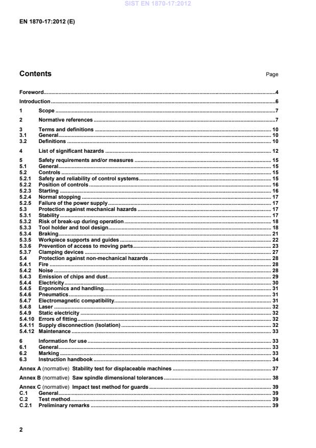
Stability test for displaceable machines . 37Annex B (normative)
Saw spindle dimensional tolerances . 38Annex C (normative)
Impact test method for guards . 39C.1 General . 39C.2 Test method . 39C.2.1 Preliminary remarks . 39SIST EN 1870-17:2012
Brake tests . 42D.1 Conditions for all tests . 42D.2 Tests . 42D.2.1 Un-braked run-down time . 42D.2.2 Braked run-down time . 42Annex ZA (informative)
Relationship between this European Standard and the Essential Requirements of EU Directive 2006/42/EC . 43Bibliography . 46 SIST EN 1870-17:2012
IEC 61029-2-2:1993. b) machines fitted with hydraulically powered machine actuators; c) machines fitted with powered work-piece positioning; d) machines fitted with the facility for either ripping, milling (including trenching and grooving), sanding and/or drilling; e) machines equipped with more than one saw spindle speed; NOTE 3 A standard to cover machines that can be used for ripping and moulding will be considered at the next revision. NOTE 4 Semi-automatic and automatic horizontal cutting cross-cut circular sawing machines with one saw unit (radial arm saws) are dealt with in EN 1870-11:2003+A1:2009. f) machines with integrated feed. This document is not applicable to manual horizontal cutting cross-cut circular sawing machines with one saw unit (manual radial arm saws) which are manufactured before the date of its publication as EN. 2 Normative references The following documents, in whole or in part, are normatively referenced in this document and are indispensable for its application. For dated references, only the edition cited applies. For undated references, the latest edition of the referenced document (including any amendments) applies. EN 614-1:2006+A1:2009, Safety of machinery — Ergonomic design principles — Part 1: Terminology and general principles EN 614-2:2000+A1:2008, Safety of machinery — Ergonomic design principles — Part 2: Interactions between the design of machinery and work tasks EN 847-1:2005+A1:2007, Tools for woodworking — Safety requirements — Part 1: Milling tools, circular saw blades SIST EN 1870-17:2012
1) EN 60439-1:1999 is amended by EN 60439-1:1999/A1:2004, based on IEC 60439-1:1999/A1:2004. 2) EN 60529:1991 is amended by EN 60529:1991/A1:2000, based on IEC 60529:1989/A1:1999. SIST EN 1870-17:2012
3) EN ISO 3745:2009 is superseded by EN ISO 3745:2012. 4) HD 22.4 S4:2004 is superseded by EN 50525-2-21:2011. SIST EN 1870-17:2012
Note 1 to entry: See Figures 1 and 2. Note 2 to entry: The arm can rotate around a vertical axis (pivoting) in a horizontal plane and the saw unit can rotate about a horizontal axis (canting) parallel to the arm. The workpiece is manually positioned on and removed from the workpiece support.
NOTE The saw blade is not in the rest position. Figure 1 — Example 1 of a manual horizontal cutting cross-cut circular sawing machine with one saw unit (manual radial arm saw) SIST EN 1870-17:2012
Figure 2 — Example 2 of a manual horizontal cutting cross-cut circular sawing machine with one saw unit (manual radial arm saw) 3.2.3 stationary machine machine designed to be located on or fixed to the floor or other parts of the structure of the premises and to be stationary during use 3.2.4 displaceable machine machine which is located on the floor, stationary during use and equipped with a device, normally wheels, which allow it to be moved between locations 3.2.5 hand feed of the saw unit manual movement of the saw unit incorporating the saw blade along the forward arm of the machine in direction of the feed movement 3.2.6 machine actuator power mechanism used to effect motion of the saw blade 3.2.7 cutting area of the saw blade area of the saw blade where it can be involved in the cutting process 3.2.8 non-cutting area of the saw blade area of the saw blade where it is not involved in the cutting process 3.2.9 cutting area of a radial arm saw area formed by the maximum left and right pivoting and canting position at maximum stroke capacity of the saw blade with the maximum saw blade diameter the machine is designed for SIST EN 1870-17:2012
3.2.11 braked run-down time time elapsed from the actuation of the stop control device up to spindle standstill with activated brake
3.2.12 information from the supplier statements, sales literature, leaflets or other documents where a manufacturer (supplier) declares either the characteristics or the compliance of the material or product to a relevant standard 3.2.13 performance level
PL discrete level used to specify the ability of safety-related parts of control systems to perform a safety function under foreseeable conditions [SOURCE: EN ISO 13849-1:2008, 3.1.23] 4 List of significant hazards This clause contains all significant hazards, hazardous situations and events (see EN ISO 12100:2010), identified by risk assessment as significant for the machines as defined in the scope and which require action to eliminate or reduce the risk by defining safety requirements and/or measures or by reference to relevant standards. These hazards are listed in Table 1. SIST EN 1870-17:2012
a) shape; 6.2.2.1, 6.2.2.2, 6.3 5.3.3, 5.3.5, 5.3.7, 5.4.5
b) relative location; 5.2.2, 5.3.3, 5.3.5, 5.3.6, 5.3.7, 5.4.3, 5.4.5
d) mass and velocity (kinetic energy of elements in controlled or uncontrolled motion); 5.3.3, 5.3.7
e) mechanical strength. 5.3.2, 5.3.3
- accumulation of energy inside the machinery:
f) elastic elements (springs); 6.2.10, 6.3.5.4 5.3.3.5
g) gases under pressure; 5.2.5, 5.3.7, 5.4.12 1.1 Crushing hazard
5.3.6 1.2 Shearing hazard 5.3.6 1.3 Cutting or severing hazard 5.3.3.5, 5.3.3.6, 5.3.6 1.4 Entanglement hazard 5.3.6 1.5 Drawing-in or trapping hazard 5.3.6 1.6 Impact hazard 5.3.7 1.7 Stabbing or puncture hazard 5.3.6.1 1.8 Friction or abrasion hazard 5.3.6.1 1.9 High pressure fluid injection or ejection hazard
6.2.10 5.4.6 2 Electrical hazards due to: 2.1 Contact of persons with live parts (direct contact) 6.2.9, 6.3.5.4 5.4.4 2.2 Contact of persons with parts which have become live under faulty conditions (indirect contact) 6.2.9 5.4.4 2.4 Electrostatic phenomena 6.2.9 5.4.9 SIST EN 1870-17:2012
5.4.3 7.2 Fire hazard 6.2.4
5.4.1 8 Hazards generated by neglecting ergonomic principles in machinery design
8.1 Unhealthy postures or excessive effort 6.2.7, 6.2.8, 6.2.11.12, 6.3.5.5, 6.3.5.6 5.2.2, 5.4.5 8.2 Hand-arm or foot-leg anatomy 6.2.8.3 5.4.5 8.6 Human error, human behaviour 6.2.8, 6.2.11.8, 6.2.11.10, 6.3.5.2, 6.4 5.2.1, 5.2.3, 5.4.10 8.7 Design, location or identification of manual controls 4.8.7, 4.11.8
5.2.2, 5.4.11 8.8 Design or location of visual display units
6.2.8.8, 6.4.2 5.3.3.5, 5.4.5 10 Unexpected start-up, unexpected overrun/overspeed (or any similar malfunction) from: 10.1 Failure/disorder of the control system 6.2.11, 6.3.5.4
5.2.1 10.2 Uncontrolled restoration of energy supply after an interruption 6.2.11.4
5.2.5 10.3 External influences on electrical equipment 6.2.11.11 5.4.7 10.6 Errors made by the operator (due to mismatch of machinery with human characteristics and abilities, see 8.6) 6.2.8, 6.2.11.8, 6.2.11.10, 6.3.5.2, 6.4 5.4.10, 6.3 11 Impossibility of stopping the machine in the best possible conditions 6.2.11.1, 6.2.11.3, 6.3.5.2
5.2.4, 5.3.4 13 Failure of the power supply 6.2.11.1, 6.2.11.4 5.2.5 14 Failure of the control circuit 6.2.11, 6.3.5.4
5.2.1 SIST EN 1870-17:2012
6.2.3, 6.2.10
5.3.3.5 18 Loss of stability / overturning of machinery 6.3.2.6
5.3.1
5 Safety requirements and/or measures 5.1 General The machine shall comply with the safety requirements and/or protective measures of Clause 5. NOTE For guidance in connection with risk reduction by design, see EN ISO 12100:2010, 6.2, and for safeguarding measures, see EN ISO 12100:2010, 6.3. In addition, the machine should be designed in accordance with the principles of EN ISO 12100:2010 for hazards relevant but not significant, which are not dealt with by this document (e.g. sharp edges of the machine frame). 5.2 Controls 5.2.1 Safety and reliability of control systems 5.2.1.1 General For the purpose of this document, safety related part of a control system means the system from the initial actuator or position detector or sensor up to and including the power control element of the final machine final actuator e.g. motor or brake. Safety related parts of the control system of this machine comprise parts concerning the following functions and they shall fulfil at least the requirements of the PL given below in accordance with the requirements of EN ISO 13849-1:2008: starting and restarting: PL=c (see 5.2.3); normal stopping: PL=c (see 5.2.4); prevention of unexpected start-up after failure of the power supply: PL=c (see 5.2.5); the braking system: PL=b or PL=c (see 5.2.4, 5.3.4); monitoring of the clamp-closing pressure (if workpiece clamping is fitted): PL=c (see 5.3.7). Verification: By checking the relevant drawings and/or circuit diagrams and inspection of the machine. 5.2.1.2 Use of protective devices Protective devices shall be in accordance with the specific standards. For the devices listed below the following requirements apply: SIST EN 1870-17:2012
For the components characteristics a confirmation from the components' manufacturers can be useful. 5.2.2 Position of controls The start and stop control for the saw spindle drive motor shall be situated either: a) incorporated in, or adjacent to the handle for operating the saw unit of the machine but not more than 600 mm from front edge of the workpiece support when the saw unit is in its rest position; or b) at the front of the machine below the workpiece support and at a minimum height of 600 mm from the floor level and within 1,0 m of the cutting line when it is at 90° to the fence. If fitted with pneumatic work-piece clamping the controls for clamping and unclamping shall be either: 1) where a manually operated controls device is used, situated at the front of the machine below the work-piece support;
2) where a foot pedal is used, situated on the floor within 1,0 m of the cutting line when it is at 90° to the fence; Where an automatically operated switch is used, it shall be ensured that the work-piece is securely clamped before chipping commences. Verification: By checking the relevant drawings, measurement and inspection of the machine. 5.2.3 Starting Before starting or restarting the machine all the safeguards shall be in place and functional. This is achieved by the interlocking arrangement described in 5.3.6. NOTE Starting means switching on the saw spindle drive motor. Start or restart shall only be possible by actuation of the start control device provided for that purpose. For electrically operated machines the requirements of EN 60204-1:2006, 9.2.5.2 apply. The direction of the rotation of the saw spindle shall be such, that the cutting force of the saw blade is directed against the fence. The safety related part of the control system for starting the rotation of the spindle (see 5.2.1) shall conform to at least PL=c in accordance with the requirements of EN ISO 13849-1:2008. Verification: By checking the relevant drawings and/or circuit diagrams, inspection of the machine and relevant functional testing of the machine. SIST EN 1870-17:2012
c) polycarbonate with a wall thickness of at least 3 mm or other plastic material passing the test in Annex C; d) cast iron with an ultimate tensile strength of at least 200 N mm-2 and a wall thickness of at least 5 mm. Verification: By checking the relevant drawings, tensile strength, measurement, for materials with characteristics other than those given for polycarbonate in c) above by performing the test in Annex C and inspection of the machine. NOTE For the ultimate tensile strength a confirmation from the manufacturer of the material can be useful. 5.3.3 Tool holder and tool design 5.3.3.1 Saw blade design If the machine is fitted with saw blades, they shall be in accordance with the requirements of
EN 847-1:2005+A1:2007. See also 6.3 j). Verification: By checking the relevant drawings and inspection of the machine. 5.3.3.2 Saw spindle design The saw spindle shall be manufactured from steel with an ultimate tensile strength of at least 580 N mm-2 and fulfil at least the tolerances given in Annex B. Verification: By checking the relevant drawings, measurement and relevant functional testing of the machine. NOTE For the ultimate tensile strength a confirmation from the manufacturer of the material can be useful. SIST EN 1870-17:2012
Figure 3 — Saw flange detail (clamping surface) 5.3.3.5 Stroke control A handle shall be provided to move the saw unit during the cutting stroke. This handle shall be so designed and positioned that ergonomic principles are observed (see also 5.4.5). In its rest position, the saw unit shall be provided with an automatic retaining latch. The retaining latch release control shall be positioned on or adjacent to the handle for moving the saw unit along the arm to allow the
...