


prEN 16925
(Main)Fixed firefighting systems - Automatic residential sprinkler systems - Design, installation and maintenance
General Information
- Abstract
This document specifies requirements and gives recommendations for the design, installation, water supplies and backflow prevention, commissioning, maintenance and testing of fixed residential fire sprinkler systems in buildings for residential occupancies.
This document is intended for use by those concerned with purchasing, designing, installing, testing, inspecting, approving, operating and maintaining automatic residential sprinkler systems, in order that such equipment will function as intended throughout its life.
This document identifies construction details of buildings which are the minimum necessary for satisfactory performance of residential sprinkler systems complying with this standard.
This document applies to any addition, extension, repair or other modification to the residential sprinkler system.
This document does not cover situations such as arson where fires of a malicious intent may be started in multiple locations simultaneously.
- Status
- Not Published
- Publication Date
- 20-Dec-2027
- Technical Committee
- CEN/TC 191 - Fixed firefighting systems
- Drafting Committee
- CEN/TC 191/WG 5 - Sprinkler systems
- Current Stage
- 4060 - Closure of enquiry - Enquiry
- Start Date
- 16-Jul-2026
- Due Date
- 27-Oct-2026
- Completion Date
- 16-Jul-2026


Overview
prEN 16925 is the draft European Standard developed by CEN for fixed firefighting systems, focusing specifically on the design, installation, commissioning, maintenance, and testing of automatic residential sprinkler systems in buildings intended for residential occupancies. The standard outlines the minimum requirements and provides recommendations to ensure these life safety systems perform consistently and effectively throughout their operational life. It is relevant to professionals across the fire protection industry, including system designers, installers, building owners, purchasers, and maintenance providers.
Automatic residential sprinkler systems are proven to detect and control fires at an early stage, significantly improving occupant safety and property protection in homes, apartments, care homes, hostels, and similar settings. prEN 16925 supports a standardized approach, ensuring the reliability and functionality of these essential fire safety installations.
Key Topics
System Design and Planning
- Requirements for contract planning, documentation, and which parties need to be consulted
- Details on preliminary design stages, including layout drawings and summary schedules
- Identifies minimum construction conditions for satisfactory system performance
Installation and Water Supply
- Criteria for proper installation, pipe layout, and hydraulic design
- Specifications for acceptable water supply arrangements, including water main, storage tanks, and pumps
- Guidelines for backflow prevention to protect potable water quality
Commissioning and Testing
- Procedures for initial system commissioning, including verification of hydraulic performance and alarm functions
- Requirements for completion certificates and system documentation
Inspection and Maintenance
- Regular inspection, testing, and maintenance routines to maintain system readiness
- Precautions during ongoing work and actions required after system activation
Modifications and Extensions
- Applicability to additions, extensions, repairs, or modifications to existing residential sprinkler systems
Safety and Performance Provisions
- Emphasis on life and property protection while acknowledging that sprinkler systems supplement - not replace - other fire safety approaches such as alarm systems, structural fire resistance, escape routes, and portable extinguishers
Areas of Application and Limitations
- Applies to new installations and modifications in a wide range of residential buildings
- Explicitly excludes coverage in deliberate arson situations where multiple ignition points are set simultaneously
Applications
Residential sprinkler systems designed and maintained in accordance with prEN 16925 can be applied in:
- Single-family homes and houses, including prefabricated dwellings
- Apartment buildings and multi-family residences
- Residential care homes and assisted living facilities
- Student accommodation, hostels, and boarding houses
- Child or adult day-care centres within residential buildings
- Bed and breakfast establishments and small hotels
The standard is particularly relevant where compliance with building and fire safety codes is required, for risk mitigation in vulnerable occupancies, or where insurance providers specify automatic sprinkler installation as a condition for coverage. prEN 16925 ensures that any addition or alteration to a residential sprinkler system upholds the same safety standards as new installations.
Related Standards
prEN 16925 forms part of a comprehensive series of fire safety standards. Related standards include:
- EN 12845 - Fixed firefighting systems – Automatic sprinkler systems – Design, installation, and maintenance
- EN 12259 (all parts) - Components for sprinkler and water spray systems
- EN 14972 (all parts) - Water mist systems for fixed firefighting appliances
- EN 1717 - Protection against water pollution by backflow
- EN 54 (all parts) - Fire detection and fire alarm systems
- EN 60529 - Degrees of protection provided by enclosures (IP Code)
- EN 12845 - Design and installation specifically for non-residential/industrial sprinkler systems
- EN 15004, EN 12416, EN 13565 - Gas, powder, and foam fixed firefighting systems
Consult these standards for additional guidance on complementary systems and technical requirements in the broader context of building fire protection.
By ensuring consistent design, installation, and maintenance of automatic residential sprinkler systems, prEN 16925 supports safer, more resilient living spaces and compliance with European fire safety regulations.
Relations
- Effective Date
- 26-Feb-2025
Get Certified
Connect with accredited certification bodies for this standard

CIS Institut d.o.o.
Personal Protective Equipment (PPE) certification body. Notified Body NB-2890 for EU Regulation 2016/425 PPE.

Kiwa BDA Testing
Building and construction product certification.
Kmetijski inštitut Slovenije
Agricultural Institute of Slovenia. Soil testing, plant health, agricultural product analysis.
Sponsored listings
Frequently Asked Questions
prEN 16925 is a draft published by the European Committee for Standardization (CEN). Its full title is "Fixed firefighting systems - Automatic residential sprinkler systems - Design, installation and maintenance". This standard covers: This document specifies requirements and gives recommendations for the design, installation, water supplies and backflow prevention, commissioning, maintenance and testing of fixed residential fire sprinkler systems in buildings for residential occupancies. This document is intended for use by those concerned with purchasing, designing, installing, testing, inspecting, approving, operating and maintaining automatic residential sprinkler systems, in order that such equipment will function as intended throughout its life. This document identifies construction details of buildings which are the minimum necessary for satisfactory performance of residential sprinkler systems complying with this standard. This document applies to any addition, extension, repair or other modification to the residential sprinkler system. This document does not cover situations such as arson where fires of a malicious intent may be started in multiple locations simultaneously.
This document specifies requirements and gives recommendations for the design, installation, water supplies and backflow prevention, commissioning, maintenance and testing of fixed residential fire sprinkler systems in buildings for residential occupancies. This document is intended for use by those concerned with purchasing, designing, installing, testing, inspecting, approving, operating and maintaining automatic residential sprinkler systems, in order that such equipment will function as intended throughout its life. This document identifies construction details of buildings which are the minimum necessary for satisfactory performance of residential sprinkler systems complying with this standard. This document applies to any addition, extension, repair or other modification to the residential sprinkler system. This document does not cover situations such as arson where fires of a malicious intent may be started in multiple locations simultaneously.
prEN 16925 is classified under the following ICS (International Classification for Standards) categories: 13.220.20 - Fire protection. The ICS classification helps identify the subject area and facilitates finding related standards.
prEN 16925 has the following relationships with other standards: It is inter standard links to EN 16925:2018. Understanding these relationships helps ensure you are using the most current and applicable version of the standard.
prEN 16925 is available in PDF format for immediate download after purchase. The document can be added to your cart and obtained through the secure checkout process. Digital delivery ensures instant access to the complete standard document.
Standards Content (Sample)
SLOVENSKI STANDARD
01-junij-2026
Vgrajeni gasilni sistemi - Avtomatski sprinklerski sistemi za bivalne površine -
Načrtovanje, vgradnja in vzdrževanje
Fixed firefighting systems - Automatic residential sprinkler systems - Design, installation
and maintenance
Ortsfeste Brandbekämpfungsanlagen - Automatische Sprinkleranlagen für
Wohnbereiche - Planung, Installation und Instandhaltung
Installations fixes de lutte contre l’incendie - Systèmes d’extinction automatiques du type
sprinkleur résidentiel - Conception, installation et maintenance
Ta slovenski standard je istoveten z: prEN 16925
ICS:
13.220.20 Požarna zaščita Fire protection
2003-01.Slovenski inštitut za standardizacijo. Razmnoževanje celote ali delov tega standarda ni dovoljeno.
DRAFT
EUROPEAN STANDARD
NORME EUROPÉENNE
EUROPÄISCHE NORM
April 2026
ICS 13.220.20 Will supersede EN 16925:2018
English Version
Fixed firefighting systems - Automatic residential
sprinkler systems - Design, installation and maintenance
Installations fixes de lutte contre l'incendie - Systèmes Ortsfeste Brandbekämpfungsanlagen - Automatische
d'extinction automatiques du type sprinkleur Sprinkleranlagen für Wohnbereiche - Planung,
résidentiel - Conception, installation et maintenance Installation und Instandhaltung
This draft European Standard is submitted to CEN members for enquiry. It has been drawn up by the Technical Committee
CEN/TC 191.
If this draft becomes a European Standard, CEN members are bound to comply with the CEN/CENELEC Internal Regulations
which stipulate the conditions for giving this European Standard the status of a national standard without any alteration.
This draft European Standard was established by CEN in three official versions (English, French, German). A version in any other
language made by translation under the responsibility of a CEN member into its own language and notified to the CEN-CENELEC
Management Centre has the same status as the official versions.
CEN members are the national standards bodies of Austria, Belgium, Bulgaria, Croatia, Cyprus, Czech Republic, Denmark, Estonia,
Finland, France, Germany, Greece, Hungary, Iceland, Ireland, Italy, Latvia, Lithuania, Luxembourg, Malta, Netherlands, Norway,
Poland, Portugal, Republic of North Macedonia, Romania, Serbia, Slovakia, Slovenia, Spain, Sweden, Switzerland, Türkiye and
United Kingdom.
Recipients of this draft are invited to submit, with their comments, notification of any relevant patent rights of which they are
aware and to provide supporting documentation.
Warning : This document is not a European Standard. It is distributed for review and comments. It is subject to change without
notice and shall not be referred to as a European Standard.
EUROPEAN COMMITTEE FOR STANDARDIZATION
COMITÉ EUROPÉEN DE NORMALISATION
EUROPÄISCHES KOMITEE FÜR NORMUNG
CEN-CENELEC Management Centre: Rue de la Science 23, B-1040 Brussels
© 2026 CEN All rights of exploitation in any form and by any means reserved Ref. No. prEN 16925:2026 E
worldwide for CEN national Members.
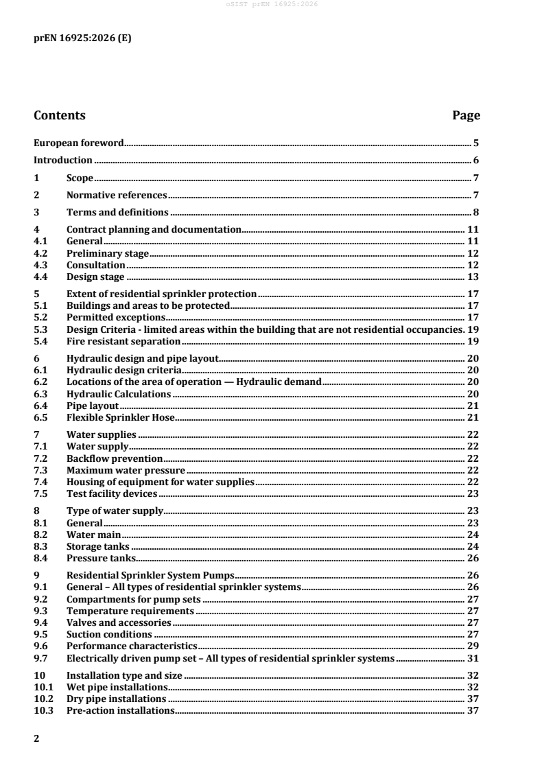
Contents Page
European foreword . 5
Introduction . 6
1 Scope . 7
2 Normative references . 7
3 Terms and definitions . 8
4 Contract planning and documentation. 11
4.1 General . 11
4.2 Preliminary stage . 12
4.3 Consultation . 12
4.4 Design stage . 13
5 Extent of residential sprinkler protection . 17
5.1 Buildings and areas to be protected . 17
5.2 Permitted exceptions . 17
5.3 Design Criteria - limited areas within the building that are not residential occupancies . 19
5.4 Fire resistant separation . 19
6 Hydraulic design and pipe layout . 20
6.1 Hydraulic design criteria . 20
6.2 Locations of the area of operation — Hydraulic demand . 20
6.3 Hydraulic Calculations . 20
6.4 Pipe layout . 21
6.5 Flexible Sprinkler Hose . 21
7 Water supplies . 22
7.1 Water supply . 22
7.2 Backflow prevention . 22
7.3 Maximum water pressure . 22
7.4 Housing of equipment for water supplies . 22
7.5 Test facility devices . 23
8 Type of water supply . 23
8.1 General . 23
8.2 Water main . 24
8.3 Storage tanks . 24
8.4 Pressure tanks . 26
9 Residential Sprinkler System Pumps . 26
9.1 General – All types of residential sprinkler systems . 26
9.2 Compartments for pump sets . 27
9.3 Temperature requirements . 27
9.4 Valves and accessories . 27
9.5 Suction conditions . 27
9.6 Performance characteristics . 29
9.7 Electrically driven pump set – All types of residential sprinkler systems . 31
10 Installation type and size . 32
10.1 Wet pipe installations . 32
10.2 Dry pipe installations . 37
10.3 Pre-action installations . 37
11 Spacing and location of sprinklers . 37
11.1 General . 37
11.2 Spacing of residential sprinklers . 38
11.3 Distance of residential sprinklers from walls . 39
11.4 Deflector position of residential sprinklers . 39
11.5 Obstructions in relation to residential sprinklers . 39
11.6 Small compartments . 46
12 Sprinkler design characteristics and uses . 46
12.1 General . 46
12.2 Sprinkler types and application . 46
12.3 Sprinkler nominal operating temperatures . 46
12.4 Sprinkler rosettes and cover plates . 47
13 Valves and gauges . 47
13.1 Control valve set . 47
13.2 Stop valves . 48
13.3 Drain requirements . 48
13.4 Test valves . 48
13.5 Pressure gauges . 48
14 Alarms and alarm devices . 49
14.1 System monitoring and alarm transmission . 49
14.2 Water flow A alarm . 49
14.3 Alarm connection . 49
15 Pipework . 50
15.1 Pipe system . 50
15.2 Pipe supports . 52
16 Signs, notices and information . 54
16.1 Block plan . 54
16.2 Signs and notices . 54
17 Commissioning tests . 56
17.1 General . 56
17.2 All pipework . 56
17.3 Dry pipework . 56
17.4 Completion certificate and documents . 56
18 Inspection, testing and maintenance. 56
18.1 General . 56
18.2 Spare sprinklers . 57
18.3 Precautions while carrying out work . 57
18.4 Annual inspection . 57
18.5 Long-term inspections . 58
Annex A (normative) Sprinkler system zoning . 59
A.1 General . 59
A.2 Guidance for zoned installations . 59
Annex B (normative) Sprinkler system monitoring. 60
B.1 Type 1 systems . 60
B.2 Type 2 and 3 systems . 60
B.3 Functions to be monitored . 60
Annex C (normative) Transmission of alarms. 62
C.1 Type 1 systems . 62
C.2 Type 2 and Type 3 systems . 62
Annex D (normative) Hydraulic calculations . 64
D.1 Static pressure . 64
D.2 Flow from a sprinkler . 64
D.3 Pipe friction loss . 64
D.4 Pressure loss through fittings and valves . 65
D.5 Velocity . 67
D.6 Accuracy of calculations . 67
Annex E (normative) Long term inspection and testing of pipework and sprinklers . 68
Annex F (informative) Special circumstances . 69
Annex G (informative) Typical water supply arrangements . 70
Annex H (informative) Precautions and procedures when a system is not fully operational . 73
H.1 Minimizing the fire safety risk when a sprinkler system is shut down . 73
H.2 Planned shut-down . 73
H.3 Unplanned shut-down . 73
H.4 Action following sprinkler operation . 74
Annex I (informative) Hydraulic test . 75
Annex J (informative) New technology . 77
Bibliography . 78
European foreword
This document (prEN 16925:2026) has been prepared by Technical Committee CEN/TC 191 “Fixed
firefighting systems”, the secretariat of which is held by BSI.
This document is currently submitted to the CEN Enquiry.
This document will supersede EN 16925:2018 and EN 16925:2018/AC:2020.
This document is part of a series of standards which includes the following:
— EN 12259 (all parts), Fixed firefighting systems – Components for sprinkler and water spray systems;
— EN 12845, Fixed firefighting systems – Automatic sprinkler systems;
— EN 14972 (all parts), Fixed firefighting systems – Water mist systems;
— EN 12094 (all parts), Fixed firefighting systems – Components for gas extinguishing systems;
— EN 15004 (all parts), Fixed firefighting systems – Gas extinguishing systems;
— EN 12416 (all parts), Fixed firefighting systems – Powder systems;
— ISO 6184 (all parts), Fixed firefighting systems – Explosion protection systems;
— EN 13565 (all parts), Fixed firefighting systems – Foam systems;
— EN 671 (all parts), Fixed firefighting systems – Hose systems;
— EN 12101 (all parts), Smoke and heat control systems.
Introduction
Sprinkler systems have demonstrated their value in protecting life and property in industrial and
commercial applications for over 100 years. The recognition that the largest number of deaths from fire
occur in the home has led to the introduction of sprinkler systems specifically designed for residential
occupancies.
A correctly designed and installed residential sprinkler system can detect and control a fire at an early stage
of development and activate a fire alarm. Operation of the system rapidly reduces the rate of production of
heat and smoke, allowing more time for occupants to escape to safety or be rescued.
Sprinklers operate at predetermined temperatures to discharge water over the area below. Only the
sprinklers near the fire, which are individually heated above their operating temperature, will operate. The
flow of water initiates a fire alarm signal to draw attention to the operation of the system. The operating
temperature is generally selected to suit ambient temperature conditions.
It is essential that residential sprinkler systems are properly maintained and regularly tested to ensure
correct operation in case of fire.
It should not be assumed that the provision of a residential sprinkler system eliminates the need for other
means of detecting and fighting fires and it is important to consider the fire precautions in the occupancy as
a whole. Structural fire resistance, escape routes, smoke alarms, fire alarm systems, provision of portable
extinguishers, training and information all need consideration.
It is assumed that the building design and construction will be in accordance with local building codes and
national requirements. If the residential sprinkler system is to be used to compensate for other fire
protection measures, such as walls or doors, building authorities may require the installation of a system
with additional measures to enhance performance and/or reliability.
Only a competent person should undertake the design, installation, inspection, testing and maintenance of
residential sprinkler systems. This standard does not necessarily cover all local or national legislative
requirements, which may take precedence over this standard.
1 Scope
This document specifies requirements and gives recommendations for the design, installation, water
supplies and backflow prevention, commissioning, maintenance and testing of fixed residential fire sprinkler
systems in buildings for residential occupancies.
This document is intended for use by those concerned with purchasing, designing, installing, testing,
inspecting, approving, operating and maintaining automatic residential sprinkler systems, in order that such
equipment will function as intended throughout its life.
This document identifies construction details of buildings which are the minimum necessary for satisfactory
performance of residential sprinkler systems complying with this standard.
This document applies to any addition, extension, repair or other modification to the residential sprinkler
system.
This document does not cover situations such as arson where fires of a malicious intent may be started in
multiple locations simultaneously.
2 Normative references
The following documents are referred to in the text in such a way that some or all of their content constitutes
requirements of this document. For dated references, only the edition cited applies. For undated references,
the latest edition of the referenced document (including any amendments) applies.
EN 54 (all parts), Fire detection and fire alarm systems
EN 1057, Copper and copper alloys — Seamless, round copper tubes for water and gas in sanitary and heating
applications
EN 10205, Cold reduced tinmill products - Blackplate
EN 10216-1, Seamless steel tubes for pressure purposes - Technical delivery conditions - Part 1: Non-alloy steel
tubes with specified room temperature properties
EN 10217-1, Welded steel tubes for pressure purposes - Technical delivery conditions - Part 1: Electric welded
and submerged arc welded non-alloy steel tubes with specified room temperature properties
EN 10255, Non-Alloy steel tubes suitable for welding and threading — Technical delivery conditions
EN 12259-1, Fixed firefighting systems — Components for sprinkler and water spray systems — Part 1:
Sprinklers
EN 12259-5, Fixed firefighting systems - Components for sprinkler and water spray systems - Part 5: Water flow
detectors
EN 12259-14, Fixed firefighting systems — Components for sprinkler and water spray systems — Part 14:
Sprinklers for residential applications
EN 12845, Fixed firefighting systems — Automatic sprinkler systems — Design, installation and maintenance
EN 1717, Protection against pollution of water intended for human consumption in potable water installations
and general requirements for devices to prevent pollution by backflow
EN 60529, Degrees of protection provided by enclosures (IP Code)
EN 60730-1, Automatic electrical controls for household and similar use — Part 1: General requirements
(IEC 60730-1)
EN 60898-1, Electrical accessories - Circuit-breakers for overcurrent protection for household and similar
installations - Part 1: Circuit-breakers for a.c. operation
EN 806-5, Specifications for installations inside buildings conveying water for human consumption - Part 5:
Operation and maintenance
EN IEC 60331-1, Tests for electric cables under fire conditions - Circuit integrity - Part 1: Test method for fire
with shock at a temperature of at least 830°C for cables of rated voltage up to and including 0,6/1,0 kV and
with an overall diameter exceeding 20 mm
3 Terms and definitions
For the purposes of this document, the terms and definitions given in EN 12845 and the following apply.
ISO and IEC maintain terminological databases for use in standardization at the following addresses:
• IEC Electropedia: available at http://www.electropedia.org/
• ISO Online browsing platform: available at http://www.iso.org/obp
3.1
A alarm
system flow alarm that indicates a possible fire
3.2
alarm receiving unit
control panel capable of initiating an alarm
3.3
area of operation
maximum area over which is it assumed, for design purposes, that sprinklers will operate in a fire
3.4
authority
organization or individual responsible for approving sprinkler systems, equipment and procedures
EXAMPLE Examples include the fire and building control authorities, the fire insurers, the local water authority
and other appropriate public authorities.
3.5
sprinkler (automatic)
nozzle with a thermally sensitive sealing device which opens to discharge water for fire-fighting
3.6
B alarm
indication of a technical fault or an abnormal condition
3.7
bed and breakfast
accommodation with up to four lettable rooms and up to three storeys, where the owner lives on the
premises and no meal other than breakfast is provided
3.8
competent person
person, suitably trained and qualified by knowledge, understanding and practical experience, and provided
with the necessary instructions, to enable the required task(s) to be carried out correctly
3.9
design area of coverage
floor area protected by a sprinkler
3.10
design density
discharge flow from each sprinkler, divided by the area covered
Note 1 to entry: Expressed in mm/min.
3.11
design sprinklers
individual sprinklers or groups of sprinklers within the same residential compartment located at the most
hydraulically favourable and unfavourable locations, and which are used to determine the hydraulic design
demand of the sprinkler system
3.12
dwelling
building that contains units intended to be used for habitation purposes
Note 1 to entry: The dwelling may be owned, rented, leased, let or hired out.
3.13
effective capacity
volume of stored water available, taking into account the air gap at the top and the unusable water at the
base of the tank
Note 1 to entry: the effective capacity is affected by a vortex letting air into the pump suction
3.14
flexible sprinkler hose
flexible device assembly and its supporting components used solely for connecting a single fire sprinkler to a
range pipe
3.15
horizontal ceiling
ceiling with a slope not exceeding 9,5°
3.16
K-factor
constant which characterises the hydraulic performance of a sprinkler and is used to calculate the water
flow through the sprinkler from the square root of the water pressure
3.17
manufacturer’s specification
document published by a manufacturer which is intended to supplement this standard with additional
technical information with regards to design, installation and maintenance
3.18
maximum flow demand
Q
max
flow at the point of intersection of the pressure-flow demand characteristic of the most favourable area of
operation of the sprinkler system and the water supply pressure-flow characteristic with the suction source
at its normal level
3.19
most favourable area
area of operation for which the water flow is at its maximum for a specified pressure, measured at the main
control valve or pump set
3.20
most unfavourable area
area of operation for which the system pressure, when measured at the main control valve or pump set, is
required to be at its maximum to achieve the specified design density
3.21
normal water level
water level at the water supply needed to give the required effective capacity in relation to the low water
level, including any necessary margins
3.22
premix anti-freeze solution
combination of an anti-freeze and water that is mixed, packaged and labelled by a manufacturer using a
quality controlled process that ensures product homogeneity and concentration as specified in order to
ensure localised concentrations do not arise in the pipe network
3.23
residential pump
pump dedicated to supply the sprinkler system only
3.24
sprinkler, quick response spray
½
sprinkler that gives a downward paraboloid pattern of water discharge and which has an RTI of 50 (m-s) or
less according to EN 12259-1, either upright, pendent or sidewall type
3.25
remote test valve
test facility incorporating a test valve with any associated fittings and pipework, delivering a flow equivalent
to the discharge from a single sprinkler with the smallest K-factor in the system, connected at the
hydraulically most remote location on a distribution pipe
3.26
residential compartment
space completely enclosed by walls and a ceiling, where
a) the total width of openings in a single wall to an adjacent room is not more than 2 500 mm and all
openings have a lintel depth of not less than 200 mm; or
b) there is a single opening without a lintel in a wall to an adjacent room of not more than 900 mm in width
and there are no other openings
3.27
residential occupancies
part of a building only containing dwellings
Note 1 to entry: This includes common areas such as separate small storage rooms up to 9 m used only by the
residents, the entrance area and boiler rooms.
3.28
residential sprinkler
type of sprinkler in accordance with EN 12259-14
3.29
shadow area
small area which is not wetted by the residential sprinkler due to an obstruction such as a wall or partition
3.30
sloped ceiling
ceiling with a slope exceeding 9,5°
3.31
small hotel
hotel or guest house with up to 14 lettable rooms and an occupied floor at a height of up to four storeys or
18 m above the lowest fire brigade access level, without a licence to sell alcohol
3.32
uoccupied attics
uppermost spaces that are empty and not being used for any purposes, including storage
4 Contract planning and documentation
4.1 General
The information specified in this clause shall be provided to the user or owner as appropriate. All drawings
and information documents shall carry the following information:
a) the name of the user and the owner, where known;
b) the address and location of premises;
c) the type of occupancies found in each part of the building;
d) the name of the designer;
e) the name of the person responsible for reviewing the design, who shall not be the designer and may be a
third party;
f) date and number of issue.
4.2 Preliminary stage
The following information shall be provided:
a) a block plan of the premises showing:
1) the type of application (see Table 1);
2) the extent of the system with details of any unprotected areas;
3) location of control valve set(s);
4) location of zone stop valves (if applicable);
5) a cross-section of the full height of the building(s) showing the height of the highest sprinkler above
a stated datum level;
b) general information about the water demand, water main pressure and flow data if a water main
connection is to be used, and a plan of the test site;
c) description of any deviations from the requirements of this standard and the reasons why.
Table 1 — System types and applications
System Type Application
1 One or two-family dwelling / house
Pre-fabricated house
Bed and breakfast
a
2 Apartment building
a, b
House with multiple households sharing facilities
a, c
Care home
a, c
Child or adult day-care centre
a
Student accommodation
a
3 Care home
a
Small hotels or hostels
a
Limited to four storeys or 18 m height.
b
Shared facilities are bathrooms and/or kitchens and living rooms.
c
10 or fewer residents.
NOTE Some countries may have a national annex with guidance on the maximum height and any additional
requirements for apartment buildings higher than 18 m to be protected with a residential sprinkler system.
See Annex F for guidance on special circumstances for the applications in Table 1.
4.3 Consultation
Where a residential sprinkler system or an extension or alteration to a residential sprinkler system is being
considered for new or existing buildings, the following should be consulted where known and, where
necessary, their approval sought at an early stage:
a) the water undertaker (provider);
b) the fire authority;
c) the building control body;
d) the insurer(s), where insurance is in place, of the dwelling and dwelling contents.
NOTE This list is not exhaustive and national regulations may require consultation with additional bodies.
4.4 Design stage
4.4.1 General
The information provided shall include a summary schedule (see 4.4.2), complete installation layout
drawings of the residential sprinkler installation(s) (see 4.4.3) and details of the water supplies (see 4.4.4).
4.4.2 Summary schedule
The summary schedule shall give the following information:
a) the name of project;
b) all drawings or document reference numbers;
c) the type(s) of installation(s) and the nominal diameter(s) of each control valve set;
d) the number or references of each control valve set in the system;
e) the number of sprinklers on each control valve set;
f) the pipework volume in the case of dry installations.
4.4.3 Installation layout drawings
4.4.3.1 General
Layout drawings shall include the following information:
a) the system type (see Table 1);
b) plan and cross sections showing construction details of floors, ceilings, roofs, exterior walls and walls
separating sprinklered and non-sprinklered areas;
c) the following information for each type of sprinkler:
1) nominal operating temperature;
2) K-factor;
3) response type;
4) orientation;
and for each type of residential sprinkler the maximum area of coverage;
d) the location of access to and the type of control valve sets;
e) the location and details of any water flow, and air or water pressure alarm switches;
f) the location and size of any subsidiary valves, subsidiary stop valves and drain valves;
g) the location of all test valves;
h) the location and details of any alarm receiving unit;
i) the location of all concealed pipework;
j) a key to the symbols used.
4.4.3.2 Calculation
The following shall be given, with detailed calculations, either on purpose designed work sheets or as a
computer printout:
a) the hydraulic calculation program name and version number;
b) the date of the worksheet or print-out;
c) the actual internal diameters of all pipes used in the calculation;
d) for each design area of operation;
1) the area identification;
2) the system type;
3) the specified design density in millimetres per minute or the minimum flow and pressure according
to the instruction chart in EN 12259-14;
4) the number of sprinklers in the area of operation;
5) the sprinkler K-factor;
6) the maximum area covered per sprinkler in square metres;
7) detailed and dimensioned working drawings showing the following:
i) the node or pipe reference scheme used to identify pipes, junctions, sprinklers and fittings
which need hydraulic consideration;
ii) the position of the sprinkler or sprinklers requiring the greatest hydraulic demand;
iii) the sprinklers upon which the design density is based;
iv) the height above datum of each point of identified pressure value;
e) for each operating sprinkler:
1) the sprinkler node or reference number;
2) the nominal K factor;
3) the flow through the sprinkler in litres per minute;
4) the inlet pressure to the sprinkler or sprinkler assembly in bar;
f) for each hydraulically significant pipe:
1) pipe node or other reference number;
2) nominal bore in millimetres;
3) the Hazen-Williams constant;
4) flow in litres per minute;
5) velocity in metres per second;
6) length in metres;
7) numbers, types and equivalent length in metres of fittings and components;
8) static head change in metres;
9) pressures at inlet and outlet in bar;
10) friction loss in bar;
11) indication of flow direction.
4.4.4 Water supply
4.4.4.1 Water supply drawings
The drawings shall show pipework from the water main or storage tank to the control valve set. A key to the
symbols shall be included. The position and type of stop and non-return valves and any pressure reducing
valves, water meters, back-flow preventers and any connections supplying water for other services, shall be
indicated. Examples of typical water supply arrangements are shown in Annex G.
For full holding capacity stored-water systems, the pipework from the tank should be detailed in the
drawings. For reduced capacity stored-water systems, the pipework should be detailed either from where
the inflow pipe connects to a shared supply or from where the dedicated inflow supply enters the building.
Systems supplied from the water main should have the pipework detailed from where it enters the building.
4.4.4.2 Hydraulic calculation
A hydraulic calculation shall show that the minimum water supply characteristics can provide the required
pressure and flow at the control valve set.
Where the water supply is from a water main it can be necessary to assume a supply flow and pressure at
the design stage, include an allowance for pressure loss from the water main and to confirm adequate supply
once the water main is installed. See Annex I for a method to conduct the hydraulic test.
4.4.4.3 Town main
Where a town main forms the supply or provides inflow to a reduced capacity tank, the following details
shall be given:
a) the nominal diameter of the main, where known;
b) the demand pressure and flow characteristics for the hydraulically most demanding area of operation,
with the pressure measured at the ‘C’ gauge;
c) when allowed by the water undertaker, a pressure and flow characteristic graph indicating the available
pressure at any flow up to the maximum flow demand.
4.4.4.4 Automatic pump set
The following details of each automatic pump set shall be provided:
a) a pump characteristic curve for low water level 'X' (see Figure 3) showing the calculated performance of
the pump or pumps under installed conditions at the control valve 'C' gauge;
b) the pump manufacturer's data sheet showing the following:
1) the generated head graph;
2) the power absorption graph;
3) the net positive suction head (NPSH) graph;
c) the installer's data sheet showing the pump set installed performance pressure/flow characteristics, at
the control valve 'C' gauge for normal water level and for low water level 'X' and at the pump outlet
pressure gauge for normal water level;
d) the height difference between the control valve 'C' gauge and the pump delivery pressure gauge;
e) the available and the specified NPSH at maximum required flow;
f) for a submersible pump the minimum depth of water in accordance with the manufacturer’s
instructions;
g) the most demanding sprinkler pressure/flow characteristic for the hydraulically most unfavourable and
the most favourable area of operation calculated at the control valve 'C' gauge;
h) a schematic drawing of the electrical system.
4.4.4.5 Storage tank
The following details shall be provided:
a) the location;
b) the total volume of the tank;
c) the effective capacity of the tank and duration;
d) the inflow for reduced capacity tanks;
e) the vertical distance between the pump inlet centre line and the tank low water level 'X';
f) details of the tank and roof construction;
g) protection against freezing;
h) protection against backflow;
i) low and normal water levels X and N;
j) height of gravity tank above the highest sprinkler.
4.4.4.6 Pressure tank
The following details shall be provided:
a) the location;
b) the total volume of the tank;
c) the volume of stored water;
d) the air pressure;
e) the height of the highest and/or hydraulically most remote
...