

prEN IEC 61869-14:2026
(Main)Transformateurs de mesure - Partie 14: Exigences supplémentaires concernant les transformateurs de courant pour application en courant continu
- Status
- Not Published
- Publication Date
- 06-Apr-2028
- Technical Committee
- CLC/TC 38 - Instrument transformers
- Current Stage
- 4020 - Enquiry circulated - Enquiry
- Start Date
- 30-Oct-2026
- Due Date
- 30-Jun-2025
- Completion Date
- 30-Oct-2026

prEN IEC 61869-14:2026 is a CENELEC/IEC draft for instrument transformers, prepared by IEC technical committee 38. It sets additional requirements for current transformers for DC applications, so engineers can specify, test and mark these transformers for measuring, protection and control use in power systems above 1,5 kV DC.
What does prEN IEC 61869-14:2026 specify?
prEN IEC 61869-14:2026 specifies the DC-specific requirements for current transformers intended for DC applications, whatever the technology used. It is used together with IEC 61869-1:2023 and follows the same structure, adding or modifying clauses where DC service needs different ratings, insulation, accuracy and test methods.
The document applies to newly manufactured current transformers with analogue or digital output. It covers measuring, protection and control applications, and it also includes bushing type current transformers when they are installed on systems above 1,5 kV DC.
The standard is organized into Clause 1 to Clause 10, followed by Annexes A to I and Annexes 14A to 14C. The annexes add guidance, test methods and voltage definitions for DC applications.
| Annex | What it covers |
|---|---|
| A (normative) | Identification of test specimen |
| B (informative) | Recommendation for contents of failure reports |
| C (informative) | Fire hazard |
| D (informative) | Sample test |
| E (informative) | Thermal time constant estimation in temperature rise tests |
| F (informative) | Extending the validity of type tests or special tests |
| G (informative) | Equivalent diameter for irregular insulating parts |
| H (informative) | Test circuits |
| I (normative) | Seismic qualification of instrument transformers |
| 14A (informative) | Equivalent thermal current in CTs for DC application |
| 14B (normative) | Composite AC/DC voltages |
| 14C (informative) | Voltage definitions |
What are the key requirements of prEN IEC 61869-14:2026?
prEN IEC 61869-14:2026 sets the ratings, insulation rules, accuracy classes and tests that are specific to DC CTs. In practice, it tells the manufacturer what to declare, what the purchaser can specify, and what the test laboratory has to verify.
Application and system configurations
The standard distinguishes DC CTs used in line-commutated converters (LCC) and voltage-source converters (VSC). It identifies several measurement positions, such as CT1, CT2, CT3 and CT4, because the voltage and current waveforms differ by location.
That matters because a CT on the AC side, DC side or filter side of a converter is exposed to different harmonic content and different insulation stress. The document uses these application types to set the relevant rating and test conditions.
Ratings and electrical values
The standard gives selected ratings for DC CTs, including highest voltage for equipment, rated primary current, rated continuous thermal current, rated burden, accuracy class, fault analysis current factor and rated step response time. Standard rated primary current values are 1200 A, 2000 A and 4000 A, and standard analogue secondary voltages are 150 mV, 1,66 V, 5 V and 10 V.
It also states that the rated frequency is 0, meaning DC. For digital outputs in accordance with IEC 61869-9, the rated delay time is zero, while point-to-point links without timestamps require the manufacturer to demonstrate the delay time.
Insulation and environmental stress
For insulation, the document bases the rated primary terminal insulation level on the highest voltage for equipment and on the DC system voltage. It also addresses composite AC/DC voltage stress, including cases with significant harmonics and 3PWM operation.
For equipment at or above 20 kV, the document adds requirements for partial discharge, chopped impulse, capacitance and dielectric dissipation factor, and pollution performance. For outdoor equipment at or above 100 kV, it also includes wet testing and artificial pollution testing. This is important because DC insulation behaviour depends strongly on voltage polarity, pollution and the presence of AC components.
Accuracy and dynamic performance
The document gives accuracy classes 0,1 - 0,2 - 0,5 - 1 - 3, and separate limits for DC current measurement, AC current measurement and wide-band harmonic performance. It also defines standard values for accuracy limit factor, fault analysis current factor, and extended primary current factor.
That means a user has to choose whether the CT is intended for DC measurement, AC measurement in a composite waveform, or harmonic-rich converter service. The step response time values and harmonic accuracy classes matter for protection and control where fast transient response is needed.
Design, markings and testing
Clause 6 covers construction requirements such as earthing, external insulation, mechanical strength, EMC, corrosion, fire hazard, vibration, storage conditions and markings. The rating plate has to show the product-specific standard, key electrical ratings, accuracy class, and separate AC and DC accuracy where both apply.
Clause 7 organizes tests into type, routine, special, commissioning and sample tests. The DC-specific tests include polarity reversal with partial discharge measurement, DC applied voltage withstand, harmonic accuracy testing and pollution tests. The tables in Clause 7 also show which routine tests follow which type tests, which matters when planning factory verification and acceptance testing.
What terms does prEN IEC 61869-14:2026 define?
prEN IEC 61869-14:2026 uses the glossary of IEC 61869-99 and adds a few DC-specific terms.
- Absolute error - the error, expressed in amperes, created when the actual transformation ratio is not equal to the rated transformation ratio.
- Fault analysis current factor (KFAC) - the ratio of the maximum peak fault current to be analysed to the rated primary current.
- AC grid power frequency (f_rACgrid) - the rated frequency of the AC grid to which the HVDC station is connected.
- LCC - line-commutated converter, based on thyristor converters and used in DC systems with single-direction current flow.
- VSC - voltage-source converter, based on transistor converters and used in DC systems with bidirectional current flow.
- 3PWM - pulse width modulation with third harmonic, also called third harmonic injection (THI).
- Rated step response time (Tstep) - the response time assigned to the CT for transient performance evaluation.
Who uses prEN IEC 61869-14:2026?
prEN IEC 61869-14:2026 is used by manufacturers of instrument transformers, HVDC system designers, test laboratories, utilities, and purchasers specifying DC CTs for converter stations and power-system projects. It is also relevant to protection, metering and control engineers who need to match the CT to the waveform, insulation level and response time of the application.
It is especially relevant in electricity transmission and distribution, EMC-related work, and converter-based DC installations. The standard is not aimed at railway DC CT applications, which are handled elsewhere.
What changed in prEN IEC 61869-14:2026 from the previous edition?
prEN IEC 61869-14:2026 is the second edition and it replaces the first edition published in 2018. The document states that this edition is a technical revision.
The main changes listed in the document are:
- alignment with the structure and requirements of IEC 61869-1:2023
- transfer of definitions to IEC 61869-99
- new definitions for composite AC and DC currents
- introduction of CT1 for VSC applications
- updated voltage ratings, including composite AC/DC voltages and 3PWM
- added rated delay time for point-to-point connections
- added fault analysis current factor
- revised accuracy requirements for AC current measurement and harmonics
- revised step response times
- revised rating plate markings
- revised test list, including a routine test table after type tests
- new DC applied voltage withstand test
- revised treatment of polarity reversal and partial discharge
- removal of some special tests now covered elsewhere or moved to routine testing
- new annexes A, B, C, D, E, F, G, H, I, 14B and 14C
Which standards are used with prEN IEC 61869-14:2026?
prEN IEC 61869-14:2026 relies on several referenced standards that supply shared definitions, test methods and companion requirements.
| Standard | What it contributes |
|---|---|
| IEC 61869-1:2023 | General requirements and the base structure used by Part 14 |
| IEC 60071-11:2022 | HVDC insulation coordination, voltage definitions and insulation levels |
| IEC 60270:2025 | Partial discharge measurement methods |
| IEC TS 60815-4:2016 | Creepage distance guidance for polluted DC conditions |
| IEC TS 61245:2015 | Artificial pollution tests for DC insulators |
| IEC 61869-2 | Additional requirements for current transformers and demagnetization-related procedure |
| IEC 61869-9:2016 | Digital interface for instrument transformers |
| IEC 61869-99:2022 | Glossary used for shared terms and definitions |
| IEC/TR 61869-103:2012 | Guidance for power-quality-related measurement setups |
| IEC 62475:2010 | Definitions and requirements for test currents and measuring systems |
| IEC TS 62271-5:2024 | Guidance for short-time current test arrangement and procedure |
What does the prEN IEC 61869-14:2026 document contain?
The document contains the full framework for DC CT specification and verification: scope, references, definitions, environmental conditions, ratings, design rules, test methods, and rules for transport, storage, erection, operation, maintenance, safety and environmental influence. It also includes tables for voltage, current, insulation, accuracy, markings and test sequences.
It uses figures for LCC and VSC system schemes, accuracy limits, polarity reversal, and step response time. Annex 14A gives the thermal-current calculation background for DC applications, Annex 14B explains composite AC/DC voltage cases, and Annex 14C defines the voltage terms used in the document.
For design and test work, the most useful parts are the formulas, the test profiles and the annex guidance on harmonic current, equivalent thermal current, and composite voltage stress. These sections support specification, laboratory testing and acceptance of DC current transformers in HVDC systems.
Relations
- Effective Date
- 06-Aug-2024
Get Certified
Connect with accredited certification bodies for this standard

BSMI (Bureau of Standards, Metrology and Inspection)
Taiwan's standards and inspection authority.
Sponsored listings
Frequently Asked Questions
prEN IEC 61869-14:2026 is a draft published by CLC. Its full title is "Transformateurs de mesure - Partie 14: Exigences supplémentaires concernant les transformateurs de courant pour application en courant continu". This standard covers: Transformateurs de mesure - Partie 14: Exigences supplémentaires concernant les transformateurs de courant pour application en courant continu
Transformateurs de mesure - Partie 14: Exigences supplémentaires concernant les transformateurs de courant pour application en courant continu
prEN IEC 61869-14:2026 is classified under the following ICS (International Classification for Standards) categories: 17.220.20 - Measurement of electrical and magnetic quantities. The ICS classification helps identify the subject area and facilitates finding related standards.
prEN IEC 61869-14:2026 has the following relationships with other standards: It is inter standard links to EN IEC 61869-14:2019. Understanding these relationships helps ensure you are using the most current and applicable version of the standard.
prEN IEC 61869-14:2026 is available in PDF format for immediate download after purchase. The document can be added to your cart and obtained through the secure checkout process. Digital delivery ensures instant access to the complete standard document.
Standards Content (Sample)
SLOVENSKI STANDARD
01-december-2026
Instrumentni transformatorji - 14. del: Dodatne zahteve za tokovne transformatorje
za enosmerno napajanje
Instrument transformers - Part 14: Additional requirements for current transformers for
DC applications
Messwandler - Teil 14: Zusätzliche Anforderungen an Stromwandler für
Gleichstromanwendungen
Transformateurs de mesure - Partie 14: Exigences supplémentaires concernant les
transformateurs de courant pour application en courant continu
Ta slovenski standard je istoveten z: prEN IEC 61869-14:2026
ICS:
17.220.20 Merjenje električnih in Measurement of electrical
magnetnih veličin and magnetic quantities
2003-01.Slovenski inštitut za standardizacijo. Razmnoževanje celote ali delov tega standarda ni dovoljeno.
38/867/CDV
COMMITTEE DRAFT FOR VOTE (CDV)
PROJECT NUMBER:
IEC 61869-14 ED2
DATE OF CIRCULATION: CLOSING DATE FOR VOTING:
2026-10-30 2027-01-22
SUPERSEDES DOCUMENTS:
38/848/CD, 38/855A/CC
IEC TC 38 : INSTRUMENT TRANSFORMERS
SECRETARIAT: SECRETARY:
Italy Mr Filippo Frugoni
OF INTEREST TO THE FOLLOWING COMMITTEES: HORIZONTAL FUNCTION(S):
TC 13,TC 33,TC 57,SC 77A,TC 85,TC 95,TC 115
ASPECTS CONCERNED:
Electricity transmission and distribution,Electromagnetic Compatibility
SUBMITTED FOR CENELEC PARALLEL VOTING NOT SUBMITTED FOR CENELEC PARALLEL VOTING
Attention IEC-CENELEC parallel voting
The attention of IEC National Committees, members of
CENELEC, is drawn to the fact that this Committee Draft for
Vote (CDV) is submitted for parallel voting.
The CENELEC members are invited to vote through the
CENELEC online voting system.
This document is still under study and subject to change. It should not be used for reference purposes.
Recipients of this document are invited to submit, with their comments, notification of any relevant patent rights of which
they are aware and to provide supporting documentation.
Recipients of this document are invited to submit, with their comments, notification of any relevant “In Some Countries”
clauses to be included should this proposal proceed. Recipients are reminded that the CDV stage is the final stage for
submitting ISC clauses. (SEE AC/22/2007 OR NEW GUIDANCE DOC).
TITLE:
Instrument transformers - Part 14: Additional requirements for current transformers for DC
applications
PROPOSED STABILITY DATE: 2032
NOTE FROM TC/SC OFFICERS:
electronic file, to make a copy and to print out the content for the sole purpose of preparing National Committee positions.
You may not copy or "mirror" the file or printed version of the document, or any part of it, for any other purpose without
permission in writing from IEC.
IEC CDV 61869-14 © IEC 2026
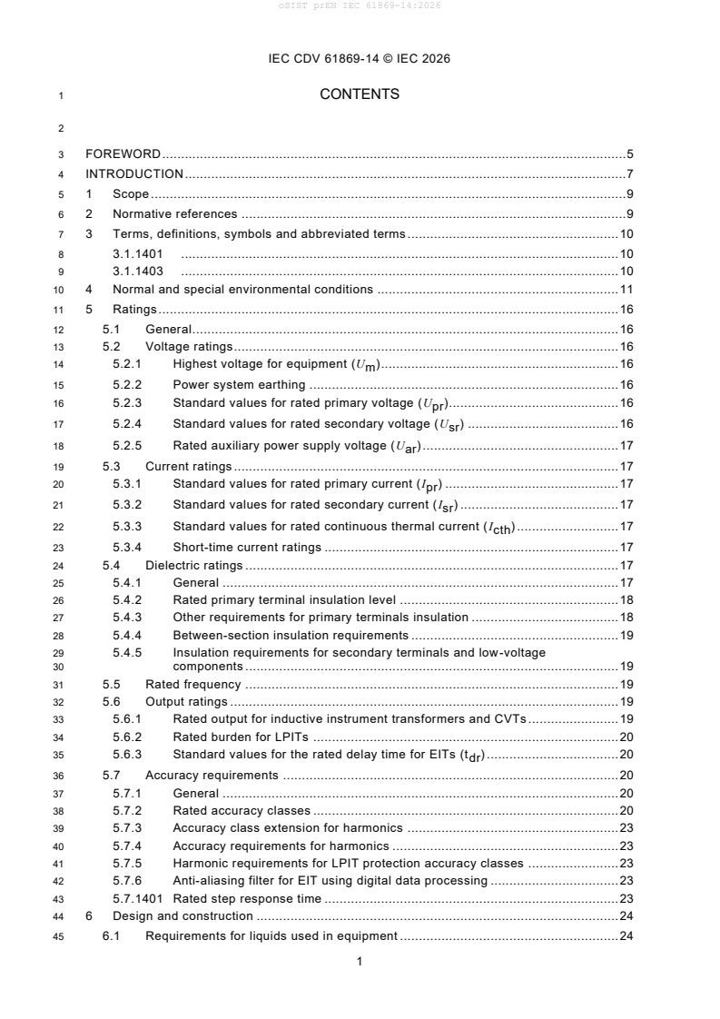
1 CONTENTS
3 FOREWORD . 5
4 INTRODUCTION . 7
5 1 Scope . 9
6 2 Normative references . 9
7 3 Terms, definitions, symbols and abbreviated terms . 10
8 3.1.1401 . 10
9 3.1.1403 . 10
10 4 Normal and special environmental conditions . 11
11 5 Ratings . 16
12 5.1 General . 16
13 5.2 Voltage ratings . 16
14 5.2.1 Highest voltage for equipment (U ) . 16
m
15 5.2.2 Power system earthing . 16
16 5.2.3 Standard values for rated primary voltage (U ) . 16
pr
17 5.2.4 Standard values for rated secondary voltage (U ) . 16
sr
18 5.2.5 Rated auxiliary power supply voltage (U ) . 17
ar
19 5.3 Current ratings . 17
20 5.3.1 Standard values for rated primary current (I ) . 17
pr
21 5.3.2 Standard values for rated secondary current (I ) . 17
sr
22 5.3.3 Standard values for rated continuous thermal current (I ) . 17
cth
23 5.3.4 Short-time current ratings . 17
24 5.4 Dielectric ratings . 17
25 5.4.1 General . 17
26 5.4.2 Rated primary terminal insulation level . 18
27 5.4.3 Other requirements for primary terminals insulation . 18
28 5.4.4 Between-section insulation requirements . 19
29 5.4.5 Insulation requirements for secondary terminals and low-voltage
30 components . 19
31 5.5 Rated frequency . 19
32 5.6 Output ratings . 19
33 5.6.1 Rated output for inductive instrument transformers and CVTs . 19
34 5.6.2 Rated burden for LPITs . 20
35 5.6.3 Standard values for the rated delay time for EITs (t ) . 20
dr
36 5.7 Accuracy requirements . 20
37 5.7.1 General . 20
38 5.7.2 Rated accuracy classes . 20
39 5.7.3 Accuracy class extension for harmonics . 23
40 5.7.4 Accuracy requirements for harmonics . 23
41 5.7.5 Harmonic requirements for LPIT protection accuracy classes . 23
42 5.7.6 Anti-aliasing filter for EIT using digital data processing . 23
43 5.7.1401 Rated step response time . 23
44 6 Design and construction . 24
45 6.1 Requirements for liquids used in equipment . 24
IEC CDV 61869-14 © IEC 2026
46 6.2 Requirements for gases used in equipment . 24
47 6.3 Requirements for solid materials used in equipment . 24
48 6.4 Requirements for temperature rise of parts and components . 24
49 6.5 Requirements for earthing of equipment . 24
50 6.6 Requirements for the external insulation . 24
51 6.6.1 Pollution . 24
52 6.6.2 Altitude . 24
53 6.7 Mechanical requirements . 25
54 6.8 Multiple chopped impulse on primary terminals . 25
55 6.9 Internal arc fault protection requirements . 25
56 6.10 Degrees of protection by enclosures . 25
57 6.11 Electromagnetic compatibility (EMC) . 25
58 6.11.1 General . 25
59 6.11.2 Requirement for immunity . 25
60 6.11.3 Requirement for emission . 26
61 6.11.4 Requirement for transmitted overvoltage (TOV) . 26
62 6.11.5 Requirement for radio interference voltage (RIV) . 26
63 6.12 Corrosion . 26
64 6.13 Markings . 26
65 6.13.1 General . 26
66 6.13.2 Terminal markings . 26
67 6.13.3 Rating plate markings . 27
68 6.14 Requirements for LPIT secondary terminal connection . 28
69 6.15 EIT secondary signal noise . 28
70 6.16 Fire hazard . 28
71 6.17 Pressure withstand of gas-filled enclosures . 28
72 6.18 Failure detection of EIT . 28
73 6.19 Operability . 28
74 6.20 Reliability and dependability of electronic part of EIT . 28
75 6.21 Vibration requirements . 28
76 6.22 Storage climatic conditions withstand capability . 28
77 7 Tests . 29
78 7.1 General . 29
79 7.1.1 Classification of tests . 29
80 7.1.2 List of tests . 29
81 7.1.3 Sequence of tests . 30
82 7.1.4 Testing conditions . 32
83 7.2 Type tests . 32
84 7.2.1 General . 32
85 7.2.2 Temperature rise test . 32
86 7.2.3 Impulse voltage withstand test on primary terminals . 32
87 7.2.4 Wet test for outdoor type transformers . 33
88 7.2.5 Electromagnetic compatibility (EMC) tests . 34
89 7.2.6 Test for accuracy . 34
90 7.2.7 Verification of the degree of protection by enclosures . 36
91 7.2.8 Enclosure tightness test at ambient temperature . 36
92 7.2.9 Proof test for the gas-filled enclosure . 36
93 7.2.10 Mechanical tests . 36
IEC CDV 61869-14 © IEC 2026
94 7.2.11 Voltage withstand test of low-voltage components and secondary
95 terminals . 36
96 7.2.12 Storage climate environmental tests . 36
97 7.2.13 Vibration test . 36
98 7.2.14 Durability of markings . 36
99 7.2.15 Tests for accuracy for harmonics . 36
100 7.2.16 Test for anti-aliasing . 37
101 7.2.1401 Polarity reversal test with partial discharge measurement . 37
102 7.2.1402 Measurement of the step response time . 39
103 7.2.1403 DC applied voltage withstand test . 40
104 7.3 Routine tests. 41
105 7.3.1 Power-frequency voltage withstand tests on primary terminals . 41
106 7.3.2 Partial discharge measurement . 41
107 7.3.3 Power-frequency voltage withstand tests between sections . 42
108 7.3.4 Power-frequency voltage withstand tests on secondary terminals . 42
109 7.3.5 Power-frequency voltage withstand test for low-voltage components . 42
110 7.3.6 Test for accuracy . 42
111 7.3.7 Verification of markings . 42
112 7.3.8 Enclosure tightness test at ambient temperature . 42
113 7.3.9 Pressure test for the gas-filled enclosure . 42
114 7.3.10 Measurement of capacitance and dielectric dissipation factor . 42
115 7.3.1401 DC applied voltage withstand test . 42
116 7.4 Special tests . 43
117 7.4.1 Multiple chopped impulse test on primary terminals . 43
118 7.4.2 Transmitted overvoltage test . 43
119 7.4.3 Internal arc fault test . 43
120 7.4.4 Enclosure tightness test at low and high temperatures . 43
121 7.4.5 Insulation resistance measurement on secondary terminals . 43
122 7.4.6 Corrosion test . 43
123 7.4.7 Fire hazard test . 44
124 7.4.8 Thermo-mechanical endurance test . 44
125 7.4.9 Vibration and shock tests . 44
126 7.4.10 Tests for accuracy versus harmonics . 45
127 7.4.11 Seismic qualification . 45
128 7.4.1401 Pollution tests . 45
129 7.5 Commissioning tests . 46
130 7.6 Sample tests . 46
131 8 Rules for transport, storage, erection, operation and maintenance . 47
132 9 Safety . 47
133 10 Influence of products on the natural environment . 47
134 Annex A (normative) Identification of test specimen . 48
135 Annex B (informative) Recommendation for contents of failure report . 49
136 Annex C (informative) Fire hazard . 50
137 Annex D (informative) Sample test . 51
138 Annex E (informative) Technique used in temperature rise test of transformers
139 to determine the thermal time constant by an experimental estimation. . 52
140 Annex F (informative) Guidance for the extension of validity of type test or
141 special tests of instrument transformers. 53
IEC CDV 61869-14 © IEC 2026
142 Annex G (informative) Guidance for the calculation of equivalent diameter in
143 case of irregular shape of insulating part . 54
144 Annex H (informative) Test circuits . 55
145 Annex I (informative) Seismic qualification of instrument transformers . 56
146 Annex 14A (informative) Equivalent thermal current in CTs for DC application . 57
147 14A.1 General . 57
148 14A.2 Current harmonic content . 57
149 14A.3 Losses in primary conductor due to harmonic content . 58
150 14A.4 Thermal test with AC current . 60
151 Annex 14B (normative) Composite AC/DC voltages . 61
152 14B.1 Composite AC/DC voltage descriptions . 61
153 14B.2 Example 1 – without 3PWM . 62
154 14B.3 Example 2 – with 3PWM . 62
155 14B.4 Conclusion . 64
156 Annex 14C (informative) Voltage definitions . 65
157 Bibliography . 66
159 Figure 1401 – Example of LCC scheme . 13
160 Figure 1402 – Typical scheme for VSC – symmetrical monopole . 15
161 Figure 1403 – Typical scheme for VSC – asymmetrical monopole or bipole . 15
162 Figure 1404 – Accuracy limits of a DC CT . 23
163 Figure 1405 – Polarity reversal test profile . 39
164 Figure 1406 – Measurement of the step response time . 41
165 Figure 14A.1 – Typical waveform of primary current for LCC applications . 58
166 Figure 14A.2 – The two terms that make up the total losses in the primary conductor . 60
167 Figure 14A.3 – Additional losses in conductors due to typical current harmonics . 61
168 Figure 14A.4 – Additional losses due to the use of AC current . 61
169 Figure 14B.1 – Example of an asymmetrical VSC converter . 62
170 Figure 14B.2 – Maximum peak voltage without 3PWM . 63
171 Figure 14B.3 – Both individual voltage curves with 3PWM . 64
172 Figure 14B.4 – Superimposed voltage curve with 3PWM, based on Figure 14B.3. 65
173 Figure 14C.1 – Voltage overview and definitions . 66
175 Table 1401 – Current and voltage in current transformers for LCC application . 14
176 Table 1402 – Current and voltage in current transformers for VSC application . 16
177 Table 4 – Partial discharge test voltages and permissible levels . 19
178 Table 1403 – Maximum values of tan . 20
179 Table 1404 – Limits of ratio error for DC CT (classes from 0,1 to 1) . 22
180 Table 1405 – Limits of ratio error for AC current measurement (classes from 0,1 to 1) . 23
181 Table 1406 – Accuracy class for higher frequencies. 24
182 Table 14 – Maximum static withstand loads . 26
183 Table 1407 – Markings of terminals . 28
184 Table 20 – List of tests. 30
185 Table 22 – Required routine tests . 32
186 Table 14A.1 – Typical harmonic current values (800 kV LCC) . 59
IEC CDV 61869-14 © IEC 2026
188 INTERNATIONAL ELECTROTECHNICAL COMMISSION
189 ____________
191 INSTRUMENT TRANSFORMERS –
193 Part 14: Additional requirements for current
194 transformers for DC applications
196 FOREWORD
197 1) The International Electrotechnical Commission (IEC) is a worldwide organization for standardization comprising
198 all national electrotechnical committees (IEC National Committees). The object of IEC is to promote international
199 co-operation on all questions concerning standardization in the electrical and electronic fields. To this end and
200 in addition to other activities, IEC publishes International Standards, Technical Specifications, Technical Reports,
201 Publicly Available Specifications (PAS) and Guides (hereafter referred to as “IEC Publication(s)”). Their
202 preparation is entrusted to technical committees; any IEC National Committee interested in the subject dealt with
203 may participate in this preparatory work. International, governmental and non-governmental organizations liaising
204 with the IEC also participate in this preparation. IEC collaborates closely with the International Organization for
205 Standardization (ISO) in accordance with conditions determined by agreement between the two organizations.
206 2) The formal decisions or agreements of IEC on technical matters express, as nearly as possible, an international
207 consensus of opinion on the relevant subjects since each technical committee has representation from all
208 interested IEC National Committees.
209 3) IEC Publications have the form of recommendations for international use and are accepted by IEC National
210 Committees in that sense. While all reasonable efforts are made to ensure that the technical content of IEC
211 Publications is accurate, IEC cannot be held responsible for the way in which they are used or for any
212 misinterpretation by any end user.
213 4) In order to promote international uniformity, IEC National Committees undertake to apply IEC Publications
214 transparently to the maximum extent possible in their national and regional publications. Any divergence between
215 any IEC Publication and the corresponding national or regional publication shall be clearly indicated in the latter.
216 5) IEC itself does not provide any attestation of conformity. Independent certification bodies provide conformity
217 assessment services and, in some areas, access to IEC marks of conformity. IEC is not responsible for any
218 services carried out by independent certification bodies.
219 6) All users should ensure that they have the latest edition of this publication.
220 7) No liability shall attach to IEC or its directors, employees, servants or agents including individual experts and
221 members of its technical committees and IEC National Committees for any personal injury, property damage or
222 other damage of any nature whatsoever, whether direct or indirect, or for costs (including legal fees) and
223 expenses arising out of the publication, use of, or reliance upon, this IEC Publication or any other IEC
224 Publications.
225 8) Attention is drawn to the Normative references cited in this publication. Use of the referenced publications is
226 indispensable for the correct application of this publication.
227 9) Attention is drawn to the possibility that some of the elements of this IEC Publication may be the subject of patent
228 rights. IEC shall not be held responsible for identifying any or all such patent rights.
229 IEC 61869-14 has been prepared by IEC technical committee 38: Instrument transformers. It is
230 an International Standard.
231 This second edition cancels and replaces the first edition published in 201 8. This edition
232 constitutes a technical revision.
233 The text of this standard is based on the following documents:
FDIS Report on voting
38/XX/FDIS 38/XX/RVD
235 Full information on the voting for the approval of this International Standard can be found in the
236 report on voting indicated in the above table.
237 This document has been drafted in accordance with the ISO/IEC Directives, Part 2.
IEC CDV 61869-14 © IEC 2026
238 This Part 14 is to be used in conjunction with, and is based on, IEC 61869-1:2023, General
239 requirements, – however the reader is encouraged to use the most recent editions.
240 This Part 14 follows the structure of IEC 61869-1:2023 and supplements or modifies the
241 corresponding clauses.
242 For additional clauses, subclauses, figures, tables, annexes or notes, the following numbering
243 system is used:
244 • clauses, subclauses, tables, figures and notes that are numbered starting from 1401 are
245 additional to those in Part 1;
246 • additional annexes are lettered 14A, 14B, etc.
247 A list of all parts in the IEC 61869 series, published under the general title Instrument
248 transformers, can be found on the IEC website: www.iec.ch
250 The committee has decided that the contents of this document will remain unchanged until the
251 stability date indicated on the IEC website under "http://webstore.iec.ch" in the data related to
252 the specific document. At this date, the document will be
253 • reconfirmed,
254 • withdrawn,
255 • replaced by a revised edition, or
256 • amended.
IMPORTANT – The 'colour inside' logo on the cover page of this publication indicates that it
contains colours which are considered to be useful for the correct understanding of its
contents. Users should therefore print this document using a colour printer.
IEC CDV 61869-14 © IEC 2026
260 INTRODUCTION
261 General
262 This document applies to current transformers intended to be used in DC applications with at
263 least one of the following functions:
264 • measure DC current (with significant harmonics);
265 • withstand DC voltage.
266 This document is the first revision of the standard IEC 61869-14, defining additional
267 requirements for current transformers for DC applications.
268 The main modifications of this revision are listed below:
269 • General
270 - adaption of the new structure and requirements of IEC 61869-1:2023, general
271 requirements for instrument transformers.
272 - transfer of the definitions to the TC 38 Glossary IEC 61869-99
273 - definitions related to composite AC and DC currents
274 - introduction of CT1 for VSC applications
275 • Ratings
276 - voltage ratings for composite AC and DC voltages including 3PWM
277 - rated delay time definition for point to point connections
278 - definition of fault analysis current factor K
FAC
279 - definition of accuracy requirements for AC current measurement
280 - definition of accuracy requirements for harmonics
281 - revised step response times
282 • Design and construction
283 - rating plate markings revised
284 • Tests
285 - Revised list of tests
286 - Table added indicating routine tests to be performed after a Type test
287 • Type tests
288 - composite AC and DC current: definition to perform tests separately in two tests
289 - step response time evaluation brought in line with definition in TC 38 Glossary IEC
290 61869-99
291 - DC applied voltage test introduced for equipment using for example an optical link
292 • Routine tests
293 - partial discharge measurement during DC applied voltage withstand test replaced by
294 verification of partial discharge level during repeated AC applied withstand test with
295 partial discharge measurement
296 - composite AC and DC current: definition to perform tests separately in two tests
297 • Special tests
298 - measurement of capacitance and dielectric dissipation factor eliminated, because test
299 is already routine test.
300 - even wetting DC voltage test eliminated, wet test performance, insulator performance
301 under wet condition is covered during type tests under 7.2.4.
IEC CDV 61869-14 © IEC 2026
302 - accuracy test on the composite signal is eliminated, it is covered during type tests under
303 7.2.15.
304 • new annexes:
305 - Annex A (normative): Identification of test specimen;
306 - Annex B (informative): Recommendation for contents of failure reports;
307 - Annex C (informative) Fire hazard;
308 - Annex D (informative): Sample test;
309 - Annex E (informative): Technique used in temperature rise test of transformers to
310 determine the thermal time constant by an experimental estimation;
311 - Annex F (informative): guidance for the extension of validity of type tests and special
312 tests;
313 - Annex G (informative): Guidance for the calculation of equivalent diameter in case of
314 irregular shape of insulating part;
315 - Annex H (informative): Test circuits
316 - Annex I (normative): seismic qualification of instrument transformers;
317 - Annex 14B (normative): Composite AC/DC voltages
318 Depending on the position of the current transformer on the DC system, different kinds of
319 applications exist, which are briefly described in 4.1401, together with the approximate voltage
320 or current wave shape.
IEC CDV 61869-14 © IEC 2026
323 INSTRUMENT TRANSFORMERS –
325 Part 14: Specific requirements for current
326 transformers for DC applications
328 1 Scope
329 This part of IEC 61869 provides all requirements specific to current transformers to be used in
330 DC applications (DC CTs), whatever the technology used. The output signal can be analogue
331 or digital. When it is analogue, it is available as low voltage representing the primary current.
332 It is applicable to newly manufactured current transformers used for measuring, protection
333 and/or control applications in power systems with a rated voltage above 1,5 kV DC.
334 The general configuration of a single-pole low-power instrument transformer is described in
335 Figure 1 of IEC 61869-1:2023.
336 NOTE A bushing type current transformer, although having no primary insulation level for itself is often placed on a system with
337 a nominal voltage > 1,5 kV DC and therefore falls within the scope of this document. Example: CT placed on an HV bushing or
338 a cable.
340 DC CT for railway applications are not part of this standard and are covered by IEC TC9.
341 2 Normative references
342 The following documents are referred to in the text in such a way that some or all of their content
343 constitutes requirements of this document. For dated references, only the edition cited applies.
344 For undated references, the latest edition of the referenced document (including any
345 amendments) applies.
346 Clause 2 of IEC 61869-1:2023 applies with the following additions:
347 IEC 60071-11:2022, Insulation coordination - Part 11: Definitions, principles and rules for HVDC
348 systems
349 IEC 60270:2025, High voltage test techniques – Partial discharge measurements
350 IEC TS 60815-4:2016, Selection and dimensioning of high-voltage insulators intended for use
351 in polluted conditions – Part 4: Insulators for DC systems
352 IEC TS 61245:2015, Artificial pollution tests on high-voltage ceramic and glass insulators to be
353 used on DC systems
354 IEC 61869-1:2023, Instrument transformers – Part 1: General requirements
355 IEC 61869-2, Instrument transformers – Part 2: Additional requirements for current transformers
356 IEC 61869-9:2016, Instrument transformers – Part 9: Digital interface for instrument
357 transformers
358 IEC 61869-99:2022, Instrument transformers – Part 99: Glossary
359 IEC/TR 61869-103:2012, Instrument transformers – The use of instrument transformers for
360 power quality measurements
IEC CDV 61869-14 © IEC 2026
361 IEC 62475 :2010, High-current test techniques – Definitions and requirements for test currents
362 and measuring systems
363 IEC TS 62271-5:2024, High-voltage switchgear and controlgear – Part5: Common specification
364 for direct current switchgear and controlgear
365 3 Terms, definitions, symbols and abbreviated terms
366 3.1 Terms and definitions
367 ISO and IEC maintain terminological databases for use in standardization at the following
368 addresses:
369 • IEC Electropedia: available at http://www.electropedia.org/;
370 • ISO Online browsing platform: available at http://www.iso.org/obp.
371 For the purposes of this document, the terms and definitions of IEC 61869-99 apply with the
372 following addition.
373 3.1.1401
374 Absolute error
375
A
376 error (expressed in A) that a current transformer introduces into the measurement, and which
377 arises from the fact that the actual transformation ratio is not equal to the rated transformation
378 ratio
379 Note 1 to entry: The absolute error is defined by the following formula:
380 = K U – I
A r s p
381 where
382 K is the rated transformation ratio in A/V;
r
383 I is the DC value of the actual primary current in steady state;
p
384 U is the DC value of the output voltage.
s
385 3.1.1402
386 fault analysis current factor
387 K
FAC
388 ratio of the maximum peak fault currents to be analysed to the rated primary current
̂
𝐼
𝑎𝑛𝑎𝑙𝑦𝑠𝑖𝑠
389 𝑘 =
𝐹𝐴𝐶
𝐼
𝑝𝑟
390 where
391 Î is the measured peak fault current to be analysed for converter protection, analysis with less stringent
analysis
392 accuracy requirements
393 3.1.1403
394 AC grid power frequency
395 f
rACgrid
397 Rated frequency of the AC grid to which the HVDC station is connected
IEC CDV 61869-14 © IEC 2026
399 3.2 Symbols and abbreviated terms
400 The table in 3.2 of IEC 61869-1:2023 is replaced by the following one:
CT current transformer
DC Direct Current
F mechanical load
rated AC grid power frequency
f
rAC
I rated continuous thermal current
cth
I rated primary current
pr
IT instrument transformer
K accuracy limit factor
ALF
K rated extended primary current factor
epr
K
fault analysis current factor
FAC
K rated transformation ratio
r
Z rated burden
br
t delay time
d
t
rated delay time
dr
T settling time
set
T step response time
sr
U auxiliary power supply voltage
ar
U DC system voltage
DC
U highest DC voltage of a system
DCmax
U voltage harmonic of frequency f
h h
U voltage harmonic with the highest amplitude
hAmax
U highest voltage for equipment
m
U rated secondary voltage
sr
ratio error
absolute error
A
3PWM Pulse width modulation with third harmonic, also known as third harmonic injection (THI)
401 4 Normal and special environmental conditions
402 Clause 4 of IEC 61869-1:2023 applies with the following addition.
403 4.1401 Operational environment and configurations of DC CT in Converter-based
404 systems
405 4.1401.1 Line-commutated converters (LCC)
406 Line-commutated converters (LCC) are based on thyristor converters (see Figure 1401). They
407 are characterized by a single direction of current flow, and a voltage polarity reversal possibility.
408 Significant voltage and current harmonics exist up to frequencies of about 3 kHz to 4 kHz.
IEC CDV 61869-14 © IEC 2026
412 Figure 1401 – Example of LCC scheme
413 We distinguish three main locations for DC CTs in LCC applications, covered in this standard:
414 • CT1: measurement of the current at the AC side of the converter;
415 • CT2: measurement of the current at the DC side of the converter;
416 • CT3: measurement of the current in the DC filter.
417 NOTE The numbering is for orientation purposes only.
418 Table 1401 gives an overview of the current and voltage waveshapes as well as the main
419 characteristics of the different applications of the CT.
IEC CDV 61869-14 © IEC 2026
422 Table 1401 – Current and voltage in current transformers for LCC application
Current Voltage Characteristics
CT1 AC current
AC voltage with DC offset
Large amount of current harmonics
Mainly for protection purposes
CT2 DC current
DC voltage stress with AC components
High-accuracy measurement
Harmonics measurement
Metering, control and protection
purposes
CT3 DC current = 0, but with AC components
DC voltage stress with AC components
Harmonics measurement
Mainly for protection purposes
424 4.1401.2 Voltage-source converters (VSC)
425 Voltage-source converters (VSC) are based on transistor converters. They are characterized
426 by a bi-directional current flow and a single voltage polarity. Voltage and current harmonics
427 exist up to frequencies of about 20 kHz.
428 Two variants of VSC schemes exist: symmetrical monopoles (using one single converter) and
429 asymmetrical monopole or bipole (with one converter for each polarity).
430 Both schemes are shown in Figure 1402 and Figure 1403.
IEC CDV 61869-14 © IEC 2026
434 Figure 1402 – Typical scheme for VSC – symmetrical monopole
438 Figure 1403 – Typical scheme for VSC – asymmetrical monopole or bipole
439 We distinguish four main locations for DC CTs in VSC applications covered in this standard:
440 • CT1: measurement of the current at the AC side of the converter;
441 • CT4: measurement of the current in the transistor branches of the converter.
442 The CT can be placed before (CT4a) or after the transistor branch (CT4b);
443 • CT2: measurement of the current at the DC side of the converter;
444 • CT3: measurement of the current in the DC filter (not always present in this scheme).
445 NOTE The numbering is for orientation purposes only.
446 Table 1402 gives an overview of the current and voltage waveshapes as well as the main
447 characteristics of the different applications of the CT.
IEC CDV 61869-14 © IEC 2026
448 Table 1402 – Current and voltage in current transformers for VSC application
Current Voltage Characteristics
I
CT1 AC current with very small
DC component
AC voltage with DC offset
0 High-accuracy
measurement
t
Short step response time
CT2 DC current
DC voltage
High accuracy
measurement
Harmonics measurement
Metering, control and
protection purposes
Short step response time
CT3 DC current = 0
DC voltage stress with AC
components
Harmonics measurement
Mainly for protection
purposes
CT4a Symmetrical monopole: AC current with DC
component
Pure AC voltage or with
DC offset
High-accuracy
measurement
Short step response time
Asymmetrical monopoles /
bipoles:
CT4b DC voltage stress
AC current with DC
component
High-accuracy
measurement
Short step response time
450 Note VSC converter considered in this context are based on Multi Module Converter (MMC) technology.
IEC CDV 61869-14 © IEC 2026
451 5 Ratings
452 5.1 General
453 Subclause 5.1 of IEC 61869-1:2023 is replaced by the following one:
454 The applicable ratings of DC current transformers, including their auxiliary equipment, shall be
455 selected from the following ones (as applicable):
456 a) highest voltage for equipment (U );
m
457 b
...