

prEN IEC 61869-15:2026
(Main)Instrument transformers - Part 15: Additional requirements for voltage transformers for DC applications
- Status
- Not Published
- Publication Date
- 06-Apr-2028
- Technical Committee
- CLC/TC 38 - Instrument transformers
- Current Stage
- 4020 - Enquiry circulated - Enquiry
- Start Date
- 30-Oct-2026
- Due Date
- 30-Jun-2025
- Completion Date
- 30-Oct-2026

prEN IEC 61869-15:2026 is a draft IEC/CENELEC standard from IEC TC 38 for instrument transformers. It specifies additional requirements for voltage transformers (VT) used in DC applications, including measuring, protection and control in power systems above 1.5 kV DC. The document is intended for manufacturers, test laboratories, and purchasers who need to define ratings, insulation, accuracy, markings, and test methods for DC VTs.
What does prEN IEC 61869-15:2026 specify?
prEN IEC 61869-15:2026 covers voltage transformers for DC applications, whatever the technology used, and allows analogue or digital output signals. It applies to newly manufactured VTs for measuring, protection and/or control in DC power systems above 1.5 kV DC.
prEN IEC 61869-15:2026 follows the structure of IEC 61869-1:2023 and then supplements or modifies the corresponding clauses. Additional clauses, figures, tables and notes are numbered from 1501, and additional annexes are numbered 15A, 15B, and so on.
It includes general requirements, ratings, design and construction, tests, transport and storage, safety, and environmental influence.
| Annex | What it covers |
|---|---|
| Annex A | Identification of test specimen |
| Annex B | Recommended contents of failure reports |
| Annex C | Fire hazard |
| Annex D | Sample test |
| Annex E | Temperature rise test technique and thermal time constant estimation |
| Annex F | Extension of validity of type tests or special tests |
| Annex G | Equivalent diameter guidance for irregular insulating parts |
| Annex H | Test circuits |
| Annex I | Seismic qualification of instrument transformers |
| Annex 15A | Composite AC/DC voltages |
| Annex 15B | Voltage definitions |
What are the key requirements of prEN IEC 61869-15:2026?
Ratings are chosen for the actual DC system
prEN IEC 61869-15:2026 requires the purchaser to select the applicable ratings from a defined list in Clause 5.1. These include highest voltage for equipment, rated primary voltage, rated delay time, rated secondary voltage, insulation level, rated burden, rated accuracy class, and rated step response time.
In practice, this means the VT is not specified from one fixed set of values. The ratings must match the DC system, the converter arrangement, and the intended use for measurement, protection, or control.
Primary and secondary voltage values are handled differently
prEN IEC 61869-15:2026 states that there are no standard values for rated primary voltage, but it gives standard values for analogue secondary DC output of 5 V, 10 V, 50 V, and 100 V in Clause 5.2. It also identifies isolated neutral and solidly earthed neutral as the DC power system earthing types.
For a buyer or designer, this means the primary side is coordinated to the HVDC system, while the secondary side is chosen from the standard outputs used by meters, relays, or control equipment.
Insulation is based on DC system voltage and converter type
Clause 5.4 ties the rated primary terminal insulation level to the highest voltage for equipment, and it uses IEC 60071-11:2022 for typical DC voltages and insulation levels. For DC VTs with significant AC voltage, the document adds a combined AC/DC insulation approach and points to Annex 15A and Annex 15B for composite voltage definitions.
Clause 5.4.3 also sets partial discharge limits in Table 4, and Clause 5.4.3.2 requires chopped lightning impulse withstand for VTs with U >= 20 kV, other than GIS devices. In practice, the insulation design has to match both steady DC stress and the relevant impulse and partial discharge performance.
Accuracy is defined separately for DC, AC components, harmonics, and dynamics
Clause 5.7 gives the accuracy classes 0.1, 0.2, 0.5, 1, and 3. It sets ratio error limits for the DC component in Table 1503, and for VTs measuring superposed AC and DC voltage it sets separate limits for the AC component in Table 1504.
The document also covers harmonics and ripple, and it defines standard rated step response times of 25 µs, 100 µs, 250 µs, and 1 ms. For digital output, the rated delay time is zero because the merging unit provides the time reference. This matters because the VT must be accurate not only at steady state, but also when the waveform contains harmonics or changes quickly.
Construction and markings are adapted to DC VTs
Clause 6 covers pollution, altitude, mechanical load, EMC, corrosion, fire hazard, vibration, storage conditions, and markings. For external insulation at U >= 20 kV, creepage distances are based on the DC unified specific creepage distance (RUSCDdc), and indoor VTs use a minimum RUSCDdc of 14 mm/kV.
Clause 6.11 applies EMC requirements to electronic DC VTs and adds radio interference voltage requirements for VTs at or above 100 kV installed in air-insulated substations. Clause 6.13 requires terminal markings, rating plate markings, and, where applicable, separate marking of AC and DC accuracy. Secondary connection cables also need serial-number identification.
Tests verify design, routine production, and special operating stresses
Clause 7 sets out type tests, routine tests, special tests, commissioning tests, and sample tests. The list includes temperature rise, impulse withstand, wet testing for outdoor types, EMC, accuracy, enclosure protection, gas enclosure tests, vibration, harmonics, anti-aliasing, and seismic qualification.
Several DC-specific tests are added or revised in practice: the DC applied voltage withstand test, the polarity reversal test with partial discharge measurement for certain high-voltage LCC or full bridge MMC applications, the step response time measurement, the impact of electric field at rated frequency, pollution tests, and the accuracy stability stress test. This is the part of the document that test houses use to prove a design and that buyers use to specify acceptance.
What terms does prEN IEC 61869-15:2026 define?
- DC VT - A voltage transformer for DC applications, used for measurement, protection, or control on DC systems.
- VT1 - A DC VT used where a significant AC voltage is superposed on the DC voltage.
- LCC - Line-commutated converters, based on thyristor converters with single-direction current flow and possible voltage polarity reversal.
- VSC - Voltage-source converters, based on transistor converters with bidirectional current flow and a single voltage polarity.
- 3PWM - Pulse width modulation with third harmonic, also called third harmonic injection (THI).
- LPIT - Low-power instrument transformer, the general class used for low-power output signals.
- EIT - Electronic instrument transformer, used where the measuring chain includes electronic processing.
- Absolute error - The voltage error caused when the actual transformation ratio differs from the rated transformation ratio.
Who uses prEN IEC 61869-15:2026?
prEN IEC 61869-15:2026 is used by manufacturers of DC voltage transformers, HVDC system designers, test laboratories, and purchasers who specify instrument transformer performance. It is also relevant to utilities and engineering teams working on electricity transmission and distribution, especially HVDC converter stations, air-insulated substations, GIS applications, and protection, metering, and control systems.
The document is most useful when a project needs to choose the transformer rating, define insulation coordination, check accuracy under DC and mixed AC/DC conditions, or plan type and routine testing.
What changed in prEN IEC 61869-15:2026 from the previous edition?
prEN IEC 61869-15:2026 cancels and replaces the first edition published in 2018 and is described as a technical revision. The introduction states these main changes:
- alignment with the structure and requirements of IEC 61869-1:2023
- transfer of definitions to IEC 61869-99
- new definitions related to composite AC and DC currents
- introduction of VT1 for VSC applications
- added voltage ratings for composite AC/DC voltages, including 3PWM
- added rated delay time definition for point-to-point connections
- revised accuracy requirements for AC voltage measurement and harmonics
- revised step response times
- revised rating plate markings
- revised test list and a table of routine tests to be performed after type testing
- separate testing approach for composite AC/DC voltage
- improved low-voltage terminal withstand test
- added test for impact of external electric field
- revised routine partial discharge approach
- removal or renaming of several special tests and annex updates
Which standards are used with prEN IEC 61869-15:2026?
- IEC 61869-1:2023 - The base standard for general requirements; prEN IEC 61869-15:2026 follows its structure and modifies selected clauses.
- IEC 61869-9:2016 - Used for digital output arrangements and digital interface-related accuracy testing.
- IEC 61869-99:2022 - Provides the glossary used for the document’s terminology.
- IEC 60071-11:2022 - Supplies HVDC insulation coordination definitions, principles, and typical voltage and insulation level information.
- IEC 60270:2025 - Defines partial discharge measurement methods used in the tests.
- IEC TS 60815-4:2016 - Used for selecting and dimensioning insulators in polluted DC conditions.
- IEC TS 61245:2015 - Provides artificial pollution test methods for DC systems.
What does the prEN IEC 61869-15:2026 document contain?
prEN IEC 61869-15:2026 contains tables for DC system voltages, accuracy limits, markings, test lists, routine test sequences, and test setup distances. It also contains figures for LCC and VSC schemes, composite AC/DC voltage behaviour, accuracy limits, polarity reversal testing, step response measurement, LPVT test arrangements, and voltage definitions.
The document gives formulas and procedures for insulation coordination, DC applied voltage withstand, step response time, resistance-based ratio checks, and composite AC/DC voltage rating. It is written for design work, type testing, routine production testing, commissioning, and special qualification tests.
Relations
- Effective Date
- 06-Aug-2024
Get Certified
Connect with accredited certification bodies for this standard

BSMI (Bureau of Standards, Metrology and Inspection)
Taiwan's standards and inspection authority.
Sponsored listings
Frequently Asked Questions
prEN IEC 61869-15:2026 is a draft published by CLC. Its full title is "Instrument transformers - Part 15: Additional requirements for voltage transformers for DC applications". This standard covers: Instrument transformers - Part 15: Additional requirements for voltage transformers for DC applications
Instrument transformers - Part 15: Additional requirements for voltage transformers for DC applications
prEN IEC 61869-15:2026 is classified under the following ICS (International Classification for Standards) categories: 17.220.20 - Measurement of electrical and magnetic quantities. The ICS classification helps identify the subject area and facilitates finding related standards.
prEN IEC 61869-15:2026 has the following relationships with other standards: It is inter standard links to EN IEC 61869-15:2019. Understanding these relationships helps ensure you are using the most current and applicable version of the standard.
prEN IEC 61869-15:2026 is available in PDF format for immediate download after purchase. The document can be added to your cart and obtained through the secure checkout process. Digital delivery ensures instant access to the complete standard document.
Standards Content (Sample)
SLOVENSKI STANDARD
01-december-2026
Instrumentni transformatorji - 15. del: Dodatne zahteve za napetostne
transformatorje za enosmerne aplikacije
Instrument transformers - Part 15: Additional requirements for voltage transformers for
DC applications
Messwandler - Teil 15: Zusätzliche Anforderungen an Spannungswandler für
Gleichstromanwendungen
Transformateurs de mesure - Partie 15: Exigences supplémentaires concernant les
transformateurs de tension pour application en courant continu
Ta slovenski standard je istoveten z: prEN IEC 61869-15:2026
ICS:
17.220.20 Merjenje električnih in Measurement of electrical
magnetnih veličin and magnetic quantities
2003-01.Slovenski inštitut za standardizacijo. Razmnoževanje celote ali delov tega standarda ni dovoljeno.
38/868/CDV
COMMITTEE DRAFT FOR VOTE (CDV)
PROJECT NUMBER:
IEC 61869-15 ED2
DATE OF CIRCULATION: CLOSING DATE FOR VOTING:
2026-10-30 2027-01-22
SUPERSEDES DOCUMENTS:
38/849/CD, 38/856A/CC
IEC TC 38 : INSTRUMENT TRANSFORMERS
SECRETARIAT: SECRETARY:
Italy Mr Filippo Frugoni
OF INTEREST TO THE FOLLOWING COMMITTEES: HORIZONTAL FUNCTION(S):
TC 13,TC 33,TC 57,SC 77A,TC 85,TC 95,TC 115
ASPECTS CONCERNED:
Electricity transmission and distribution,Electromagnetic Compatibility
SUBMITTED FOR CENELEC PARALLEL VOTING NOT SUBMITTED FOR CENELEC PARALLEL VOTING
Attention IEC-CENELEC parallel voting
The attention of IEC National Committees, members of
CENELEC, is drawn to the fact that this Committee Draft for
Vote (CDV) is submitted for parallel voting.
The CENELEC members are invited to vote through the
CENELEC online voting system.
This document is still under study and subject to change. It should not be used for reference purposes.
Recipients of this document are invited to submit, with their comments, notification of any relevant patent rights of which
they are aware and to provide supporting documentation.
Recipients of this document are invited to submit, with their comments, notification of any relevant “In Some Countries”
clauses to be included should this proposal proceed. Recipients are reminded that the CDV stage is the final stage for
submitting ISC clauses. (SEE AC/22/2007 OR NEW GUIDANCE DOC).
TITLE:
Instrument transformers - Part 15: Additional requirements for voltage transformers for DC
applications
PROPOSED STABILITY DATE: 2032
NOTE FROM TC/SC OFFICERS:
electronic file, to make a copy and to print out the content for the sole purpose of preparing National Committee positions.
You may not copy or "mirror" the file or printed version of the document, or any part of it, for any other purpose without
permission in writing from IEC.
IEC CDV 61869-15 © IEC 2026
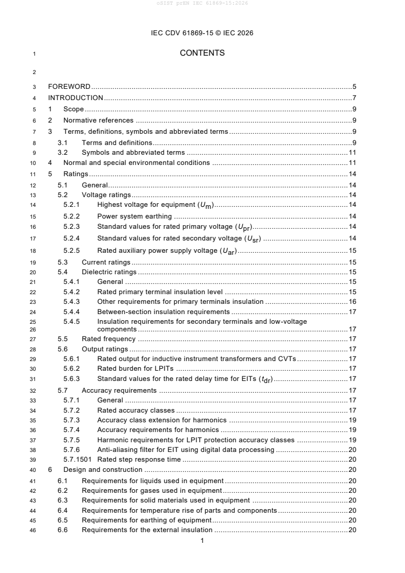
1 CONTENTS
3 FOREWORD . 5
4 INTRODUCTION . 7
5 1 Scope . 9
6 2 Normative references . 9
7 3 Terms, definitions, symbols and abbreviated terms . 9
8 3.1 Terms and definitions . 9
9 3.2 Symbols and abbreviated terms . 11
10 4 Normal and special environmental conditions . 11
11 5 Ratings . 14
12 5.1 General . 14
13 5.2 Voltage ratings . 14
14 5.2.1 Highest voltage for equipment (U ) . 14
m
15 5.2.2 Power system earthing . 14
16 5.2.3 Standard values for rated primary voltage (U ) . 14
pr
17 5.2.4 Standard values for rated secondary voltage (U ) . 14
sr
18 5.2.5 Rated auxiliary power supply voltage (U ) . 15
ar
19 5.3 Current ratings . 15
20 5.4 Dielectric ratings . 15
21 5.4.1 General . 15
22 5.4.2 Rated primary terminal insulation level . 15
23 5.4.3 Other requirements for primary terminals insulation . 16
24 5.4.4 Between-section insulation requirements . 17
25 5.4.5 Insulation requirements for secondary terminals and low-voltage
26 components . 17
27 5.5 Rated frequency . 17
28 5.6 Output ratings . 17
29 5.6.1 Rated output for inductive instrument transformers and CVTs . 17
30 5.6.2 Rated burden for LPITs . 17
31 5.6.3 Standard values for the rated delay time for EITs (t ) . 17
dr
32 5.7 Accuracy requirements . 17
33 5.7.1 General . 17
34 5.7.2 Rated accuracy classes . 17
35 5.7.3 Accuracy class extension for harmonics . 19
36 5.7.4 Accuracy requirements for harmonics . 19
37 5.7.5 Harmonic requirements for LPIT protection accuracy classes . 19
38 5.7.6 Anti-aliasing filter for EIT using digital data processing . 20
39 5.7.1501 Rated step response time . 20
40 6 Design and construction . 20
41 6.1 Requirements for liquids used in equipment . 20
42 6.2 Requirements for gases used in equipment . 20
43 6.3 Requirements for solid materials used in equipment . 20
44 6.4 Requirements for temperature rise of parts and components . 20
45 6.5 Requirements for earthing of equipment . 20
46 6.6 Requirements for the external insulation . 20
IEC CDV 61869-15 © IEC 2026
47 6.6.1 Pollution . 20
48 6.6.2 Altitude . 21
49 6.7 Mechanical requirements . 21
50 6.8 Multiple chopped impulse on primary terminals . 21
51 6.9 Internal arc fault protection requirements . 21
52 6.10 Degrees of protection by enclosures . 21
53 6.11 Electromagnetic compatibility (EMC) . 21
54 6.11.1 General . 21
55 6.11.2 Requirement for immunity . 21
56 6.11.3 Requirement for emission . 21
57 6.11.4 Requirement for transmitted overvoltage (TOV) . 21
58 6.11.5 Requirement for radio interference voltage (RIV) . 22
59 6.11.1501 Impact of electric field at rated frequency from other phases . 22
60 6.12 Corrosion . 22
61 6.13 Markings . 22
62 6.13.1 General . 22
63 6.13.2 Terminal markings . 22
64 6.13.3 Rating plate markings . 23
65 6.13.1501 Rating plate markings for cables . 25
66 6.14 Requirements for LPIT secondary terminal connection . 25
67 6.15 EIT secondary signal noise . 25
68 6.16 Fire hazard . 25
69 6.17 Pressure withstand of gas-filled enclosures . 25
70 6.18 Failure detection of EIT . 25
71 6.19 Operability . 25
72 6.20 Reliability and dependability of electronic part of EIT . 26
73 6.21 Vibration requirements . 26
74 6.22 Storage climatic conditions withstand capability . 26
75 7 Tests . 26
76 7.1 General . 26
77 7.1.1 Classification of tests . 26
78 7.1.2 List of tests . 26
79 7.1.3 Sequence of tests . 27
80 7.1.4 Testing conditions . 29
81 7.2 Type tests . 29
82 7.2.1 General . 29
83 7.2.2 Temperature rise test . 29
84 7.2.3 Impulse voltage withstand test on primary terminals . 29
85 7.2.4 Wet test for outdoor type transformers . 30
86 7.2.5 Electromagnetic compatibility (EMC) tests . 31
87 7.2.6 Test for accuracy . 31
88 7.2.7 Verification of the degree of protection by enclosures . 33
89 7.2.8 Enclosure tightness test at ambient temperature . 33
90 7.2.9 Proof test for the gas-filled enclosure . 33
91 7.2.10 Mechanical tests . 33
92 7.2.11 Voltage withstand test of low-voltage components and secondary
93 terminals . 33
94 7.2.12 Storage climate environmental tests . 34
95 7.2.13 Vibration test . 35
IEC CDV 61869-15 © IEC 2026
96 7.2.14 Durability of markings . 35
97 7.2.15 Tests for accuracy for harmonics . 35
98 7.2.16 Test for anti-aliasing . 35
99 7.2.1501 Polarity reversal test with partial discharge measurement . 35
100 7.2.1502 Measurement of the step response time . 36
101 7.2.1503 Test for impact of electric field at rated frequency . 37
102 7.3 Routine tests. 39
103 7.3.1 Power-frequency voltage withstand tests on primary terminals . 39
104 7.3.2 Partial discharge measurement . 40
105 7.3.3 Power-frequency voltage withstand tests between sections . 40
106 7.3.4 Power-frequency voltage withstand tests on secondary terminals . 40
107 7.3.5 Power-frequency voltage withstand test for low-voltage components . 40
108 7.3.6 Test for accuracy . 40
109 7.3.7 Verification of markings . 41
110 7.3.8 Enclosure tightness test at ambient temperature . 41
111 7.3.9 Pressure test for the gas-filled enclosure . 41
112 7.3.10 Measurement of capacitance and dielectric dissipation factor . 41
113 7.3.1501 DC applied voltage withstand test . 41
114 7.3.1502 Resistance measurement . 42
115 7.4 Special tests . 42
116 7.4.1 Multiple chopped impulse test on primary terminals . 42
117 7.4.2 Transmitted overvoltage test . 42
118 7.4.3 Internal arc fault test . 42
119 7.4.4 Enclosure tightness test at low and high temperatures . 42
120 7.4.5 Insulation resistance measurement on secondary terminals . 42
121 7.4.6 Corrosion test . 42
122 7.4.7 Fire hazard test . 42
123 7.4.8 Thermo-mechanical endurance test . 42
124 7.4.9 Vibration and shock tests . 43
125 7.4.10 Tests for accuracy versus harmonics . 43
126 7.4.11 Seismic qualification . 43
127 7.4.1501 Pollution tests . 43
128 7.4.1502 Accuracy stability stress test. 44
129 7.5 Commissioning tests . 44
130 7.6 Sample tests . 44
131 8 Rules for transport, storage, erection, operation and maintenance . 44
132 9 Safety . 44
133 10 Influence of products on the natural environment . 44
134 Annex A (normative) Identification of test specimen . 45
135 Annex B (informative) Recommendation for contents of failure report . 46
136 Annex C (informative) Fire hazard . 47
137 Annex D (informative) Sample test . 48
138 Annex E (informative) Technique used in temperature rise test of transformers to
139 determine the thermal time constant by an experimental estimation. . 49
140 Annex F (informative) Guidance for the extension of validity of type test or special
141 tests of instrument transformers . 50
142 Annex G (informative) Guidance for the calculation of equivalent diameter in case of
143 irregular shape of insulating part . 51
IEC CDV 61869-15 © IEC 2026
144 Annex H (informative) Test circuits . 52
145 Annex I (normative) Seismic qualification of instrument transformers . 53
146 Annex 15A (normative) Composite AC/DC voltages . 54
147 15A.1 Composite AC/DC voltage descriptions . 54
148 15A.2 Example 1 – without 3PWM . 55
149 15A.3 Example 2 – with 3PWM . 55
150 15A.4 Conclusion . 57
151 Annex 15B (informative) Voltage definitions. 58
152 Bibliography . 59
154 Figure 1501 – Example of LCC scheme . 13
155 Figure 1502 – Typical scheme for VSC – symmetrical monopole . 14
156 Figure 1503 – Typical scheme for VSC – asymmetrical monopole or bipole . 14
157 Figure 1504 – Accuracy limits of a DC VT . 19
158 Figure 1505 – RC divider with low-voltage part outside the main housing . 34
159 Figure 1506 – Connection for voltage withstand test of the external low voltage part of
160 a DC VT . 35
161 Figure 1507 – Polarity reversal test profile . 36
162 Figure 1508– Measurement of the step response time . 38
163 Figure 1509– Test setup for LPVT used in air-insulated substations . 39
164 Figure 15A.1 – Example of an asymmetrical VSC converter . 55
165 Figure 15A.2 – Maximum peak voltage without 3PWM . 56
166 Figure 15A.3 – Both individual voltage curves with 3PWM . 57
167 Figure 15A.4 – Superimposed voltage curve with 3PWM, based on Figure 15A.3. 58
168 Figure 15B.1 – Voltage overview and definitions . 59
170 Table 1501 – Voltage on DC VT´s for LCC application . 13
171 Table 1502 – Voltage on DC VT´s for VSC application . 14
172 Table 4 – Partial discharge test voltages and permissible levels . 17
173 Table 1503 – Limits of ratio error for DC VT (classes from 0,1 to 3) . 19
174 Table 1504 – Limits of ratio error for AC component of superposed AC and DC
175 voltages . 20
176 Table 14– Maximum static withstand loads . 22
177 Table 1505 – Markings of terminals . 24
178 Table 1506 – Rating plate marking for common rating plate . 25
179 Table 1507 – Rating plate marking for each secondary converter . 26
180 Table 1508 – Rating plate marking for auxiliary power supply . 26
181 Table 20 – List of tests. 27
182 Table 22 – Required routine tests . 29
183 Table 1509 – Test setup distances . 39
IEC CDV 61869-15 © IEC 2026
186 INTERNATIONAL ELECTROTECHNICAL COMMISSION
187 ____________
189 INSTRUMENT TRANSFORMERS –
191 Part 15: Additional requirements for voltage
192 transformers for DC applications
194 FOREWORD
195 1) The International Electrotechnical Commission (IEC) is a worldwide organization for standardization comprising
196 all national electrotechnical committees (IEC National Committees). The object of IEC is to promote international
197 co-operation on all questions concerning standardization in the electrical and electronic fields. To this end and
198 in addition to other activities, IEC publishes International Standards, Technical Specifications, Technical Reports,
199 Publicly Available Specifications (PAS) and Guides (hereafter referred to as “IEC Publication(s)”). Their
200 preparation is entrusted to technical committees; any IEC National Committee interested in the subject dealt with
201 may participate in this preparatory work. International, governmental and non-governmental organizations liaising
202 with the IEC also participate in this preparation. IEC collaborates closely with the International Organization for
203 Standardization (ISO) in accordance with conditions determined by agreement between the two organizations.
204 2) The formal decisions or agreements of IEC on technical matters express, as nearly as possible, an international
205 consensus of opinion on the relevant subjects since each technical committee has representation from all
206 interested IEC National Committees.
207 3) IEC Publications have the form of recommendations for international use and are accepted by IEC National
208 Committees in that sense. While all reasonable efforts are made to ensure that the technical content of IEC
209 Publications is accurate, IEC cannot be held responsible for the way in which they are used or for any
210 misinterpretation by any end user.
211 4) In order to promote international uniformity, IEC National Committees undertake to apply IEC Publications
212 transparently to the maximum extent possible in their national and regional publications. Any divergence between
213 any IEC Publication and the corresponding national or regional publication shall be clearly indicated in the latter.
214 5) IEC itself does not provide any attestation of conformity. Independent certification bodies provide conformity
215 assessment services and, in some areas, access to IEC marks of conformity. IEC is not responsible for any
216 services carried out by independent certification bodies.
217 6) All users should ensure that they have the latest edition of this publication.
218 7) No liability shall attach to IEC or its directors, employees, servants or agents including individual experts and
219 members of its technical committees and IEC National Committees for any personal injury, property damage or
220 other damage of any nature whatsoever, whether direct or indirect, or for costs (including legal fees) and
221 expenses arising out of the publication, use of, or reliance upon, this IEC Publication or any other IEC
222 Publications.
223 8) Attention is drawn to the Normative references cited in this publication. Use of the referenced publications is
224 indispensable for the correct application of this publication.
225 9) Attention is drawn to the possibility that some of the elements of this IEC Publication may be the subject of patent
226 rights. IEC shall not be held responsible for identifying any or all such patent rights.
227 IEC 61869-15 has been prepared by IEC technical committee 38: Instrument transformers. It
228 is an international standard.
229 This second edition cancels and replaces the first edition published in 2018. This edition
230 constitutes a technical revision.
231 The text of this standard is based on the following documents:
FDIS Report on voting
38/XX/FDIS 38/XX/RVD
233 Full information on the voting for the approval of this International Standard can be found in the
234 report on voting indicated in the above table.
235 This document has been drafted in accordance with the ISO/IEC Directives, Part 2.
IEC CDV 61869-15 © IEC 2026
236 This Part 15 is to be used in conjunction with, and is based on, IEC 61869-1:2023, General
237 requirements, – however the reader is encouraged to use the most recent editions.
238 This Part 15 follows the structure of IEC 61869-1:2023 and supplements or modifies the
239 corresponding clauses.
240 For additional clauses, subclauses, figures, tables, annexes or notes, the following numbering
241 system is used:
242 • clauses, subclauses, tables, figures and notes that are numbered starting from 1501 are
243 additional to those in Part 1;
244 • additional annexes are lettered 15A, 15B, etc.
245 A list of all parts in the IEC 61869 series, published under the general title Instrument
246 transformers, can be found on the IEC website: www.iec.ch.
248 The committee has decided that the contents of this document will remain unchanged until the
249 stability date indicated on the IEC website under "http://webstore.iec.ch" in the data related to
250 the specific document. At this date, the document will be
251 • reconfirmed,
252 • withdrawn,
253 • replaced by a revised edition, or
254 • amended.
IMPORTANT – The 'colour inside' logo on the cover page of this publication indicates
that it contains colours which are considered to be useful for the correct understanding
of its contents. Users should therefore print this document using a colour printer.
IEC CDV 61869-15 © IEC 2026
258 INTRODUCTION
259 General
260 This document applies to voltage transformers (VT) intended to be used in DC applications with
261 at least one of the following functions:
262 measure DC voltage (with significant harmonics);
263 withstand DC voltage.
264 This document is the first revision of the standard IEC 61869-15, defining additional
265 requirements for voltage transformers for DC applications.
266 The main modifications of this revision are listed below:
267 • General
268 - adaption of the new structure and requirements of IEC 61869-1:2023, general
269 requirements for instrument transformers.
270 - transfer of the definitions to the TC 38 Glossary IEC 61869-99
271 - definitions related to composite AC and DC currents
272 - introduction of VT1 for VSC applications
273 • Ratings
274 - voltage ratings for composite AC and DC voltages including 3PWM
275 - rated delay time definition for point to point connections
276 - definition of accuracy requirements for AC voltage measurement
277 - definition of accuracy requirements for harmonics
278 - revised step response times
279 • Design and construction
280 - rating plate markings revised
281 • Tests
282 - Revised list of tests
283 - Table added indicating routine tests to be performed after a Type test
284 • Type tests
285 - composite AC and DC voltage: definition to perform tests separately in two tests
286 - voltage withstand test for low voltage terminals improved
287 - step response time evaluation brought in line with definition in TC 38 Glossary IEC
288 61869-99
289 - test for impact of external field for DC VT measuring AC components added
290 • Routine tests
291 - partial discharge measurement during DC applied voltage withstand test replaced by
292 verification of partial discharge level during repeated AC applied withstand test with
293 partial discharge measurement
294 - composite AC and DC voltage: definition to perform tests separately in two tests
295 • Special tests
IEC CDV 61869-15 © IEC 2026
296 - measurement of capacitance and dielectric dissipation factor eliminated, because test
297 is already routine test.
298 - even wetting DC voltage test eliminated, wet test performance, insulator performance
299 under wet condition is covered during type tests under 7.2.4.
300 - accuracy test on the composite signal is eliminated, it is covered during type tests
301 under 7.2.15.
302 - subclause 7.4.1501.2 renamed to Wet DC voltage test
303 - subclause 7.4.1502 deleted
304 - subclause 7.4.1503, now 7.4.1502 renamed to Accuracy stability stress test
305 i) new annexes:
306 - Annex A (normative): Identification of test specimen;
307 - Annex B (informative): Recommendation for contents of failure reports;
308 - Annex C (informative) Fire hazard;
309 - Annex D (informative): Sample test;
310 - Annex E (informative): Technique used in temperature rise test of transformers to
311 determine the thermal time constant by an experimental estimation;
312 - Annex F (informative): guidance for the extension of validity of type tests and special
313 tests;
314 - Annex G (informative): Guidance for the calculation of equivalent diameter in case of
315 irregular shape of insulating part;
316 - Annex H (informative): Test circuits
317 - Annex I (normative): seismic qualification of instrument transformers;
318 - Annex 15B (normative): Composite AC/DC voltages
319 The actual technology used for DC VT’s are resistive voltage dividers (with or without additional
320 capacitance). However, other technologies could be used in the future (for example, optical
321 voltage sensors).
322 This document includes some specific requirements applicable to resistive and mixed resistive-
323 capacitive voltage dividers, but it can also be applied to other technologies, like optical
324 measurement systems.
325 Depending on the position of the voltage transformer on the DC system, different kinds of
326 applications exist, which are briefly described in 4.1501, together with the approximate voltage
327 wave shape.
IEC CDV 61869-15 © IEC 2026
329 INSTRUMENT TRANSFORMERS –
331 Part 15: Additional requirements for voltage
332 transformers for DC applications
335 1 Scope
336 This part of IEC 61869 provides all requirements specific to voltage transformers to be used in
337 DC applications (DC VTs), whatever the technology used. The output signal can be analogue
338 or digital. When it is analogue, it is available as low voltage representing the primary voltage.
339 It is applicable to newly manufactured voltage transformers used for measuring, protection
340 and/or control applications in power systems with a rated voltage above 1,5 kV DC.
341 The general configuration of a single-pole low-power instrument transformer is described in
342 Figure 1 of IEC 61869-1:2023.
343 DC CT for railway applications are not part of this standard and are covered by IEC TC9.
344 2 Normative references
345 The following documents are referred to in the text in such a way that some or all of their content
346 constitutes requirements of this document. For dated references, only the edition cited applies.
347 For undated references, the latest edition of the referenced document (including any
348 amendments) applies.
349 Clause 2 of IEC 61869-1:2023 applies, with the following additions and modifications:
350 IEC 60071-11:2022, Insulation coordination - Part 11: Definitions, principles and rules for HVDC
351 systems
352 IEC 60270:2025, High voltage test techniques – Partial discharge measurements
353 IEC TS 60815-4:2016, Selection and dimensioning of high-voltage insulators intended for use
354 in polluted conditions – Part 4: Insulators for DC systems
355 IEC TS 61245:2015, Artificial pollution tests on high-voltage ceramic and glass insulators to be
356 used on DC systems
357 IEC 61869-1:2023, Instrument transformers – Part 1: General requirements
358 IEC 61869-9:2016, Instrument transformers – Part 9: Digital interface for instrument
359 transformers
360 IEC 61869-99:2022, Instrument transformers – Part 99: Glossary
361 3 Terms, definitions, symbols and abbreviated terms
362 3.1 Terms and definitions
363 ISO and IEC maintain terminological databases for use in standardization at the following
364 addresses:
IEC CDV 61869-15 © IEC 2026
365 • IEC Electropedia: available at http://www.electropedia.org/;
366 • ISO Online browsing platform: available at http://www.iso.org/obp.
367 For the purposes of this document, the terms and definitions given in IEC 61869-99 and the
368 following apply.
369 3.1.1501
370 Absolute error
371
A
372 error (expressed in V) that a voltage transformer introduces into the measurement, and which
373 arises from the fact that the actual transformation ratio is not equal to the rated transformation
374 ratio
375 Note 1 to entry: The absolute error is defined by the following formula:
376 = K U – U
A r s p
377 where
378 K is the rated transformation ratio;
r
379 U is the DC value of the actual primary voltage in steady state;
p
380 U is the DC value of the output voltage.
s
381 3.1.1502
382 AC grid power frequency
383 f
rAC
385 Rated frequency of the AC grid to which the HVDC station is connected
IEC CDV 61869-15 © IEC 2026
387 3.2 Symbols and abbreviated terms
388 The table in 3.2 of IEC 61869-1:2023 is replaced by the following one:
DC VT voltage transformer for DC application
F mechanical load
f rated AC grid power frequency
rAC
I maximum supply current
amax
I rated supply current
ar
IT instrument transformer
K actual transformation ratio
K rated transformation ratio
r
lc electrical cable length of the transmitting system
R rated burden
br
R rated primary resistance
R rated secondary resistance
t delay time
d
t rated delay time
dr
T
settling time
set
T step response time
sr
T dead time
t
U auxiliary power supply voltage
ar
U
voltage harmonic of frequency f
h
h
U voltage harmonic with the highest amplitude
hAmax
U DC system voltage
DC
U highest DC voltage for a system
DCmax
U
highest voltage for equipment
m
U rated primary voltage
pr
U rated secondary voltage
sr
ratio error
absolute error
A
3PWM Pulse width modulation with third harmonic, also known as third harmonic injection (THI)
389 4 Normal and special environmental conditions
390 Clause 4 of IEC 61869-1:2023 applies with the following addition.
391 4.1501 Operational environment and configurations of DC CT in Converter-based
392 systems
393 4.1501.1 Line-commutated converters (LCC)
394 Line-commutated converters (LCC) are based on thyristor converters. They are characterized
395 by a single direction of current flow, and a voltage polarity reversal possibility. Significant
396 voltage and current harmonics exist up to frequencies of about 3 kHz to 4 kHz.
397 The position of the DC VTs on the DC system is illustrated in Figure 1501.
IEC CDV 61869-15 © IEC 2026
400 Figure 1501 – Example of LCC scheme
401 Table 1501 gives an overview of the voltage waveshape as well as the main characteristics of
402 the VT.
403 Table 1501 – Voltage on DC VT´s for LCC application
Voltage Characteristics
DC application
High-accuracy measurement
Harmonics measurement
Metering, control and protection purpose
405 4.1501.2 Voltage-source converters (VSC)
406 Voltage-source converters (VSC) are based on transistor converters. They are characterized
407 by a bi-directional current flow and a single voltage polarity. Voltage and current harmonics
408 exist up to frequencies of about 20 kHz.
409 Two variants of VSC schemes exist: symmetrical monopoles (using one single converter) and
410 asymmetrical monopole or bipole (with one converter for each polarity).
411 Both schemes are shown in Figure 1502 and Figure 1503.
IEC CDV 61869-15 © IEC 2026
414 Figure 1502 – Typical scheme for VSC – symmetrical monopole
417 Figure 1503 – Typical scheme for VSC – asymmetrical monopole or bipole
418 Table 1502 gives an overview of the voltage waveshapes as well as the main characteristics of
419 the different applications of the VT.
420 Table 1502 – Voltage on DC VT´s for VSC application
Voltage Characteristics
VT1 AC voltage with DC offset
High-accuracy measurement
VT2 DC application
High accuracy measurement
Harmonics measurement
Control and protection purposes, metering
Short step response time
IEC CDV 61869-15 © IEC 2026
422 5 Ratings
423 5.1 General
424 Subclause 5.1 of IEC 61869-1:2023 is replaced by the following one:
425 The applicable ratings of DC voltage transformers, including their auxiliary equipment, shall be
426 selected from the following ones (as applicable):
427 a) highest voltage for equipment (U );
m
428 b) rated primary voltage (U );
pr
429 c) rated delay time (t );
dr
430 d) rated secondary voltage (U );
sr
431 e) insulation level;
432 f) rated burden (R );
br
433 g) rated accuracy class;
434 h) rated step response time (T ).
sr
435 NOTE The ratings are specified by the purchaser depending on the characteristics of the whole DC system
436 application.
437 5.2 Voltage ratings
438 5.2.1 Highest voltage for equipment (U )
m
439 Subclause 5.2.1 of IEC 61869-1:2023 is replaced by the following one:
440 IEC 60071-11:2022 lists in Table C.1 typical DC voltages and possible insulation levels, with
441 U considered equivalent to the Typical DC voltage.
m
442 5.2.2 Power system earthing
443 Subclause 5.2.2 of IEC 61869-1:2023 is replaced by the following one:
444 The considered types of DC power system earthing are:
445 a) isolated neutral system
446 b) solidly earthed neutral system
447 5.2.3 Standard values for rated primary voltage (U )
pr
448 Subclause 5.2.3 of IEC 61869-1:2023 is replaced by the following one:
449 There are no standard values for rated primary voltage.
450 However, IEC 60071-11:2022 lists in Table C.1 typical DC voltages and possible insulation
451 levels, with U considered equivalent to the Typical DC voltage.
m
452 5.2.4 Standard values for rated secondary voltage (U )
sr
453 Subclause 5.2.4 of IEC 61869-1:2023 is replaced by the following one:
454 For DC VT with analogue output the standard values of rated secondary DC voltage are:
455 5 V – 10 V – 50 V - 100 V
IEC CDV 61869-15 © IEC 2026
456 The preferential value is underlined.
457 Note Generally, DC voltage transformers are multipurpose VTs.
458 5.2.5 Rated auxiliary power supply voltage (U )
ar
459 Subclause 5.2.5 of IEC 61869-1:2023 applies.
460 5.3 Current ratings
461 Subclause 5.3 of IEC 61869-1:2023 is not applicable.
462 5.4 Dielectric ratings
463 5.4.1 General
464 Subclause 5.4.1 of IEC 61869-1:2023 is replaced by the following one:
465 The standard values of insulation level of IEC 60071-1 are not applicable to DC systems.
466 Methods to calculate test voltages for dielectric tests are given in 5.4.2 and 7.3.1501.
467 IEC 60071-11:2022 lists in Table C.1 typical DC voltages and possible insulation levels, with
468 U considered equivalent to the Typical DC voltage.
m
469 5.4.2 Rated primary terminal insulation level
470 Subclause 5.4.2 of IEC 61869-1:2023 is replaced by the following one:
471 The rated primary terminal insulation voltage level of an equipment connected between one line
472 and earth is the value of the maximum DC-system voltage U
DCmax
473 The rated primary terminal insulation level of a DC instrument transformer shall be based on its
474 highest voltage
...