

EN IEC 60947-10:2026
(Main)Low-voltage switchgear and controlgear - Part 10: Semiconductor circuit-breakers
- Abstract
IEC 60947-10:2026 applies to semiconductor circuit-breakers with a rated voltage up to 1 000 V AC or 1 500 V DC, intended to be installed and operated by instructed or skilled persons. This document covers the following different types: - semiconductor circuit-breakers (SCCBs) having semiconductor switching elements and, for isolation function, mechanical isolation contacts connected in series; - semiconductor hybrid circuit-breakers (SCHCBs) having semiconductor switching elements and mechanical switching elements in parallel and in addition, for isolation function, mechanical isolation contacts connected in series. In this document, where the term "circuit-breaker" only is used, it applies to both types. This document applies regardless of the rated currents, the method of construction or the proposed applications of the circuit-breakers. The object of this document is to state: a) the characteristics of circuit-breakers; b) the conditions with which circuit-breakers shall comply with reference to: 1) operation and behaviour in normal service; 2) operation and behaviour under specific abnormal circuit conditions (e.g. overload or short-circuit); 3) dielectric properties; 4) requirements on electromagnetic compatibility; c) tests intended for confirming that these conditions have been met and the methods to be adopted for these tests; d) information to be marked on or given with the circuit-breakers.
- Status
- Published
- Publication Date
- 02-Jul-2026
- Technical Committee
- CLC/TC 121A - Low-voltage switchgear and controlgear
- Drafting Committee
- IEC/SC 121A - Low-voltage switchgear and controlgear
- Current Stage
- 6060 - Document made available - Publishing
- Start Date
- 03-Jul-2026
- Due Date
- 31-Jan-2024
- Completion Date
- 03-Jul-2026

EN IEC 60947-10:2026 is the CENELEC European Standard for semiconductor circuit-breakers in low-voltage switchgear and controlgear. It specifies the characteristics, service behavior, dielectric and EMC requirements, tests, and marking for semiconductor circuit-breakers up to 1 000 V AC or 1 500 V DC intended to be installed and operated by instructed or skilled persons. It covers SCCBs and SCHCBs, and the term “circuit-breaker” is used for both types.
What does EN IEC 60947-10:2026 specify?
EN IEC 60947-10:2026 specifies semiconductor circuit-breakers for low-voltage use, including the conditions they shall meet in normal service, under overload or short-circuit conditions, and for dielectric performance and electromagnetic compatibility. It also states what information has to be marked on the product or supplied with it.
EN IEC 60947-10:2026 applies regardless of rated current, construction method, or intended application. Circuit-breakers without power semiconductors in the main circuit are covered by IEC 60947-2.
The document is organized into clauses on scope, references, terms, classification, characteristics, product information, service conditions, constructional and performance requirements, and tests.
| Annex | What it covers |
|---|---|
| Annex A | Coordination between a circuit-breaker and another short-circuit protective device in the same circuit |
| Annex B | Circuit-breakers incorporating residual current protection |
| Annex C | Individual pole short-circuit test sequence for AC circuit-breakers |
| Annex F | Additional environmental tests and EMC-related checks |
| Annex J | EMC requirements and test methods for circuit-breakers |
| Annex N | DC circuit-breakers of category 4.11 b) that protect in the line-to-load direction and block reverse current |
| Annex O | Circuit-breakers with a non-switching pole or a non-isolating pole |
| Annex P | Reliability of the breaking capability function under single electronic component failure |
What are the key requirements of EN IEC 60947-10:2026?
EN IEC 60947-10:2026 requires manufacturers to classify, rate, mark, and test semiconductor circuit-breakers so their electrical, mechanical, and electronic behavior is defined in a consistent way. In practice, this is the part that tells you what must be declared, how the device is expected to behave, and how compliance is verified.
Classification and declared characteristics
Clause 4 classifies devices by type, operating mechanism, tripping position, remote operation, software upgrade method, installation method, communication method, loss-of-supply behavior, source of control supply, enclosure protection, DC current direction, standby state, cooling method, surge withstand capability, and single-pole voltage rating for DC applications. This matters because buyers and designers need to specify the exact operating behavior they want, especially for DC systems, remote control, and standby operation.
Clause 5 states the characteristics that shall be declared, including rated voltages, currents, frequency, short-circuit values, surge withstand capability, control circuits, auxiliary circuits, and releases. This is the data used for selection, coordination, and system design.
Product information and marking
Clause 6 requires durable marking and product information, with the detailed items listed in Table 2. The marking includes the standard reference, ratings, pole information, direction of current flow where relevant, warning text for line-to-load-only devices, and information about standby and isolation states. In practice, this is what installers and inspectors rely on to avoid misapplication.
Clause 6 also requires installation, operation, maintenance, decommissioning, and dismantling instructions. Where hazardous stored energy or hazardous substances are foreseeable, extra decommissioning and dismantling information shall be provided.
Service, mounting, and construction
Clause 7 gives the normal service, transport, storage, and mounting conditions. These include ambient temperature, altitude, atmospheric conditions, shock, and vibration limits, so the breaker can be matched to the installation environment.
Clause 8 sets constructional requirements such as manual opening, lockable open position, loss-of-control-supply behavior, isolation function, clearances and creepage distances, operator safety, indication of closed, standby, and tripping states, and the reliability of the breaking capability function. For the user, this defines how safely the device can be installed, isolated, operated, and maintained.
Clause 8 also covers performance under operating conditions, temperature rise, dielectric properties, making and breaking under no load, normal load, overload, and short-circuit conditions, plus EMC. This is the core technical performance part of the standard.
Testing and verification
Clause 9 divides verification into type tests, routine tests, and special tests. Type tests use defined test sequences, sample numbers, and test conditions; routine tests verify production units; special tests cover damp heat, salt mist, vibration, and shock when agreed or required.
The short-circuit and overload test program is structured so that results from one sample and one configuration can cover the rated frame size where allowed. For practical testing, this means the laboratory has to follow the exact sample, connection, supply, and setting conditions stated in the clause and tables.
Annex-specific requirements
Annex C gives a dedicated short-circuit test sequence for AC multipole circuit-breakers used on phase-earthed systems. Annex H gives a similar sequence for AC multipole circuit-breakers intended for IT systems. Annex N adds requirements for DC devices that protect only in the line-to-load direction. Annex O adds requirements for breakers with a non-switching or non-isolating pole, and Annex P adds reliability checks for the breaking capability function when electronic components fail.
Annex J and Annex F together define EMC requirements, immunity levels, emission limits, and the related test methods. This matters because semiconductor-based devices can be sensitive to electrical disturbances and may also emit disturbances into the installation.
What terms does EN IEC 60947-10:2026 define?
- Semiconductor circuit-breaker (SCCB) - A protective device that uses semiconductor switching elements and isolation contacts in series, and can make, carry, and break current under normal and specified abnormal conditions.
- Semiconductor hybrid circuit-breaker (SCHCB) - A protective device like an SCCB, but with additional mechanical switching elements in parallel with the semiconductor switching elements.
- Breaking time - The time from initiation of the breaking operation until current is practically zero.
- Tripping time - The time from initiation of the breaking operation until the breaking operation becomes irreversible.
- Interrupting time - The time from the initiation of turn-off of the power semiconductor until current is practically zero.
- Standby position - A state where the isolation contacts are closed, the power semiconductors are switched off, and, for SCHCBs, the parallel mechanical contacts are open.
- Protected pole - A pole that can make and break normal and abnormal currents and includes power semiconductors, contacts, isolation contacts, and overcurrent releases.
- Non-switching pole - A pole whose main circuit does not include a power semiconductor and contains only isolation contacts.
Who uses EN IEC 60947-10:2026?
EN IEC 60947-10:2026 is used by manufacturers designing semiconductor circuit-breakers and by engineering teams defining ratings, control behavior, and protection functions. It is also used by test laboratories and certification bodies that perform type tests, routine tests, EMC tests, and environmental checks.
Quality managers, compliance teams, and buyers use EN IEC 60947-10:2026 to check that the product documentation, marking, and declared ratings match the intended application. System integrators and panel builders use it when they need a semiconductor circuit-breaker for industrial low-voltage switchgear, remote operation, DC protection, or applications with standby behavior.
Which standards are used with EN IEC 60947-10:2026?
- IEC 60947-1:2020 - Provides the general rules for low-voltage switchgear and controlgear and is read together with this part.
- IEC 60947-2:2024 - Provides circuit-breaker rules, definitions, and related test and classification concepts used throughout this part.
- IEC 60664-1:2020 - Contributes insulation coordination principles, requirements, and tests.
- IEC 60068-2-6, IEC 60068-2-14, IEC 60068-2-30 - Provide environmental test methods for vibration, temperature change, and damp heat.
- IEC 60695-2-11:2021 - Provides the glow-wire flammability test method for end products.
- IEC 60747-9, IEC 60749-5, IEC 60749-23, IEC 60749-25, IEC 60749-34 - Provide semiconductor device definitions and stress test methods.
- IEC 61000-3-2, IEC 61000-3-3, IEC 61000-4-2, IEC 61000-4-3, IEC 61000-4-4, IEC 61000-4-5, IEC 61000-4-6, IEC 61000-4-11, IEC 61000-4-29, IEC 61000-4-34 - Provide EMC limits and immunity test methods used in Annex J and Annex F.
- IEC 61508-1:2010, IEC 61508-3:2010 - Support reliability, safety, and software-related evaluation in Annex P.
- IEC 61709 - Provides reference conditions for failure-rate and stress-model calculations.
- IEC 62475:2010 - Provides definitions and requirements for high-current test techniques and measuring systems.
- CISPR 11:2024 - Provides radio-frequency disturbance limits and measurement methods for emissions.
- AEC-Q101, JEDEC JESD47 - Provide stress-test-based qualification references for discrete semiconductors and integrated circuits.
- UL 991:2024 - Provides the framework used in Annex P for failure analysis and critical component evaluation.
- IEC TR 63201 - Gives guidance for embedded software development.
- IEC 63208 - Addresses security requirements for low-voltage switchgear and controlgear and is noted for cybersecurity aspects.
What does the EN IEC 60947-10:2026 document contain?
EN IEC 60947-10:2026 contains detailed classification lists, declaration and marking tables, test-sequence tables, sample-count tables, and annex-specific product information tables. It also includes figures for short-circuit test arrangements, temperature stabilization, standby current measurement, tripping behavior, reference curves, and EMC test circuits.
The document provides procedures for type tests, routine tests, and special tests, including the order of operations, test currents, test voltages, recovery conditions, and post-test verifications. For laboratories, this is the working part of the standard.
Clause 9 and Annexes C, F, H, J, and P give the main test setups and acceptance checks used for qualification, conformity assessment, and technical documentation. Annex P also includes a flowchart for investigating critical components, while Annex J lists EMC immunity and emission criteria and the related test methods.
Relations
- Effective Date
- 15-Sep-2026
- Effective Date
- 09-Jun-2026
- Refers
EN IEC 60068-2-14:2023 - Environmental testing - Part 2-14: Tests - Test N: Change of temperature - Effective Date
- 09-Jun-2026
- Effective Date
- 09-Jun-2026
- Effective Date
- 09-Jun-2026
- Effective Date
- 09-Jun-2026
- Effective Date
- 09-Jun-2026
- Effective Date
- 09-Jun-2026
- Effective Date
- 09-Jun-2026
- Effective Date
- 09-Jun-2026
- Effective Date
- 09-Jun-2026
- Effective Date
- 09-Jun-2026
- Effective Date
- 09-Jun-2026
- Effective Date
- 09-Jun-2026
- Effective Date
- 09-Jun-2026
Get Certified
Connect with accredited certification bodies for this standard

IMQ S.p.A. (Certification)
Italian electrical product certification.

SLG Prüf- und Zertifizierungs GmbH
German testing and certification body.

UL Solutions
Global safety science company with testing, inspection and certification.
Sponsored listings
Frequently Asked Questions
EN IEC 60947-10:2026 is a standard published by CLC. Its full title is "Low-voltage switchgear and controlgear - Part 10: Semiconductor circuit-breakers". This standard covers: IEC 60947-10:2026 applies to semiconductor circuit-breakers with a rated voltage up to 1 000 V AC or 1 500 V DC, intended to be installed and operated by instructed or skilled persons. This document covers the following different types: - semiconductor circuit-breakers (SCCBs) having semiconductor switching elements and, for isolation function, mechanical isolation contacts connected in series; - semiconductor hybrid circuit-breakers (SCHCBs) having semiconductor switching elements and mechanical switching elements in parallel and in addition, for isolation function, mechanical isolation contacts connected in series. In this document, where the term "circuit-breaker" only is used, it applies to both types. This document applies regardless of the rated currents, the method of construction or the proposed applications of the circuit-breakers. The object of this document is to state: a) the characteristics of circuit-breakers; b) the conditions with which circuit-breakers shall comply with reference to: 1) operation and behaviour in normal service; 2) operation and behaviour under specific abnormal circuit conditions (e.g. overload or short-circuit); 3) dielectric properties; 4) requirements on electromagnetic compatibility; c) tests intended for confirming that these conditions have been met and the methods to be adopted for these tests; d) information to be marked on or given with the circuit-breakers.
IEC 60947-10:2026 applies to semiconductor circuit-breakers with a rated voltage up to 1 000 V AC or 1 500 V DC, intended to be installed and operated by instructed or skilled persons. This document covers the following different types: - semiconductor circuit-breakers (SCCBs) having semiconductor switching elements and, for isolation function, mechanical isolation contacts connected in series; - semiconductor hybrid circuit-breakers (SCHCBs) having semiconductor switching elements and mechanical switching elements in parallel and in addition, for isolation function, mechanical isolation contacts connected in series. In this document, where the term "circuit-breaker" only is used, it applies to both types. This document applies regardless of the rated currents, the method of construction or the proposed applications of the circuit-breakers. The object of this document is to state: a) the characteristics of circuit-breakers; b) the conditions with which circuit-breakers shall comply with reference to: 1) operation and behaviour in normal service; 2) operation and behaviour under specific abnormal circuit conditions (e.g. overload or short-circuit); 3) dielectric properties; 4) requirements on electromagnetic compatibility; c) tests intended for confirming that these conditions have been met and the methods to be adopted for these tests; d) information to be marked on or given with the circuit-breakers.
EN IEC 60947-10:2026 is classified under the following ICS (International Classification for Standards) categories: 29.130.20 - Low voltage switchgear and controlgear. The ICS classification helps identify the subject area and facilitates finding related standards.
EN IEC 60947-10:2026 has the following relationships with other standards: It is inter standard links to EN IEC 61000-4-29:2026, EN IEC 60664-1:2020, EN IEC 60068-2-14:2023, EN IEC 61000-4-3:2020, EN IEC 60749-23:2026, EN 61508-1:2010, EN 61709:2017, EN 61508-3:2010, EN IEC 60068-2-30:2025, EN IEC 60947-2:2025, EN 61000-4-5:2014, EN 61000-4-34:2007, EN IEC 61000-4-11:2020, EN 61000-4-29:2000, EN IEC 55011:2025. Understanding these relationships helps ensure you are using the most current and applicable version of the standard.
EN IEC 60947-10:2026 is available in PDF format for immediate download after purchase. The document can be added to your cart and obtained through the secure checkout process. Digital delivery ensures instant access to the complete standard document.
Standards Content (Sample)
SLOVENSKI STANDARD
01-september-2026
Nizkonapetostne stikalne in krmilne naprave - 10. del: Polprevodniški odklopniki
(IEC 60947-10:2026)
Low-voltage switchgear and controlgear - Part 10: Semiconductor circuit-breakers (IEC
60947-10:2026)
Niederspannungsschaltgeräte – Teil 10: Halbleiter-Leistungsschalter (IEC 60947-
10:2026)
Appareillage à basse tension - Partie 10: Disjoncteurs à semi-conducteurs (IEC 60947-
10:2026)
Ta slovenski standard je istoveten z: EN IEC 60947-10:2026
ICS:
29.130.20 Nizkonapetostne stikalne in Low voltage switchgear and
krmilne naprave controlgear
2003-01.Slovenski inštitut za standardizacijo. Razmnoževanje celote ali delov tega standarda ni dovoljeno.
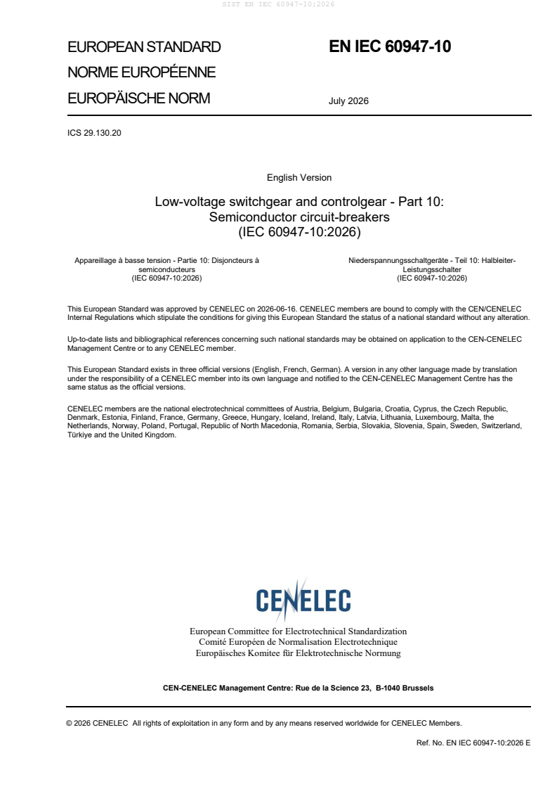
EUROPEAN STANDARD EN IEC 60947-10
NORME EUROPÉENNE
EUROPÄISCHE NORM July 2026
ICS 29.130.20
English Version
Low-voltage switchgear and controlgear - Part 10:
Semiconductor circuit-breakers
(IEC 60947-10:2026)
Appareillage à basse tension - Partie 10: Disjoncteurs à Niederspannungsschaltgeräte - Teil 10: Halbleiter-
semiconducteurs Leistungsschalter
(IEC 60947-10:2026) (IEC 60947-10:2026)
This European Standard was approved by CENELEC on 2026-06-16. CENELEC members are bound to comply with the CEN/CENELEC
Internal Regulations which stipulate the conditions for giving this European Standard the status of a national standard without any alteration.
Up-to-date lists and bibliographical references concerning such national standards may be obtained on application to the CEN-CENELEC
Management Centre or to any CENELEC member.
This European Standard exists in three official versions (English, French, German). A version in any other language made by translation
under the responsibility of a CENELEC member into its own language and notified to the CEN-CENELEC Management Centre has the
same status as the official versions.
CENELEC members are the national electrotechnical committees of Austria, Belgium, Bulgaria, Croatia, Cyprus, the Czech Republic,
Denmark, Estonia, Finland, France, Germany, Greece, Hungary, Iceland, Ireland, Italy, Latvia, Lithuania, Luxembourg, Malta, the
Netherlands, Norway, Poland, Portugal, Republic of North Macedonia, Romania, Serbia, Slovakia, Slovenia, Spain, Sweden, Switzerland,
Türkiye and the United Kingdom.
European Committee for Electrotechnical Standardization
Comité Européen de Normalisation Electrotechnique
Europäisches Komitee für Elektrotechnische Normung
CEN-CENELEC Management Centre: Rue de la Science 23, B-1040 Brussels
© 2026 CENELEC All rights of exploitation in any form and by any means reserved worldwide for CENELEC Members.
Ref. No. EN IEC 60947-10:2026 E
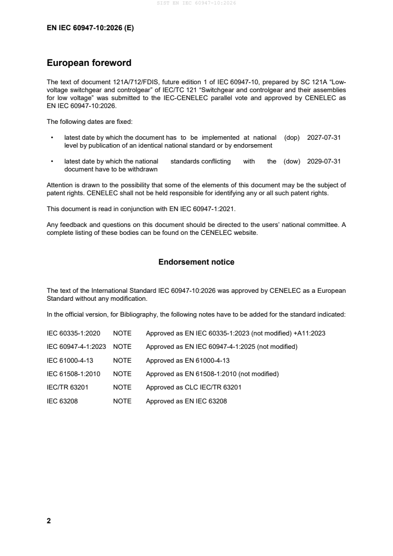
European foreword
The text of document 121A/712/FDIS, future edition 1 of IEC 60947-10, prepared by SC 121A “Low-
voltage switchgear and controlgear” of IEC/TC 121 “Switchgear and controlgear and their assemblies
for low voltage” was submitted to the IEC-CENELEC parallel vote and approved by CENELEC as
The following dates are fixed:
• latest date by which the document has to be implemented at national (dop) 2027-07-31
level by publication of an identical national standard or by endorsement
• latest date by which the national standards conflicting with the (dow) 2029-07-31
document have to be withdrawn
Attention is drawn to the possibility that some of the elements of this document may be the subject of
patent rights. CENELEC shall not be held responsible for identifying any or all such patent rights.
This document is read in conjunction with EN IEC 60947-1:2021.
Any feedback and questions on this document should be directed to the users’ national committee. A
complete listing of these bodies can be found on the CENELEC website.
Endorsement notice
The text of the International Standard IEC 60947-10:2026 was approved by CENELEC as a European
Standard without any modification.
In the official version, for Bibliography, the following notes have to be added for the standard indicated:
IEC 60335-1:2020 NOTE Approved as EN IEC 60335-1:2023 (not modified) +A11:2023
IEC 60947-4-1:2023 NOTE Approved as EN IEC 60947-4-1:2025 (not modified)
IEC 61000-4-13 NOTE Approved as EN 61000-4-13
IEC 61508-1:2010 NOTE Approved as EN 61508-1:2010 (not modified)
IEC/TR 63201 NOTE Approved as CLC IEC/TR 63201
IEC 63208 NOTE Approved as EN IEC 63208
Annex ZA
(normative)
Normative references to international publications
with their corresponding European publications
The following documents are referred to in the text in such a way that some or all of their content
constitutes requirements of this document. For dated references, only the edition cited applies. For
undated references, the latest edition of the referenced document (including any amendments)
applies.
NOTE 1 Where an International Publication has been modified by common modifications, indicated by (mod),
the relevant EN/HD applies.
NOTE 2 Up-to-date information on the latest versions of the European Standards listed in this annex is available
here: www.cencenelec.eu.
Publication Year Title EN/HD Year
IEC 60068-2-6 - Environmental testing - Part 2–6: Tests - EN 60068-2-6 -
Test Fc: Vibration (sinusoidal)
IEC 60068-2-14 - Environmental testing - Part 2–14: Tests - EN IEC 60068-2-14 -
Test N: Change of temperature
IEC 60068-2-30 - Environmental testing - Part 2–30: Tests - EN IEC 60068-2-30 -
Test Db: Damp heat, cyclic (12 h + 12 h
cycle)
IEC 60664-1 2020 Insulation coordination for equipment EN IEC 60664-1 2020
within low-voltage supply systems - Part 1:
Principles, requirements and tests
IEC 60695-2-11 2021 Fire hazard testing - Part 2–11: EN IEC 60695-2-11 2021
Glowing/hot-wire based test methods -
Glow-wire flammability test method for end
products (GWEPT)
IEC 60747-9 - Semiconductor devices - Part 9: Discrete - -
devices - Insulated-gate bipolar transistors
(IGBTs)
IEC 60749-5 - Semiconductor devices - Mechanical and EN IEC 60749-5 -
climatic test methods - Part 5: Steady-state
temperature humidity bias life test
IEC 60749-23 - Semiconductor devices - Mechanical and EN IEC 60749-23 -
climatic test methods - Part 23: High
temperature operating life
IEC 60749-25 - Semiconductor devices - Mechanical and EN 60749-25 -
climatic test methods - Part 25:
Temperature cycling
IEC 60749-34 - Semiconductor devices - Mechanical and EN 60749-34 -
climatic test methods - Part 34: Power
cycling
IEC 60947-1 2020 Low-voltage switchgear and controlgear - EN IEC 60947-1 2021
Part 1: General rules
IEC 60947-2 2024 Low-voltage switchgear and controlgear - EN IEC 60947-2 2025
Part 2: Circuit-breakers
IEC 61000-3-2 - Electromagnetic compatibility (EMC) - Part EN IEC 61000-3-2 -
3–2: Limits - Limits for harmonic current
emissions (equipment input current ≤ 16 A
per phase)
IEC 61000-3-3 - Electromagnetic compatibility (EMC) - Part EN 61000-3-3 -
3–3: Limits - Limitation of voltage changes,
voltage fluctuations and flicker in public
low-voltage supply systems, for equipment
with rated current ≤ 16 A per phase and
not subject to conditional connection
IEC 61000-4-2 2025 Electromagnetic compatibility (EMC) - Part EN IEC 61000-4-2 2025
4–2: Testing and measurement techniques
- Electrostatic discharge immunity test
IEC 61000-4-3 2020 Electromagnetic compatibility (EMC) - Part EN IEC 61000-4-3 2020
4–3: Testing and measurement techniques
- Radiated, radio-frequency,
electromagnetic field immunity test
IEC 61000-4-4 2012 Electromagnetic compatibility (EMC) - Part EN 61000-4-4 2012
4–4: Testing and measurement techniques
- Electrical fast transient/burst immunity
test
IEC 61000-4-5 2014 Electromagnetic compatibility (EMC) - Part EN 61000-4-5 2014
4–5: Testing and measurement techniques
- Surge immunity test
IEC 61000-4-6 2023 Electromagnetic compatibility (EMC) - Part EN IEC 61000-4-6 2023
4–6: Testing and measurement techniques
- Immunity to conducted disturbances,
induced by radio-frequency fields
IEC 61000-4-11 - Electromagnetic compatibility (EMC) - Part EN IEC 61000-4-11 -
4–11: Testing and measurement
techniques - Voltage dips, short
interruptions and voltage variations
immunity tests for equipment with input
current up to 16 A per phase
IEC 61000-4-29 - Electromagnetic compatibility (EMC) - Part EN 61000-4-29 -
4–29: Testing and measurement
techniques - Voltage dips, short
interruptions and voltage variations on d.c.
input power port immunity tests
IEC 61000-4-34 - Electromagnetic compatibility (EMC) - Part EN 61000-4-34 -
4–34: Testing and measurement
techniques - Voltage dips, short
interruptions and voltage variations
immunity tests for equipment with input
current more than 16 A per phase
IEC 61508-1 2010 Functional safety of EN 61508-1 2010
electrical/electronic/programmable
electronic safety-related systems - Part 1:
General requirements
IEC 61508-3 2010 Functional safety of EN 61508-3 2010
electrical/electronic/programmable
electronic safety-related systems - Part 3:
Software requirements
IEC 61709 - Electric components - Reliability - EN 61709 -
Reference conditions for failure rates and
stress models for conversion
IEC 62475 2010 High-current test techniques - Definitions EN 62475 2010
and requirements for test currents and
measuring systems
CISPR 11 2024 Industrial, scientific and medical equipment EN IEC 55011 2025
- Radio-frequency disturbance
characteristics - Limits and methods of
measurement
AEC-Q101 Failure mechanism based stress test
qualification for discrete semiconductors in
automotive applications
JEDEC JESD47 Stress-test-driven qualification of
integrated circuit
UL 991:2024 Tests for Safety-Related Controls
Employing Solid-State Devices
IEC 60947-10 ®
Edition 1.0 2026-05
INTERNATIONAL
STANDARD
Low-voltage switchgear and controlgear -
Part 10: Semiconductor circuit-breakers
ICS 29.130.20 ISBN 978-2-8327-1172-9
IEC 60947-10:2026-05(en)
IEC 60947-10:2026 © IEC 2026
CONTENTS
FOREWORD . 8
1 Scope . 10
2 Normative references . 10
3 Terms and definitions . 12
4 Classification . 15
4.1 According to type . 15
4.2 According to the operating mechanism method of the isolation contacts . 15
4.3 According to the position after tripping . 15
4.4 According to the method of controlling the operation . 16
4.5 According to the provision for software upgrade of embedded software . 16
4.6 According to the method of installation. 16
4.7 According to communication method . 16
4.8 According to the behaviour in case of loss of control circuit supply when the
circuit-breaker is in closed position . 16
4.9 According to the source of control circuit supply . 16
4.10 According to the degree of protection provided by the enclosure . 16
4.11 For DC circuit-breakers, according to the direction of current flow and
protection. 16
4.12 According to the existence of a standby state . 17
4.13 According to the integral cooling method of the breaker . 17
4.14 According to the surge withstand capability . 17
4.15 According to the single-pole voltage rating U for DC applications . 17
e1
5 Characteristics of circuit-breaker . 17
5.1 Summary of characteristics . 17
5.2 Type of circuit-breaker . 17
5.3 Rated and limiting values of the main circuit . 17
5.3.1 General . 17
5.3.2 Rated voltages . 18
5.3.3 Currents . 19
5.3.4 Rated frequency . 19
5.3.5 Rated duty . 19
5.3.6 Short-circuit characteristics . 19
5.3.7 Surge withstand capability . 21
5.3.8 Individual pole inductance . 24
5.4 Control circuits . 24
5.5 Auxiliary circuits . 24
5.6 Releases . 25
5.6.1 Release functions . 25
5.6.2 Characteristics . 25
5.6.3 Current setting of overcurrent releases . 26
5.6.4 Tripping time setting of overcurrent releases . 27
6 Product information . 27
6.1 Nature of the information . 27
6.2 Marking . 27
6.3 Instructions for installation, operation and maintenance instructions,
decommissioning and dismantling . 27
7 Normal service, mounting and transport conditions . 28
IEC 60947-10:2026 © IEC 2026
7.1 Normal service conditions . 28
7.1.1 Ambient air temperature . 28
7.1.2 Altitude . 28
7.1.3 Atmospheric conditions . 28
7.1.4 Shock and vibrations . 28
7.2 Conditions during transport and storage . 28
7.3 Mounting . 28
8 Constructional and performance requirements . 28
8.1 Constructional requirements . 28
8.1.1 General . 28
8.1.2 Withdrawable circuit-breakers . 29
8.1.3 Requirements for isolation function . 30
8.1.4 Clearances and creepage distances . 30
8.1.5 Requirements for the safety of the operator . 30
8.1.6 List of construction breaks . 30
8.1.7 Additional requirements for circuit-breakers provided with a neutral or
mid-point pole . 30
8.1.8 Digital inputs and outputs for use with programmable logic controllers
(PLCs) . 31
8.1.9 Indication of the closed position . 31
8.1.10 Indication of the standby position . 31
8.1.11 Indication of tripping . 31
8.1.12 Fault and abnormal conditions of electronic components . 31
8.1.13 Reliability of the breaking capability function . 31
8.2 Performance requirements . 31
8.2.1 Operating conditions . 31
8.2.2 Temperature rise . 33
8.2.3 Dielectric properties . 34
8.2.4 Ability to make and break under no load, normal load and overload
conditions . 34
8.2.5 Ability to make and break under short-circuit conditions . 35
8.2.6 Requirements for isolation function . 35
8.2.7 Requirements for behaviour in case of loss of control circuit supply . 35
8.3 Electromagnetic compatibility (EMC) . 36
9 Tests . 36
9.1 Kind of tests . 36
9.1.1 General . 36
9.1.2 Type tests. 36
9.1.3 Routine tests . 36
9.1.4 Special tests . 36
9.2 Compliance with constructional requirements . 36
9.2.1 General . 36
9.2.2 Breakdown of components . 36
9.2.3 Components tests . 37
9.3 Type tests . 38
9.3.1 General . 38
9.3.2 Test sequences . 38
9.3.3 General test conditions . 40
9.3.4 Test sequence I: General performance characteristics . 50
IEC 60947-10:2026 © IEC 2026
9.3.5 Test sequence II: Rated short-circuit breaking capacity . 63
9.3.6 Test sequence III: Rated individual pole ultimate short-circuit breaking
capacity at phase-to-neutral AC voltage . 64
9.3.7 Test sequence IV: Maximum admissible short-circuit current rate of rise. 66
9.3.8 Test sequence V: Additional verifications for circuit-breakers dependent
on line voltage (4.9 b)) or on an external voltage (4.9 c)) . 67
9.3.9 Test sequence VI: Rated individual pole ultimate short-circuit breaking
capacity at individual pole rated operational voltage U for DC circuit-
e1
breakers . 69
9.4 Routine tests . 70
9.4.1 General . 70
9.4.2 Mechanical operation tests . 70
9.4.3 Verification of the calibration of overcurrent releases . 70
9.4.4 Verification of the operation of undervoltage and shunt releases . 71
9.4.5 Dielectric tests . 71
9.4.6 Test for the verification of clearances less than those corresponding to
case A of IEC 60947-1:2020, Table 13 . 72
9.5 Special tests – Damp heat, salt mist, vibration and shock . 72
Annex A (normative) Coordination between a circuit-breaker and another short-circuit
protective device associated in the same circuit . 79
Annex B (normative) Circuit-breakers incorporating residual current protection . 80
Annex C (normative) Individual pole short-circuit test sequence for AC circuit-breakers . 81
C.1 General . 81
C.2 Test of individual pole short-circuit breaking capacity. 81
C.3 Verification of dielectric withstand, the leakage current and the standby
current . 81
C.4 Verification of overload releases . 81
Annex D (informative) Void . 82
Annex E (informative) Void . 83
Annex F (normative) Additional environmental tests . 84
F.1 General . 84
F.2 List of tests . 84
F.2.1 General . 84
F.2.2 Electromagnetic compatibility (EMC) tests . 84
F.2.3 Suitability for multiple frequencies . 86
F.2.4 Dry heat test . 86
F.2.5 Damp heat test . 86
F.2.6 Temperature variation cycles at a specified rate of change . 86
F.3 General test conditions . 86
F.3.1 General . 86
F.3.2 Conditions for immunity tests . 86
F.3.3 Conditions for emission tests . 87
F.4 Immunity tests . 87
F.4.1 Harmonic currents . 87
F.4.2 Electrostatic discharges . 89
F.4.3 Radiated RF electromagnetic fields . 89
F.4.4 Electrical fast transient/burst (EFT/B) . 89
F.4.5 Surges . 89
F.4.6 Conducted disturbances induced by RF fields (common mode) . 91
IEC 60947-10:2026 © IEC 2026
F.4.7 Current dips . 91
F.4.8 Voltage dips and interruptions . 92
F.5 Emission tests . 93
F.5.1 Harmonics . 93
F.5.2 Voltage fluctuations . 93
F.5.3 Conducted RF disturbances (150 kHz to 30 MHz) . 93
F.5.4 Radiated RF disturbances (30 MHz to 6 GHz). 93
F.6 Suitability for multiple frequencies. 93
F.6.1 General . 93
F.6.2 Test conditions . 93
F.6.3 Test procedure . 93
F.6.4 Test results . 94
F.7 Dry heat test . 94
F.7.1 Test procedure . 94
F.7.2 Test results . 94
F.7.3 Verification of overload releases . 94
F.8 Damp heat test . 94
F.8.1 Test procedure . 94
F.8.2 Verification of overload releases . 94
F.9 Temperature variation cycles at a specified rate of change . 95
F.9.1 Test conditions . 95
F.9.2 Temperature variation cycles without operational performance . 95
F.9.3 Temperature variation cycles with operational performance . 95
Annex G (normative) Power loss . 101
Annex H (normative) Test sequence for AC circuit-breakers suitable for IT systems . 102
H.1 General . 102
H.2 Individual pole short-circuit . 102
H.3 Verification of dielectric withstand, the leakage current and the standby
current . 103
H.4 Verification of overload releases . 103
H.5 Marking . 103
Annex I Void . 104
Annex J (normative) Electromagnetic compatibility (EMC) – Requirements and test
methods for circuit-breakers . 105
J.1 General . 105
J.2 Immunity . 105
J.2.1 General . 105
J.2.2 Electrostatic discharges . 107
J.2.3 Radiated RF electromagnetic fields . 107
J.2.4 Electrical fast transients/bursts (EFT/B) . 108
J.2.5 Surges . 108
J.2.6 Conducted disturbances induced by RF fields (common mode) . 108
J.3 Emission . 108
J.3.1 General . 108
J.3.2 Conducted RF disturbances (150 kHz to 30 MHz) . 109
J.3.3 Radiated RF disturbances (30 MHz to 6 000 MHz) . 109
Annex K (informative) Glossary of symbols and graphical representation of
characteristics . 110
IEC 60947-10:2026 © IEC 2026
Annex L (normative) Circuit-breakers not fulfilling the requirements for overcurrent
protection . 113
Annex M (normative) Modular residual current devices (without integral current
breaking device) . 114
Annex N (normative) Additional requirements for circuit-breakers preventing current
flow in one direction . 115
N.1 Scope and object . 115
N.2 Marking . 115
N.3 Performance requirements . 115
N.4 Tests . 115
Annex O (normative) Additional requirements for circuit breakers including a non-
switching or non-isolating pole . 116
O.1 Scope and object . 116
O.2 Circuit breakers with a non-switching pole . 116
O.2.1 Marking . 116
O.2.2 Performance requirements . 116
O.3 Circuit breakers with a non-isolating pole . 116
O.3.1 General aspects . 116
O.3.2 Marking . 116
O.3.3 Tests . 116
Annex P (normative) Reliability of the breaking capability function . 117
P.1 General . 117
P.2 Evaluation of firmware . 117
P.3 Critical component evaluation . 117
P.4 Breaking capability function . 118
P.5 Circuits to be addressed . 119
P.6 Self-test system . 119
P.7 Switching capability test in case of internal failure . 120
Bibliography . 121
Figure 1 – Test arrangement (connecting cables not shown) for short-circuit tests . 74
Figure 2 – Example of diagram for the temperature stabilization (see 9.3.3.7) of two-
pole DC circuit-breakers classified under 4.9 b) . 75
Figure 3 – Example of diagram for the temperature stabilization (see 9.3.3.7) of
three-pole AC circuit-breakers classified under 4.9 b) . 76
Figure 4 – Test circuit for the breaking operation of circuit breakers that cannot be
switched to the closed position without line power for the "O" operation . 77
Figure 5 – Examples for applying test and control circuit supply voltages for the
measurement of standby current for circuit-breakers classified under 4.9 b) . 78
Figure 6 – Example of a circuit-breaker tripping operation . 78
Figure 7 – Example of a reference curve, calibration curve and breaking curve . 78
Figure F.1 – Representation of test current produced by back-to-back thyristors in
accordance with F.4.1 . 96
Figure F.2 – Test circuit for immunity and emission tests for DC circuit-breakers . 97
Figure F.3 – Test circuit for immunity and emission tests for AC circuit-breakers –
Three-phase connection example . 97
Figure F.4 – Test current for the verification of the influence of the current dips and
interruptions in accordance with F.4.7.1 . 98
IEC 60947-10:2026 © IEC 2026
Figure F.5 – Test circuit for the verification of the influence of surges in the main circuit
(line-to-earth) in accordance with F.4.5 for DC circuit-breakers – Two-pole connection
example . 98
Figure F.6 – Test circuit for the verification of the influence of surges in the main circuit
(line-to-earth) in accordance with F.4.5 for AC circuit-breakers – Three-phase
connection example . 99
Figure F.7 – Test circuit for the verification of the influence of surges in the main circuit
(line-to-line) in accordance with F.4.5 for DC circuit-breakers – Two-pole connection
example . 99
Figure F.8 – Test circuit for the verification of the influence of surges in the main circuit
(line-to-line) in accordance with F.4.5 for AC circuit-breakers – Four-phase connection
example . 100
Figure F.9 – Temperature variation cycles at a specified rate of change in accordance
with F.9.2 . 100
Figure K.1 – Relationship between symbols and tripping characteristics . 112
Figure P.1 – Critical component investigation flowchart . 118
Table 1 – Ratio n between short-circuit making capacity and short-circuit breaking
capacity and related power factor (for AC circuit-breakers) (see 5.3.6.3) . 19
Table 2 – Product information . 22
Table 3 – Preferred values of the rated control circuit supply voltage, if different from
that of the main circuit . 24
Table 4 – Temperature-rise limits for terminals and accessible parts . 26
Table 5 – Characteristics of the opening operation of inverse time-delay overcurrent
opening releases . 26
Table 6 – Number of operating cycles . 35
Table 7 – Overall schema of test sequences . 39
Table 8 – Number of samples for test . 41
Table 9 – Values of power factors and circuit inductance corresponding to test currents . 45
Table 10 – Test sequences I . 50
Table 11 – Maximum standby current. 55
Table 12 – Test circuit characteristics for overload performance . 59
Table 13 – Test sequence II: Rated short-circuit breaking capacity . 63
Table 14 – Test sequence III: Rated individual pole ultimate short-circuit breaking
capacity at phase-to-neutral AC voltage . 65
Table 15 – Test sequence IV: Maximum admissible short-circuit current rate of rise . 66
Table 16 – Test sequence VI: Rated individual pole ultimate short-circuit breaking
capacity at individual pole rated operational voltage U for DC circuit-breakers . 69
e1
Table 17 – Principle for the application of the alternative test programs . 73
Table 18 – Applicability of tests or test sequences to 1, 2 and 4-pole circuit-breakers
according to the alternative program 1 . 73
Table 19 – Applicability of tests or test sequences to 1, 2 and 3-pole circuit-breakers
according to the alternative program 2 . 73
Table C.1 – Tests of Annex C . 81
Table F.1 – Test details for EMC tests . 84
Table F.2 – Performance criteria for immunity tests . 85
Table F.3 – Test parameters for current dips and interruptions . 91
Table F.4 – AC test criteria for voltage dips and interruptions . 92
IEC 60947-10:2026 © IEC 2026
Table F.5 – DC test criteria for voltage dips and interruptions . 92
Table H.1 – Tests of Annex H . 102
Table H.2 – Product information . 103
Table J.1 – EMC – Immunity tests . 106
Table J.2 – EMC – Emission tests . 109
Table K.1 – Symbols and graphical representation of characteristics . 110
IEC 60947-10:2026 © IEC 2026
INTERNATIONAL ELECTROTECHNICAL COMMISSION
____________
Low-voltage switchgear and controlgear -
Part 10: Semic
...