

prEN IEC 61851-23:2026
(Main)Conductive power and energy transfer systems for electric vehicles - Part 23: DC electric vehicle supply equipment
- Status
- Not Published
- Publication Date
- 23-Feb-2028
- Technical Committee
- CLC/TC 69X - Electrical systems for electric road vehicles
- Current Stage
- 4020 - Enquiry circulated - Enquiry
- Start Date
- 18-Sep-2026
- Due Date
- 30-Jun-2026
- Completion Date
- 18-Sep-2026

prEN IEC 61851-23:2026 is a CENELEC draft of IEC 61851-23 for conductive power and energy transfer systems for electric vehicles, focused on direct current (DC) electric vehicle supply equipment (EVSE). As a committee draft for vote, it is still under review. It sets the rules for how DC EVSE is classified, controlled, protected, built, tested, marked, and documented.
What does prEN IEC 61851-23:2026 specify?
prEN IEC 61851-23:2026 covers DC EVSE for conductive charging of electric vehicles. Clause 1 sets the scope, and Clauses 2 to 16 cover normative references, terms and definitions, general requirements, classification, charging modes and functions, communications, electric shock protection, conductive interface requirements, cable assemblies, constructional requirements and tests, overload and short-circuit protection, optional emergency switching, marking and instructions, specific requirements, and test methods.
The annexes give the system-specific rules and test procedures for different EVSE architectures. They are split by system so designers and test labs can apply the right circuit, sequence, and compliance checks for the equipment type they are working on.
| Annex | What it covers |
|---|---|
| Annex A | EVSE of system A, including circuit diagram, safety requirements, forward power transfer process, bidirectional power transfer (BPT), and compliance tests |
| Annex B | EVSE of upgraded system B, including compatibility with legacy EV and digital communication sequences |
| Annex C | EVSE of system C, including configurations EE and FF, energy transfer process, safety functions, additional functions, and test conditions |
| Annex D | EVSE of system D, including configuration GG, energy transfer process, safety functions, additional functions, compatibility requirements, and test conditions |
| Annex E | Behaviour and requirements at side B to support grid code compliance for system C |
What are the key requirements of prEN IEC 61851-23:2026?
Charging control and communication
prEN IEC 61851-23:2026 uses Clause 5 to classify EVSE by side A characteristics, environmental and mechanical conditions, mounting method, protection against electric shock, charging mode, separation type, control system, thermal management, power distribution, reverse power transfer, and operating voltage range. In practice, this means a buyer or engineer can identify which equipment family the draft applies to before comparing systems.
Clause 6 focuses on Charging Mode 4 and lists mandatory and optional functions. Clause 7 then defines the basic communication interface and digital communication between the EVSE and the EV. That matters because charging current, voltage, state changes, and shutdown decisions depend on communication, not only on power hardware.
Safety, protection, and shutdown behaviour
Clause 8 is the main safety section. It covers intended use and foreseeable misuse, touch current or touch voltage limits, basic protection, fault protection, enhanced protective provisions, and special requirements for separated EVSE. It also addresses equipotential bonding, protective conductor continuity, automatic disconnection of supply, residual current protective devices, insulation barriers, stored energy, and disconnection from the vehicle.
The practical effect is that the EVSE has to remain safe both in normal operation and under single-fault conditions. Designers and test labs need to prove that accessible parts stay within the required limits, that protective conductors and fault paths work, and that shutdown leaves the system in a safe state.
Clause 12 adds overload and short-circuit protection, including the DC connection during energy transfer and thermal effects during grid forming mode. Clause 13 makes emergency switching optional, but when used it becomes part of the safety concept. Clause 14 ties safety to information delivery by requiring installation and user manuals, marking, and durability of the marking.
Cables, construction, and validation testing
Clause 9 covers the conductive electrical interface, including neutral conductor wiring and avoiding breaking under load. Clause 10 sets requirements for cable assemblies, including dielectric withstand, dimensions, strain relief, storage or management means, cable breakaway sequence, and surface temperature of the side B cable assembly. These points matter because the cable is a frequent wear and abuse point in daily charging use.
Clause 11 covers the EVSE constructional requirements and tests. It includes clearances and creepage distances, ingress protection, insulation resistance, touch current, dielectric withstand voltage, temperature rise, damp heat, minimum temperature, power supply cords, abnormal operation and simulated fault tests, fire protection, chemical hazards, enclosures, components bridging insulation, isolating transformers, and corrosion resistance. Clause 16 then sets the test methods, general test conditions, measuring instruments, test setups, test loads, and operating points.
System-specific annexes and special functions
Annex A defines system A as a regulated EVSE using a dedicated CAN communication circuit, with a vehicle coupler of configuration AA. It states that the rated maximum voltage at side B is up to 1 000 V DC and says the system is suitable for passenger vehicles and light trucks. Annex A also includes optional BPT, with use cases such as vehicle-to-load (V2L), vehicle-to-home (V2H), and vehicle-to-grid (V2G).
Annex B defines upgraded system B and its compatibility with legacy EV using configuration BB. Annex C and Annex D define systems C and D, including their circuit diagrams, start-up and shutdown sequences, safety-related functions, compatibility checks, load dump, current regulation, and test cases. Annex E adds side B behaviour needed to support grid code compliance for system C, including disturbance immunity, active power response, interface protection, voltage support by reactive power, and event notification.
What terms does prEN IEC 61851-23:2026 define?
- Electric vehicle supply equipment (EVSE) - the charging equipment that connects the supply network to the electric vehicle and controls DC energy transfer.
- Electric vehicle (EV) - the vehicle that receives charging energy and exchanges control signals with the EVSE.
- Side A - the supply-network side of the EVSE, where the upstream electrical connection is made.
- Side B - the vehicle side of the EVSE, where DC charging output and related safety functions are controlled.
- Constant current mode (CCM) - a mode where the EVSE regulates side B current to a target current.
- Constant voltage mode (CVM) - a mode where the EVSE regulates side B voltage to a target voltage.
- Forward power transfer (FPT) - the normal transfer of energy from the EVSE to the EV.
- Bidirectional power transfer (BPT) - the optional reverse power transfer function used for cases such as V2L, V2H, and V2G.
Who uses prEN IEC 61851-23:2026?
This draft is used by EVSE manufacturers, vehicle manufacturers, charging system integrators, and test laboratories. It is also relevant to certification bodies, quality managers, installers, and buyers who need to compare DC charging equipment on technical, safety, and interoperability grounds.
In practice, they use it to design DC charging hardware, define communication behaviour, verify protection functions, build cable assemblies, prepare manuals and markings, and run compliance tests for system A, B, C, or D equipment.
What changed in prEN IEC 61851-23:2026 from the previous edition?
prEN IEC 61851-23:2026 is draft edition 3 and it supersedes documents 69/1076/CD and 69/1155/CC.
Which standards are used with prEN IEC 61851-23:2026?
| Standard | What it contributes |
|---|---|
| IEC 61851-24:2027 / IEC 61851-24:202X | Digital communication and communication actions/parameters for system A and system B annexes |
| IEC 62196-1 | Surface temperature requirements for the side B cable assembly |
| IEC 62196-3 and IEC TS 62196-3-1 | Vehicle coupler configurations and connector details used in the annexes and figures |
| IEC 60990:2016 | Measuring networks for touch current measurements |
| IEC 60479-1:2018 and IEC 60479-2:2019 | Human body current effects, perception and pain curves, and touch-current interpretation |
| IEC 61140:2016 | Protection against electric shock and related safety basis |
| IEC 62477-1:2022 | Reference basis for touch current and special protection values |
| ISO 5474-3:2024 | EV battery system reference points, Y-capacitance context, and voltage-related assumptions |
| ISO 15118 | High-level communication used in Annex C pause and renegotiation functions |
| IEC 61316:2025 | Cable reel storage check for overheating prevention |
| IEC 61439-7 | Guidance for extreme environment or special service conditions |
| IEC 60320-1 and the IEC 60364 series | Cord combinations and higher-current cord sizing references |
| ISO 7010-W017:2011-05 and ISO 7010-W001:2011-05 | Warning markings for hot surface or general warning on the cable assembly |
| ISO 19642-5:2019 | Cable types and thermal test arrangements used in thermal performance testing |
| IEEE Std 2030.1.1 | Additional information noted for system A |
What does the prEN IEC 61851-23:2026 document contain?
The draft contains circuit diagrams, sequence diagrams, tables of operating points, and annex-specific compliance tests. It also includes test arrangements for cable anchorage, thermal sensing, emergency shutdown, startup and shutdown sequences, and grid-code-related behaviour.
For testing and certification work, the most useful parts are the tables for conductor sizes, touch current, shutdown timing, pull force and torque, thermal parameters, and operating conditions. The figures show how to set up the EV simulator, test load, connector anchorage, and the different system-specific control sequences.
Relations
- Effective Date
- 20-May-2025
Get Certified
Connect with accredited certification bodies for this standard

TÜV Rheinland
TÜV Rheinland is a leading international provider of technical services.

TÜV SÜD
TÜV SÜD is a trusted partner of choice for safety, security and sustainability solutions.

DEKRA Certification Inc.
DEKRA US certification services.
Sponsored listings
Frequently Asked Questions
prEN IEC 61851-23:2026 is a draft published by CLC. Its full title is "Conductive power and energy transfer systems for electric vehicles - Part 23: DC electric vehicle supply equipment". This standard covers: Conductive power and energy transfer systems for electric vehicles - Part 23: DC electric vehicle supply equipment
Conductive power and energy transfer systems for electric vehicles - Part 23: DC electric vehicle supply equipment
prEN IEC 61851-23:2026 is classified under the following ICS (International Classification for Standards) categories: 43.120 - Electric road vehicles. The ICS classification helps identify the subject area and facilitates finding related standards.
prEN IEC 61851-23:2026 has the following relationships with other standards: It is inter standard links to EN IEC 61851-23:2026/A11:2026. Understanding these relationships helps ensure you are using the most current and applicable version of the standard.
prEN IEC 61851-23:2026 is associated with the following European legislation: EU Directives/Regulations: 2014/35/EU; Standardization Mandates: M/468, M/511, M/581. When a standard is cited in the Official Journal of the European Union, products manufactured in conformity with it benefit from a presumption of conformity with the essential requirements of the corresponding EU directive or regulation.
prEN IEC 61851-23:2026 is available in PDF format for immediate download after purchase. The document can be added to your cart and obtained through the secure checkout process. Digital delivery ensures instant access to the complete standard document.
Standards Content (Sample)
SLOVENSKI STANDARD
01-november-2026
Sistemi za prenos prevodne moči in energije za električna vozila - 23. del: Postaja
za kabelsko napajanje električnega vozila z enosmernim tokom
Conductive power and energy transfer systems for electric vehicles - Part 23: DC electric
vehicle supply equipment
Konduktive Ladesysteme für Elektrofahrzeuge - Teil 23:
Gleichstromversorgungseinrichtungen für Elektrofahrzeuge
Système de charge par conduction pour véhicules électriques - Partie 23: Système
d'alimentation en courant continu pour véhicules électriques
Ta slovenski standard je istoveten z: prEN IEC 61851-23:2026
ICS:
43.120 Električna cestna vozila Electric road vehicles
2003-01.Slovenski inštitut za standardizacijo. Razmnoževanje celote ali delov tega standarda ni dovoljeno.
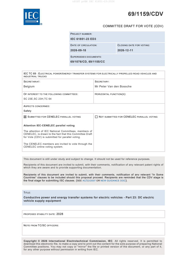
69/1159/CDV
COMMITTEE DRAFT FOR VOTE (CDV)
PROJECT NUMBER:
IEC 61851-23 ED3
DATE OF CIRCULATION: CLOSING DATE FOR VOTING:
2026-09-18 2026-12-11
SUPERSEDES DOCUMENTS:
69/1076/CD, 69/1155/CC
IEC TC 69 : ELECTRICAL POWER/ENERGY TRANSFER SYSTEMS FOR ELECTRICALLY PROPELLED ROAD VEHICLES AND
INDUSTRIAL TRUCKS
SECRETARIAT: SECRETARY:
Belgium Mr Peter Van den Bossche
OF INTEREST TO THE FOLLOWING COMMITTEES: HORIZONTAL FUNCTION(S):
SC 23E,SC 23H,TC 64
ASPECTS CONCERNED:
Safety
SUBMITTED FOR CENELEC PARALLEL VOTING NOT SUBMITTED FOR CENELEC PARALLEL VOTING
Attention IEC-CENELEC parallel voting
The attention of IEC National Committees, members of
CENELEC, is drawn to the fact that this Committee Draft
for Vote (CDV) is submitted for parallel voting.
The CENELEC members are invited to vote through the
CENELEC online voting system.
This document is still under study and subject to change. It should not be used for reference purposes.
Recipients of this document are invited to submit, with their comments, notification of any relevant patent rights of
which they are aware and to provide supporting documentation.
Recipients of this document are invited to submit, with their comments, notification of any relevant “In Some
Countries” clauses to be included should this proposal proceed. Recipients are reminded that the CDV stage is
the final stage for submitting ISC clauses. (SEE AC/22/2007 OR NEW GUIDANCE DOC).
TITLE:
Conductive power and energy transfer systems for electric vehicles - Part 23: DC electric
vehicle supply equipment
PROPOSED STABILITY DATE: 2028
NOTE FROM TC/SC OFFICERS:
download this electronic file, to make a copy and to print out the content for the sole purpose of preparing National
Committee positions. You may not copy or "mirror" the file or printed version of the document, or any part of it,
for any other purpose without permission in writing from IEC.
IEC CDV 61851-23 © IEC 2026
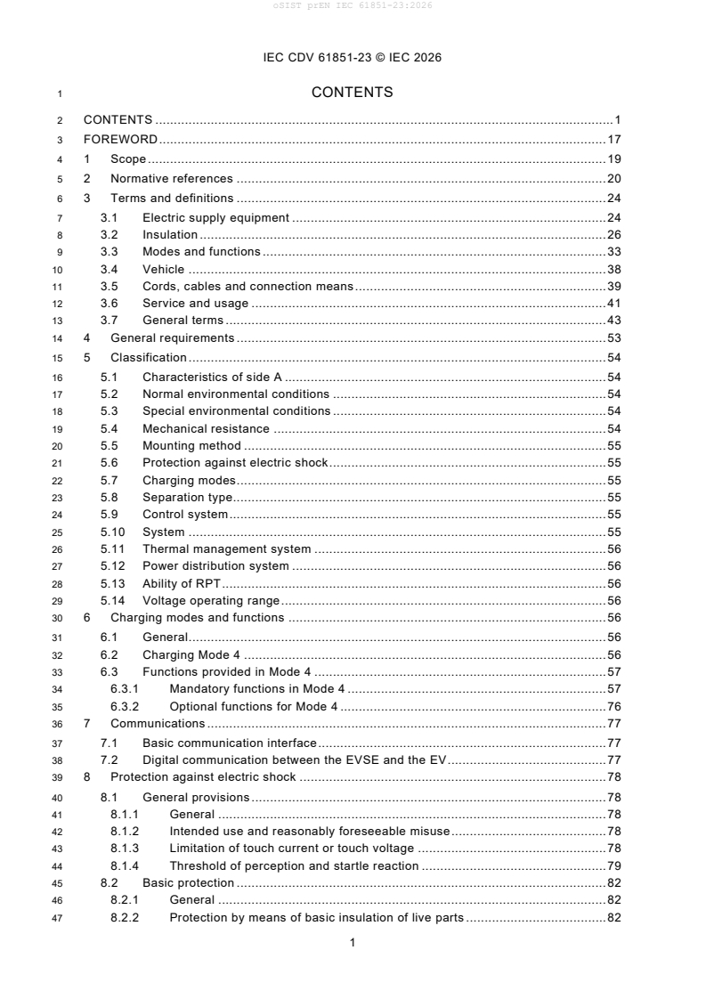
1 CONTENTS
2 CONTENTS . 1
3 FOREWORD . 17
4 1 Scope . 19
5 2 Normative references . 20
6 3 Terms and definitions . 24
7 3.1 Electric supply equipment . 24
8 3.2 Insulation . 26
9 3.3 Modes and functions . 33
10 3.4 Vehicle . 38
11 3.5 Cords, cables and connection means . 39
12 3.6 Service and usage . 41
13 3.7 General terms . 43
14 4 General requirements . 53
15 5 Classification . 54
16 5.1 Characteristics of side A . 54
17 5.2 Normal environmental conditions . 54
18 5.3 Special environmental conditions . 54
19 5.4 Mechanical resistance . 54
20 5.5 Mounting method . 55
21 5.6 Protection against electric shock . 55
22 5.7 Charging modes . 55
23 5.8 Separation type. 55
24 5.9 Control system . 55
25 5.10 System . 55
26 5.11 Thermal management system . 56
27 5.12 Power distribution system . 56
28 5.13 Ability of RPT . 56
29 5.14 Voltage operating range . 56
30 6 Charging modes and functions . 56
31 6.1 General . 56
32 6.2 Charging Mode 4 . 56
33 6.3 Functions provided in Mode 4 . 57
34 6.3.1 Mandatory functions in Mode 4 . 57
35 6.3.2 Optional functions for Mode 4 . 76
36 7 Communications . 77
37 7.1 Basic communication interface . 77
38 7.2 Digital communication between the EVSE and the EV . 77
39 8 Protection against electric shock . 78
40 8.1 General provisions . 78
41 8.1.1 General . 78
42 8.1.2 Intended use and reasonably foreseeable misuse . 78
43 8.1.3 Limitation of touch current or touch voltage . 78
44 8.1.4 Threshold of perception and startle reaction . 79
45 8.2 Basic protection . 82
46 8.2.1 General . 82
47 8.2.2 Protection by means of basic insulation of live parts . 82
IEC CDV 61851-23 © IEC 2026
48 8.2.3 Protection by means of enclosures or barriers . 82
49 8.2.4 Protection by means of limitation of voltage . 82
50 8.2.5 Protection by means of limitation of steady-state touch current . 84
51 8.3 Fault protection . 84
52 8.3.1 General . 84
53 8.3.2 Protective-equipotential-bonding . 84
54 8.3.3 Effective protective conductor continuity between the enclosure and the
55 external protective circuit . 84
56 8.3.4 Automatic disconnection of supply . 85
57 8.3.5 Supplementary insulation . 85
58 8.3.6 Electrically protective screening. 85
59 8.3.7 Fault protection in grid forming mode . 85
60 8.4 Enhanced protective provision . 85
61 8.4.1 General . 85
62 8.4.2 Double or reinforced insulation . 85
63 8.4.3 Protective separation between circuits . 85
64 8.5 Requirements for separated EVSE . 86
65 8.5.1 General . 86
66 8.5.2 Equipotential bonding on side B . 88
67 8.5.3 Impedance to protective conductor on side B . 88
68 8.5.4 Degrees of protection against access to hazardous-live-parts . 89
69 8.5.5 Insulation barriers . 90
70 8.5.6 Stored energy . 92
71 8.5.7 Disconnection from vehicle . 92
72 8.5.8 Protective (earthing) conductor from the supply network . 92
73 8.5.9 Residual current protective devices . 93
74 8.5.10 Safety requirements for auxiliary circuits between the EVSE and the EV . 94
75 8.5.11 Protective conductor dimension cross-sectional area . 94
76 9 Conductive electrical interface requirements . 94
77 9.1 General . 94
78 9.7 Wiring of the neutral conductor . 94
79 9.8 Avoidance of breaking under load . 94
80 10 Cable assembly requirements . 95
81 10.1 General . 95
82 10.2 Dielectric withstand characteristics . 95
83 10.3 Cable dimensions . 95
84 10.4 Strain relief . 95
85 10.4.1 General . 95
86 10.4.2 Strain relief of the side B cable assembly of the EVSE . 95
87 10.4.3 Test of the anchorage of the side B cable assembly . 96
88 10.5 Cable management and storage means for cables assemblies . 98
89 10.6 Cable breakaway . 98
90 10.7 Surface temperature of the side B cable assembly . 99
91 11 EVSE constructional requirements and tests . 99
92 11.1 General . 99
93 11.2 Characteristics of mechanical switching devices . 99
94 11.2.1 General . 99
95 11.2.2 Circuit-breaker . 99
96 11.3 Clearances and creepage distances . 100
IEC CDV 61851-23 © IEC 2026
97 11.4 IP degrees . 100
98 11.4.1 Degrees of protection against solid foreign objects and water for the
99 enclosures . 100
100 11.4.2 Degrees of protection against solid foreign objects and water for vehicle
101 connectors . 101
102 11.5 Insulation resistance . 101
103 11.6 Touch current . 101
104 11.6.1 Touch current limit . 101
105 11.6.2 Test . 102
106 11.6.3 Protection measures for the test touch current more than 3,5 mA . 102
107 11.7 Dielectric withstand voltage . 103
108 11.7.1 AC or DC withstand voltage . 103
109 11.7.2 Impulse dielectric withstand (1,2 μs/50 μs) . 104
110 11.7.3 Suppression of transient overvoltage at side A (insulation coordination) . 104
111 11.7.4 Protection against transient overvoltages of atmospheric origin or due
112 to switching . 104
113 11.8 Temperature rise . 108
114 11.9 Damp heat functional test . 108
115 11.10 Minimum temperature functional test . 108
116 11.11 Side A current . 108
117 11.12 Power supply cords . 108
118 11.12.1 General . 108
119 11.12.2 Cross-sectional area . 109
120 11.12.3 Cord anchorages and strain relief for non-detachable power supply
121 cords . 110
122 11.13 Stress relief test . 111
123 11.14 Abnormal operation and simulated fault condition tests . 112
124 11.14.1 General . 112
125 11.14.2 Pass criteria . 112
126 11.14.3 Breakdown of components test . 113
127 11.14.4 Loss of AC supply phase test. 113
128 11.14.5 Inoperative blower/fan motor test . 113
129 11.14.6 Clogged filter test . 114
130 11.15 Protection against electrically caused fire . 114
131 11.15.1 General . 114
132 11.15.2 Fire enclosure. 114
133 11.16 Protection against chemical hazards . 114
134 11.16.1 Type of coolant . 114
135 11.16.2 Flammability . 115
136 11.16.3 Material compatibility . 115
137 11.17 Enclosures . 115
138 11.17.1 General . 115
139 11.17.2 Strength of materials and parts . 115
140 11.17.3 Enclosure integrity tests . 116
141 11.18 Components bridging insulation . 116
142 11.18.1 General . 116
143 11.18.2 Capacitors . 116
144 11.19 Isolating transformers . 116
145 11.20 Protection against corrosion . 117
146 11.20.1 General . 117
IEC CDV 61851-23 © IEC 2026
147 11.20.2 Protection against corrosion test . 118
148 12 Overload and short-circuit protection . 119
149 12.1 General . 119
150 12.2 Short-circuit protection of the DC connection during energy transfer . 119
151 12.3 Protection against thermal effect due to short circuit during grid forming
152 mode . 121
153 13 Emergency switching (optional) . 121
154 14 Marking and instructions . 121
155 14.1 Installation manual of EV charging stations . 121
156 14.2 User manual for EVSE . 123
157 14.3 Marking of EVSE . 123
158 14.4 Durability test for marking . 124
159 15 Specific requirements for EVSE . 124
160 15.1 Specific requirements for separated EVSE . 124
161 15.1.1 Operating ranges for voltage, current, and power at side B . 124
162 15.1.2 Voltage and current tolerance at side B . 125
163 15.1.3 Control delay of present current at side B in CCM. 127
164 15.1.4 Descending rate of present current at side B . 131
165 15.1.5 Periodic and random deviation (current ripple at side B during CCM) . 131
166 15.1.6 Periodic and random deviation (voltage ripple at side B during CVM) . 132
167 15.1.7 Load dump . 133
168 15.1.8 Side B inductance . 134
169 15.1.9 Limitation of dynamic behaviour during normal operation . 136
170 15.2 Specific requirement for energy transfer with a thermal management system
171 or thermal sensing only . 137
172 15.2.1 General . 137
173 15.2.2 Temperature limits and self-diagnostics . 137
174 15.2.3 Temperature monitoring . 138
175 15.2.4 Tests for thermal management system performance of the EVSE . 139
176 15.3 Specific requirements for temperature-controlled energy transfer with rated
177 boost current. 149
178 16 Test methods . 150
179 16.1 Technical data . 150
180 16.2 General test conditions . 150
181 16.2.1 Ambient test conditions . 150
182 16.2.2 Measuring instruments. 151
183 16.2.3 Test setups . 151
184 16.2.4 Test load . 156
185 16.2.5 Operating points for tests . 157
186 Annex A (normative) EVSE of system A . 159
187 A.1 General . 159
188 A.2 Circuit diagram . 159
189 A.3 Specific safety requirements . 162
190 A.3.1 Fault protection in side B . 162
191 A.3.2 De-energization of the power supply to the EV . 166
192 A.3.3 Voltage measurement of side B live parts (DC+/DC–) for vehicle
193 connector unlatch . 166
194 A.3.4 Overcurrent protection of side B . 167
195 A.3.5 Short-circuit protection of side B . 167
IEC CDV 61851-23 © IEC 2026
196 A.3.6 Latch monitoring for the vehicle connector . 168
197 A.3.7 Protection of the EV disconnection device . 169
198 A.3.8 Fault conditions and criteria for transfer to error and emergency
199 shutdown . 169
200 A.3.9 Inrush current limitation by the EVSE. 174
201 A.3.10 Regulation of the present current at side B in CCM . 174
202 A.3.11 Periodic and random deviation (current ripple at side B during CCM) . 175
203 A.3.12 Overvoltage protection including load dump . 176
204 A.3.13 Power supply to the EV for the actuation of EV disconnection device . 177
205 A.3.14 Impedance of the side B circuit . 178
206 A.3.15 Assistance of welding detection . 178
207 A.3.16 Specific requirements for temperature-controlled energy transfer . 178
208 A.4 FPT process and communication between the EVSE and the EV for energy
209 transfer control . 179
210 A.4.1 Forward power transfer states . 179
211 A.4.2 Communication measures . 181
212 A.4.3 Forward power transfer control process . 181
213 A.4.4 Measuring current and voltage at side B . 188
214 A.5 Response to an EV command on charge current . 190
215 A.6 Bidirectional power transfer (optional) . 192
216 A.6.1 General . 192
217 A.6.2 Circuit diagram . 192
218 A.6.3 Functional requirements . 194
219 A.6.4 Bidirectional power transfer control process . 196
220 A.7 Optional functions . 201
221 A.7.1 General . 201
222 A.7.2 Compatibility check . 201
223 A.7.3 Dynamic control . 201
224 A.7.4 High-current control . 202
225 A.7.5 High-voltage control . 202
226 A.8 Compliance test for user-initiated shutdown . 202
227 A.9 Specific requirement for energy transfer with thermal management system . 202
228 Annex B (normative) EVSE of upgraded system B . 204
229 B.1 General . 204
230 B.2 Circuit diagrams . 204
231 B.2.1 Circuit diagram . 204
232 B.2.2 Requirements of IMD and discharge circuit . 206
233 B.2.3 Requirements of auxiliary power supply circuit. 206
234 B.3 Parameters of control pilot circuit . 206
235 B.4 Process of FPT . 208
236 B.4.1 General . 208
237 B.4.2 Normal startup . 208
238 B.4.3 Normal shutdown and error shutdown . 210
239 B.4.4 Emergency shutdown. 212
240 B.4.5 Backward compatibility (optional) . 216
241 B.5 Energy transfer requirements . 219
242 B.5.1 Side B regulation . 219
243 B.5.2 Measuring current and voltage . 219
244 B.5.3 Vehicle coupler mating confirmation . 221
IEC CDV 61851-23 © IEC 2026
245 B.5.4 Insulation resistance check before energy transfer . 221
246 B.5.5 Normal shutdown . 222
247 B.5.6 Error handling . 223
248 B.5.7 Emergency handling . 225
249 B.6 Specific requirements . 226
250 B.6.1 Electronic lock and latch monitoring for vehicle connector . 226
251 B.6.2 Manual emergency unlocking mechanism . 227
252 B.6.3 Insulation monitoring function at power supply mode . 227
253 B.6.4 Welding detection . 228
254 B.6.5 Load dump . 228
255 B.6.6 Overcurrent protection of side B . 229
256 B.6.7 Short-circuit protection of side B . 229
257 B.6.8 Overvoltage fault . 230
258 B.6.9 Power failure protection . 230
259 B.6.10 Minimum cross-sectional area of the protective conductor . 231
260 B.6.11 Side B current regulation in CCM . 231
261 B.6.12 Side B voltage regulation in CVM . 233
262 B.6.13 Periodic and random deviation (voltage ripple at side B in CVM) . 235
263 B.6.14 Energy transfer control mode . 235
264 B.7 Additional functions . 237
265 B.7.1 Pause function . 237
266 B.7.2 Automatic restore communication . 238
267 B.7.3 Restart and sleep mode . 238
268 Annex C (normative) EVSE of system C . 239
269 C.1 General . 239
270 C.2 Circuit diagrams . 239
271 C.2.1 General . 239
272 C.2.2 Circuit diagram for configuration EE . 239
273 C.2.3 Circuit diagram for configuration FF . 242
274 C.2.4 Control pilot function requirements . 245
275 C.2.5 Disabled side B . 245
276 C.3 Process of energy transfer . 246
277 C.3.1 General . 246
278 C.3.2 Normal startup . 248
279 C.3.3 Normal shutdown or pause after energy transfer . 258
280 C.3.4 Error and emergency handling . 263
281 C.3.5 Pause by EVSE using ISO 15118 . 276
282 C.3.6 Renegotiation initiated by EV or EVSE. 291
283 C.3.7 Additional parameters in HLC . 295
284 C.4 Safety related functions . 296
285 C.4.1 Safety measures for side B . 296
286 C.4.2 Vehicle coupler latching function . 300
287 C.4.3 Loss of electrical continuity of the control pilot conductor . 300
288 C.4.4 Loss of electrical continuity of the proximity detection conductor . 300
289 C.4.5 Minimum cross-sectional area of the protective conductor . 300
290 C.4.6 Loss of electrical continuity of the protective conductor . 300
291 C.5 Additional functions . 300
292 C.5.1 Pre-charge . 300
293 C.5.2 Sleep mode and communication session restart methods . 303
IEC CDV 61851-23 © IEC 2026
294 C.5.3 Configuration EE vehicle connector latch position switch (S 3)
S
295 activation . 309
296 C.5.4 Configuration EE vehicle connector latch position switch (S 3)
S
297 verification . 309
298 C.5.5 Handling of operating ranges . 310
299 C.5.6 Compatibility check . 319
300 C.5.7 Considerations for CCM, CVM and CPM (informative) . 331
301 C.6 Specific requirements . 332
302 C.6.1 Requirements for load dump . 332
303 C.6.2 Side B current regulation . 332
304 C.6.3 Measuring current and voltage at side B . 333
305 C.6.4 Overcurrent protection of side B . 333
306 C.7 General test conditions . 333
307 C.7.1 Operating points – Definitions . 333
308 C.7.2 Standard test setup . 335
309 C.7.3 Definition of measured values at side B . 335
310 C.7.4 Exemplary approach to set a test point in CCM . 335
311 C.7.5 Test cases . 338
312 Annex D (normative) EVSE of system D . 396
313 D.1 General . 396
314 D.2 Circuit diagrams . 396
315 D.2.1 General . 396
316 D.2.2 Circuit diagram for configuration GG . 396
317 D.2.3 Disabled side B . 405
318 D.3 Process of energy transfer . 407
319 D.3.1 General . 407
320 D.3.2 Normal startup . 408
321 D.3.3 Normal shutdown during energy transfer . 415
322 D.3.4 Error and emergency handling . 418
323 D.3.5 Pause by EVSE . 428
324 D.4 Safety related functions . 428
325 D.4.1 Safety measures for side B . 428
326 D.4.2 Vehicle coupler latching function . 432
327 D.4.3 Loss of electrical continuity of the control pilot conductor . 432
328 D.4.4 Loss of electrical continuity of the proximity detection conductor . 432
329 D.4.5 Voltage check at initialization. 432
330 D.4.6 Minimum cross-sectional area of the protective conductor . 432
331 D.4.7 Loss of electrical continuity of the protective conductor . 433
332 D.5 Additional functions . 433
333 D.5.1 Pre-charge . 433
334 D.5.2 Handling of operating ranges . 433
335 D.5.3 Compatibility check (Parameter configuration) . 433
336 D.6 Specific requirements . 433
337 D.6.1 Requirements for load dump . 433
338 D.6.2 Side B current regulation . 434
339 D.6.3 Measuring current and voltage at side B . 434
340 D.6.4 Overcurrent protection of side B . 434
341 D.6.5 AC/DC overlay . 435
342 D.7 Compatibility requirements . 435
IEC CDV 61851-23 © IEC 2026
343 D.8 General test conditions . 435
344 D.8.1 Operating points – Definitions . 436
345 D.8.2 Standard test setup . 437
346 D.8.3 Definition of measured values at side B . 437
347 D.8.4 Exemplary approach to set a test point in CCM . 437
348 D.8.5 Test cases . 439
349 Annex E (normative) Behaviour and requirements at side B to support grid code
350 compliance for system C.
...