

EN IEC 60851-5:2026
(Main)Winding wires - Test methods - Part 5: Electrical properties
- Status
- Not Published
- Publication Date
- 08-Oct-2026
- Technical Committee
- CLC/TC 55 - Winding wires
- Current Stage
- 6055 - Ratification Completed (DOR) - Publishing
- Start Date
- 17-Sep-2026
- Completion Date
- 17-Sep-2026

EN IEC 60851-5:2026 is the European standard for test methods for the electrical properties of winding wires, published by CLC in line with IEC 60851-5. It specifies how to measure electrical resistance, breakdown voltage, continuity of insulation, dielectric dissipation factor and pin hole performance for winding wires used in electrical equipment.
What does EN IEC 60851-5:2026 specify?
EN IEC 60851-5:2026 specifies the electrical test methods used for winding wires. Clause 1 lists the five tests covered, and Clause 2 points users to IEC 60851-1 for definitions and general notes on the test series.
The document is organized as follows:
- Clause 3 - Test 5: Electrical resistance
- Clause 4 - Test 13: Breakdown voltage
- Clause 5 - Test 14: Continuity of insulation
- Clause 6 - Test 19: Dielectric dissipation factor
- Clause 7 - Test 23: Pin hole test
- Annex A - informative methods for dissipation factor measurement and interpretation
| Annex | What it covers |
|---|---|
| Annex A | Dissipation factor methods, including tangent delta examples and ways to interpret the results |
In practice, this part tells laboratories and manufacturers how to prepare specimens, which test setups to use, and what to report for each electrical property.
What are the key requirements of EN IEC 60851-5:2026?
EN IEC 60851-5:2026 sets out a small group of electrical tests, but each one has a specific setup and reporting rule. The key point for users is that the method changes with wire construction, diameter and, in some cases, temperature.
Electrical resistance
Clause 3 defines electrical resistance as the d.c. resistance at 20 °C of 1 m of wire. The method must give a precision of 0.5 %, and when resistance is measured at another temperature, the result is corrected to 20 °C using the stated temperature coefficient.
For bunched wires, the standard uses a longer specimen, up to 10 m, with soldered ends before measurement. This matters because the result is used both for normal resistance checks and for checking whether too many wires are broken in a bunch.
Breakdown voltage
Clause 4 specifies breakdown voltage testing with an a.c. test voltage of 50 Hz or 60 Hz that starts at zero and rises at a uniform rate. Table 1 gives the rise rates, so the test voltage does not increase arbitrarily.
The clause also defines the equipment: a test transformer, fault detection, a controlled voltage-rise arrangement, an oven, and the specimen holders or containers needed for each wire type. This matters because the test result depends on the test field, the contact arrangement and the way the specimen is supported.
Specimen preparation depends on wire construction and size. For enamelled round wire, the standard uses a cylinder method or a twisted specimen method, while larger round wire, fibre wound round wire and rectangular wire use mandrel and shot-bath arrangements. Table 4 summarizes which preparation method applies, so users can select the correct setup instead of adapting one method to all wires.
At room temperature, five specimens are tested and the five individual values are reported. At elevated temperature, the specimen and test medium are preheated, the voltage is applied after at least 15 minutes in the oven, and the test must be completed within 30 minutes while keeping temperature within the stated tolerance.
Continuity of insulation
Clause 5 measures continuity of insulation as the number of faults per length of wire detected by an electrical circuit. The clause separates low-voltage continuity from high-voltage continuity, because very fine wire needs a gentler setup than thicker wire.
For low-voltage continuity, the wire passes between felt pads in sodium sulphate solution under a 50 V d.c. open-circuit test voltage. The result is the number of faults per 30 m. This is useful for process control on fine enamelled wire, where the user wants a direct fault count on a fixed length.
For high-voltage continuity, the standard uses either off-line testing or in-line testing. The wire is pulled over a V-grooved electrode or through a graphite brush electrode, and the d.c. test voltage is selected from Tables 4.1, 4.2 or 5 according to wire type, diameter and grade. The practical effect is that the test voltage is matched to the wire category, so the fault count reflects the intended product class.
Clause 5.4 also covers in-line high-voltage continuity during enamelling, just before take-up on a drum, spool or reel. The result records both run length and fault count, which makes the method suitable for production monitoring rather than only sample testing.
Dielectric dissipation factor
Clause 6 treats the wire as a capacitor and measures the dielectric dissipation factor from the capacitive and resistive components of the circuit. The test uses an impedance meter, a frequency generator and one of two specimen methods: a metal bath electrode or a conductive suspension electrode.
The result must report the dielectric dissipation factor, test frequency and test temperature. That matters because the value depends on both temperature and frequency, so the report needs all three to be meaningful.
Annex A gives example methods for tangent delta measurement and explains how to interpret the curve. It is informative, but it is useful when a user needs to assess curing behaviour of the enamel rather than just obtain a single pass/fail reading.
Pin hole test
Clause 7 checks for insulation defects after treatment in a salt water solution. The specimen is heat treated first, then immersed in an electrolytic solution with phenolphthalein and tested at low d.c. voltage for one minute.
The result is the number of visible pin holes, counted without magnification. In practice, this is a defect-detection test for insulation quality, and the heat treatment is part of the method because the standard states that results are not significant without it.
What terms does EN IEC 60851-5:2026 define?
EN IEC 60851-5:2026 uses a few terms that are central to its test methods.
- Electrical resistance - The d.c. resistance at 20 °C of 1 m of wire, used to check conductor performance.
- Breakdown voltage - The a.c. test voltage applied to determine when insulation fails under the specified rise rate and specimen setup.
- Continuity of insulation - The number of insulation faults detected per length of wire by an electrical test circuit.
- HVC - High-voltage continuity, the fault-counting test used off-line or in-line for enamelled wire and related wire grades.
- Dielectric dissipation factor - The measured loss factor of the insulated wire acting as a capacitor, used as an indicator of enamel behaviour.
- Pin hole test - A defect test that reveals insulation flaws after heat treatment and immersion in electrolyte.
Who uses EN IEC 60851-5:2026?
EN IEC 60851-5:2026 is used by winding wire manufacturers, test laboratories, and quality teams that need to verify electrical properties of insulated wire. It is also used by buyers and engineering teams who specify acceptance testing for wire intended for motors, transformers and other electrical equipment.
In practice, users apply it for type testing, routine quality checks, process monitoring during enamelling, and investigation of insulation defects or breakdown behaviour.
What changed in EN IEC 60851-5:2026 from the previous edition?
EN IEC 60851-5:2026 states two significant revisions compared with the previous edition:
- Clause 4.3.2 was modified to expand the conductor size range for the loads used in cylinder-method breakdown voltage testing of enamelled wires and fully insulated wires.
- Clause 5.5 was added for inline continuity testing of rectangular wire, and it is noted as under consideration.
Which standards are used with EN IEC 60851-5:2026?
EN IEC 60851-5:2026 depends on IEC 60851-1 for definitions, general notes on test methods and the full series of winding-wire test methods. The introduction also places this part in the wider family of winding-wire standards alongside IEC 60317 for specifications for particular types of winding wires and IEC 60264 for packaging of winding wires.
What does the EN IEC 60851-5:2026 document contain?
EN IEC 60851-5:2026 contains the procedures, specimen preparations, apparatus requirements and reporting rules for five electrical tests. It also includes several figures for specimen arrangements and electrode layouts, and tables that set voltage rise rates, loads, twist counts, cylinder sizes and test voltages.
The body of the document is heavily procedural, so it is aimed at laboratories and production teams that need repeatable setups rather than general guidance. Annex A adds worked examples and interpretation methods for dissipation factor measurements, which is useful when comparing curing behaviour across samples or methods.
Relations
- Effective Date
- 04-Jul-2023
- Effective Date
- 04-Jul-2023
- Effective Date
- 04-Jul-2023
Get Certified
Connect with accredited certification bodies for this standard

IMQ S.p.A. (Certification)
Italian electrical product certification.

SLG Prüf- und Zertifizierungs GmbH
German testing and certification body.

UL Solutions
Global safety science company with testing, inspection and certification.
Sponsored listings
Frequently Asked Questions
EN IEC 60851-5:2026 is a draft published by CLC. Its full title is "Winding wires - Test methods - Part 5: Electrical properties". This standard covers: Winding wires - Test methods - Part 5: Electrical properties
Winding wires - Test methods - Part 5: Electrical properties
EN IEC 60851-5:2026 is classified under the following ICS (International Classification for Standards) categories: 29.060.10 - Wires. The ICS classification helps identify the subject area and facilitates finding related standards.
EN IEC 60851-5:2026 has the following relationships with other standards: It is inter standard links to EN 60851-5:2008, EN 60851-5:2008/A1:2011, EN 60851-5:2008/A2:2019. Understanding these relationships helps ensure you are using the most current and applicable version of the standard.
EN IEC 60851-5:2026 is available in PDF format for immediate download after purchase. The document can be added to your cart and obtained through the secure checkout process. Digital delivery ensures instant access to the complete standard document.
Standards Content (Sample)
SLOVENSKI STANDARD
oSIST prEN IEC 60851-5:2025
01-julij-2025
Navijalne žice - Preskusne metode - 5. del: Električne lastnosti
Winding wires - Test methods - Part 5: Electrical properties
Wickeldrähte - Prüfverfahren - Teil 5: Elektrische Eigenschaften
Fils de bobinage - Méthodes d'essai - Partie 5: Propriétés électriques
Ta slovenski standard je istoveten z: prEN IEC 60851-5:2025
ICS:
29.060.10 Žice Wires
oSIST prEN IEC 60851-5:2025 en
2003-01.Slovenski inštitut za standardizacijo. Razmnoževanje celote ali delov tega standarda ni dovoljeno.
oSIST prEN IEC 60851-5:2025
oSIST prEN IEC 60851-5:2025
55/2066/CDV
COMMITTEE DRAFT FOR VOTE (CDV)
PROJECT NUMBER:
IEC 60851-5 ED5
DATE OF CIRCULATION: CLOSING DATE FOR VOTING:
2025-06-13 2025-09-05
SUPERSEDES DOCUMENTS:
55/2061/CD, 55/2064/CC
IEC TC 55 : WINDING WIRES
SECRETARIAT: SECRETARY:
United States of America Mr Mike Leibowitz
OF INTEREST TO THE FOLLOWING COMMITTEES: HORIZONTAL FUNCTION(S):
TC 2,TC 14
ASPECTS CONCERNED:
Safety
SUBMITTED FOR CENELEC PARALLEL VOTING NOT SUBMITTED FOR CENELEC PARALLEL VOTING
Attention IEC-CENELEC parallel voting
The attention of IEC National Committees, members of
CENELEC, is drawn to the fact that this Committee Draft
for Vote (CDV) is submitted for parallel voting.
The CENELEC members are invited to vote through the
CENELEC online voting system.
This document is still under study and subject to change. It should not be used for reference purposes.
Recipients of this document are invited to submit, with their comments, notification of any relevant patent rights of
which they are aware and to provide supporting documentation.
Recipients of this document are invited to submit, with their comments, notification of any relevant “In Some
Countries” clauses to be included should this proposal proceed. Recipients are reminded that the CDV stage is
the final stage for submitting ISC clauses. (SEE AC/22/2007 OR NEW GUIDANCE DOC).
TITLE:
Winding wires - Test methods - Part 5: Electrical properties
PROPOSED STABILITY DATE: 2027
NOTE FROM TC/SC OFFICERS:
electronic file, to make a copy and to print out the content for the sole purpose of preparing National Committee positions.
You may not copy or "mirror" the file or printed version of the document, or any part of it, for any other purpose without
permission in writing from IEC.
oSIST prEN IEC 60851-5:2025
IEC CDV 60851-5 © IEC 2025 – 3 – 55/2066/CDV
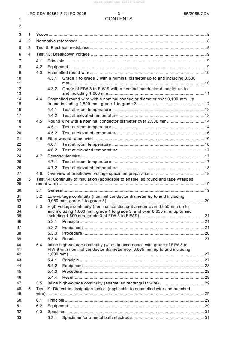
1 CONTENTS
3 1 Scope . 8
4 2 Normative references . 8
5 3 Test 5: Electrical resistance. 8
6 4 Test 13: Breakdown voltage . 9
7 4.1 Principle . 9
8 4.2 Equipment . 9
9 4.3 Enamelled round wire . 10
10 4.3.1 Grade 1 to grade 3 with a nominal diameter up to and including 0,500
11 mm . 10
12 4.3.2 Grade of FIW 3 to FIW 9 with a nominal conductor diameter up to
13 and including 1,600 mm . 11
14 4.4 Enamelled round wire with a nominal conductor diameter over 0,100 mm up
15 to and including 2,500 mm, grade 1 to grade 3 . 12
16 4.4.1 Test at room temperature . 12
17 4.4.2 Test at elevated temperature . 13
18 4.5 Round wire with a nominal conductor diameter over 2,500 mm . 14
19 4.5.1 Test at room temperature . 14
20 4.5.2 Test at elevated temperature . 16
21 4.6 Fibre wound round wire . 16
22 4.6.1 Test at room temperature . 16
23 4.6.2 Test at elevated temperature . 17
24 4.7 Rectangular wire . 17
25 4.7.1 Test at room temperature . 17
26 4.7.2 Test at elevated temperature . 18
27 4.8 Overview of breakdown voltage specimen preparation. 18
28 5 Test 14: Continuity of insulation (applicable to enamelled round and tape wrapped
29 round wire) . 19
30 5.1 General . 19
31 5.2 Low-voltage continuity (nominal conductor diameter up to and including
32 0,050 mm, grade 1 to grade 3) . 20
33 5.3 High-voltage continuity (nominal conductor diameter over 0,050 mm up to
34 and including 1,600 mm, grade 1 to grade 3, and over 0,035 mm, up to and
35 including 1,600 mm, grade 3 of FIW 3 to FIW 9) . 21
36 5.3.1 Principle . 21
37 5.3.2 Equipment . 21
38 5.3.3 Procedure . 26
39 5.3.4 Result . 27
40 5.4 Inline high-voltage continuity (wires in accordance with grade of FIW 3 to
41 FIW 9 with nominal conductor diameter over 0,035 mm up to and including
42 1,600 mm) . 27
43 5.4.1 Principle . 27
44 5.4.2 Equipment . 28
45 5.4.3 Procedure . 28
46 5.4.4 Result . 29
47 5.5 Inline high-voltage continuity (enamelled rectangular wire) . 29
48 6 Test 19: Dielectric dissipation factor (applicable to enamelled wire and bunched
49 wire) . 29
50 6.1 Principle . 29
51 6.2 Equipment . 29
52 6.3 Specimen . 31
53 6.3.1 Specimen for a metal bath electrode . 31
oSIST prEN IEC 60851-5:2025
IEC CDV 60851-5 © IEC 2025 – 4 – 55/2066/CDV
54 6.3.2 Specimen for a conductive suspension electrode . 31
55 6.4 Procedure . 31
56 6.5 Result . 31
57 7 Test 23: Pin hole test. 31
58 Annex A (informative) Dissipation factor methods . 33
59 A.1 Tangent delta – Intersection point . 33
60 A.2 Test methods . 33
61 A.2.1 Method A . 33
62 A.2.2 Method B – Wire coated with a conductive film . 34
63 A.3 Interpretation of results . 34
64 A.3.1 General . 34
65 A.3.2 Linear method . 34
66 A.3.3 Logarithmic method . 35
68 Figure 1 – Arrangement of cylinder and specimen for the breakdown voltage test . 11
69 Figure 2 – Device for twisting the specimen for breakdown voltage test . 13
70 Figure 3 – U-bend specimen for the breakdown voltage test (specimen placed in shot
71 bath) . 15
72 Figure 4 – Coil-wound specimen for the breakdown voltage test . 17
73 Figure 5 – Apparatus for testing the low-voltage continuity of covering . 20
74 Figure 6 – High-voltage d.c. continuity – Pulleys for wire size 0,050 mm to 0,250 mm . 23
75 Figure 7 – Pulley dimensions and spacing for wire size 0,250 mm to 1,600 mm . 23
76 Figure 8a – Graphite fibre single brush electrode assembly . 24
77 Figure 8b – Graphite fibre dual brush electrode assembly . 25
78 Figure 8 – Graphite fibre single or dual brush electrode asssembly . 25
79 Figure 9 – Suitable electrode arrangement for testing the dielectric dissipation factor . 30
80 Figure A.1 – Example of linear method for sole coating . 35
81 Figure A.2 – Example of logarithmic method for sole coating . 35
83 Table 1 – Rates of test voltage increase . 9
84 Table 2.1 – Loads applied to enamelled wire . 10
85 Table 2.2 – Loads and diameters of test cylinders applied to wire . 12
86 Table 3 – Loads applied to the wire and number of twists . 13
87 Table 4.1 – Off-line HVC test voltages for grades 1 – 3 . 26
88 Table 4.2 – Off-line HVC test voltages for grade of FIW 3 – FIW 9 . 27
89 Table 5 – In-line HVC test voltages . 29
oSIST prEN IEC 60851-5:2025
IEC CDV 60851-5 © IEC 2025 – 5 – 55/2066/CDV
93 INTERNATIONAL ELECTROTECHNICAL COMMISSION
94 ____________
96 WINDING WIRES –
97 TEST METHODS –
99 Part 5: Electrical properties
103 FOREWORD
104 1) The International Electrotechnical Commission (IEC) is a worldwide organization for standardization comprising
105 all national electrotechnical committees (IEC National Committees). The object of IEC is to promote international
106 co-operation on all questions concerning standardization in the electrical and electronic fields. To this end and
107 in addition to other activities, IEC publishes International Standards, Technical Specifications, Technical Reports,
108 Publicly Available Specifications (PAS) and Guides (hereafter referred to as “IEC Publication(s)”). Their
109 preparation is entrusted to technical committees; any IEC National Committee interested in the subject dealt with
110 may participate in this preparatory work. International, governmental and non-governmental organizations liaising
111 with the IEC also participate in this preparation. IEC collaborates closely with the International Organization for
112 Standardization (ISO) in accordance with conditions determined by agreement between the two organizations.
113 2) The formal decisions or agreements of IEC on technical matters express, as nearly as possible, an international
114 consensus of opinion on the relevant subjects since each technical committee has representation from all
115 interested IEC National Committees.
116 3) IEC Publications have the form of recommendations for international use and are accepted by IEC National
117 Committees in that sense. While all reasonable efforts are made to ensure that the technical content of IEC
118 Publications is accurate, IEC cannot be held responsible for the way in which they are used or for any
119 misinterpretation by any end user.
120 4) In order to promote international uniformity, IEC National Committees undertake to apply IEC Publications
121 transparently to the maximum extent possible in their national and regional publications. Any divergence between
122 any IEC Publication and the corresponding national or regional publication shall be clearly indicated in the latter.
123 5) IEC itself does not provide any attestation of conformity. Independent certification bodies provide conformity
124 assessment services and, in some areas, access to IEC marks of conformity. IEC is not responsible for any
125 services carried out by independent certification bodies.
126 6) All users should ensure that they have the latest edition of this publication.
127 7) No liability shall attach to IEC or its directors, employees, servants or agents including individual experts and
128 members of its technical committees and IEC National Committees for any personal injury, property damage or
129 other damage of any nature whatsoever, whether direct or indirect, or for costs (including legal fees) and
130 expenses arising out of the publication, use of, or reliance upon, this IEC Publication or any other IEC Publications.
131 8) Attention is drawn to the Normative references cited in this publication. Use of the referenced publications is
132 indispensable for the correct application of this publication.
133 9) Attention is drawn to the possibility that some of the elements of this IEC Publication may be the subject of patent
134 rights. IEC shall not be held responsible for identifying any or all such patent rights.
136 International Standard IEC 60851-5 has been prepared by IEC technical committee 55: Winding
137 wires.
138 Significant revisions to the previous edition include the following points:
139 • Subclause 4.3.2 modified to expand the conductor size range for the loads applied during
140 cylinder method testing for dielectric breakdown voltage of enameled wires and for fully
141 insulated wires.
142 • Addition of subclause 5.5 for inline continuity testing of rectangular wire (under
143 consideration).
146 This publication has been drafted in accordance with the ISO/IEC Directives, Part 2.
147 A list of all the parts in the IEC 60851 series, under the general title Winding wires − Test
148 methods, can be found on the website.
oSIST prEN IEC 60851-5:2025
IEC CDV 60851-5 © IEC 2025 – 6 – 55/2066/CDV
149 The committee has decided that the contents of the base publication and its amendments will
150 remain unchanged until the stability date indicated on the IEC web site under
151 "http://webstore.iec.ch" in the data related to the specific publication. At this date, the
152 publication will be
153 • reconfirmed,
154 • withdrawn,
155 • replaced by a revised edition, or
156 • amended.
oSIST prEN IEC 60851-5:2025
IEC CDV 60851-5 © IEC 2025 – 7 – 55/2066/CDV
160 INTRODUCTION
162 This part of IEC 60851 forms an element of a series of standards which deals with insulated
163 wires used for windings in electrical equipment. The series has three groups describing
164 a) winding wires – Test methods (IEC 60851);
165 b) specifications for particular types of winding wires (IEC 60317);
166 c) packaging of winding wires (IEC 60264).
oSIST prEN IEC 60851-5:2025
IEC CDV 60851-5 © IEC 2025 – 8 – 55/2066/CDV
169 WINDING WIRES –
170 TEST METHODS –
172 Part 5: Electrical properties
176 1 Scope
177 This part of IEC 60851 specifies the following tests:
178 – Test 5: Electrical resistance;
179 – Test 13: Breakdown voltage;
180 – Test 14: Continuity of insulation;
181 – Test 19: Dielectric dissipation factor;
182 – Test 23: Pin hole.
183 For definitions, general notes on methods of test and the complete series of methods of test for
184 winding wires, see IEC 60851-1.
185 2 Normative references
186 The following referenced documents are indispensable for the application of this document. For
187 dated references, only the edition cited applies. For undated references, the latest edition of
188 the referenced document (including any amendments) applies.
189 IEC 60851-1, Winding wires – Test methods – Part 1: General
190 3 Test 5: Electrical resistance
191 Electrical resistance is the d.c. resistance at 20 °C of 1 m of wire.
192 The method used shall provide a precision of 0,5 %.
193 For bunched wires a length of up to 10 m shall be used and the ends shall be soldered before
194 the measurement. When measuring the resistance to check for an excessive number of broken
195 wires, a length of 10 m of bunched wire shall be used.
196 If the resistance R is measured at a temperature t other than 20 °C, the resistance R at 20 °C
t 20
197 shall be calculated by means of the following formula:
R
t
198 R =
1+ (t − 20)
199 where
200 t is the actual temperature in degrees Celsius during the measurement;
–1
201 is the temperature coefficient in K .
oSIST prEN IEC 60851-5:2025
IEC CDV 60851-5 © IEC 2025 – 9 – 55/2066/CDV
203 In the temperature range from 15 °C to 25 °C, the temperature coefficient to be used shall be:
–3 –1
204 – for copper: = 3,96 10 K ;
–3 –1
205 – for aluminium: = 4,07 10 K .
206 One test shall be made. The electrical resistance shall be reported.
207 4 Test 13: Breakdown voltage
208 4.1 Principle
209 The test voltage shall be an a.c. voltage of 50 Hz or 60 Hz nominal frequency. The test voltage
210 shall be applied at zero and increased at a uniform rate according to Table 1.
211 Table 1 – Rates of test voltage increase
Breakdown voltage
Rate of
V
increase
Up to and
V/s
Over
including
– 500 20
500 2 500 100
2 500 – 500
213 An overview of breakdown voltage specimen preparations specified in 4.3 – 4.7 is provided in
214 4.8.
215 4.2 Equipment
216 The following equipment shall be used:
217 – test transformer with a rated power of at least 500 VA providing an a.c. voltage of an
218 undistorted sine waveform under test conditions, with a peak factor being within the limits
219 of 2 5 % (1,34 to 1,48) and with a capacity to supply a current of 5 mA with a maximum
220 voltage drop of 2 %;
221 – fault detection circuit, which operates at a current of 5 mA or more;
222 – arrangement to provide a uniform rise of the test voltage at the specified rate;
223 – oven with forced air circulation;
224 – polished metal cylinder, 25 mm 1 mm in diameter, mounted with its axis horizontal
225 (see Figure 1) and electrically connected to one terminal of the test voltage supply;
226 – twisting device according to Figure 2, that allows to twist two pieces of wire for a length of
227 125 mm;
228 – strips of metal foil, 6 mm in width and pressure sensitive tape, 12 mm in width;
229 – container with metal shot of stainless steel or nickel-plated iron. The diameter of the shot
230 shall not exceed 2 mm. The shot shall be cleaned periodically by suitable means;
231 – metal mandrel, 50 mm 2 mm in diameter;
232 – metal mandrel, 25 mm 1 mm in diameter;
233 – metal mandrel, 80 mm 3 mm in diameter.
oSIST prEN IEC 60851-5:2025
IEC CDV 60851-5 © IEC 2025 – 10 – 55/2066/CDV
235 4.3 Enamelled round wire
236 4.3.1 Grade 1 to grade 3 with a nominal diameter up to and including 0,500 mm
237 The test is carried out on a cylinder with a diameter of 25 mm 1 mm. A straight piece of wire
238 with the insulation removed at one end shall be connected to the upper terminal as shown in
239 Figure 1 and wound once around the cylinder. A load as specified in Table 2.1 shall be applied
240 to the lower end of the wire to keep the specimen in close contact with the cylinder.
241 The test voltage shall be applied according to 4.1 between the conductor of the wire and the
242 cylinder. The test shall be carried out at room temperature.
243 Five specimens shall be tested. The five single values shall be reported.
244 Table 2.1 – Loads applied to enamelled wire
Nominal conductor diameter
Load
mm
Up to and
Over
including N
–
0,018 0,013
0,018
0,020 0,015
0,020
0,022 0,020
0,022
0,025 0,025
0,025
0,028 0,030
0,028
0,032 0,040
0,032
0,036 0,050
0,036
0,040 0,060
0,040
0,045 0,080
0,045
0,050 0,100
0,050
0,056 0,120
0,056
0,063 0,150
0,063
0,071 0,200
0,071
0,080 0,250
0,080
0,090 0,300
0,090
0,100 0,400
0,100
0,160 0,600
0,160
0,250 0,850
0,250
0,355 1,700
0,355
0,500 3,400
oSIST prEN IEC 60851-5:2025
IEC CDV 60851-5 © IEC 2025 – 11 – 55/2066/CDV
Test voltage Test voltage
Load
IEC 1271/08
249 1 specimen
250 2 insulating material
251 3 upper terminal
252 4 cylinder
253 Figure 1 – Arrangement of cylinder and specimen
254 for the breakdown voltage test
255 4.3.2 Grade of FIW 3 to FIW 9 with a nominal conductor diameter up to
256 and including 1,600 mm
257 The test is carried out on a cylinder with a diameter as set out in Table 2.2.
258 A straight piece of wire with the insulation removed at one end shall be connected to the upper
259 terminal as shown in Figure 1 and wound once around the cylinder. A load as specified in Table
260 2.2 shall be applied to the lower end of the wire to keep the specimen in close contact with the
261 cylinder.
262 The test voltage shall be applied according to 4.1 between the conductor of the wire and the
263 cylinder. The test shall be carried out at room temperature. Five specimens shall be tested. The
264 five single values shall be reported.
oSIST prEN IEC 60851-5:2025
IEC CDV 60851-5 © IEC 2025 – 12 – 55/2066/CDV
266 Table 2.2 – Loads and diameters of test cylinders applied to wire
Nominal diameter Nominal diameter Load Diameter of test cylinder
mm mm N mm
Over Up to and including
- 0,040 0,080 25 1
0,040 0,045 0,100 25 1
0,045 0,050 0,130 25 1
0,050 0,056 0,160 25 1
0,056 0,063 0,200 25 1
0,063 0,071 0,260 25 1
0,071 0,080 0,330 25 1
0,080 0,090 0,400 25 1
0,090 0,100 0,500 25 1
0,100 0,160 0,600 25 1
0,160 0,250 0,850 25 1
0,250 0,355 1,700 25 1
0,355 0,500 3,400 25 1
0,500 0,710 7,000 50 2
0,710 1,060 13,500 50 2
1,060 1,400 27,000 80 3
1,400 1,600 54,000 80 3
268 4.4 Enamelled round wire with a nominal conductor diameter over 0,100 mm
269 up to and including 2,500 mm, grade 1 to grade 3
270 4.4.1 Test at room temperature
271 A straight piece of wire, approximately 400 mm in length, with the insulation removed at both
272 ends, shall be twisted back on itself for a distance of (125 5) mm on the twisting device as
273 shown in Figure 2. The ends of the wire shall be joined, and the load applied with the number
274 of twists, as given in Table 3. The loop at the end of the twisted section shall be cut at two
275 places to provide a maximum spacing between the cut ends. Any bending to ensure adequate
276 separation between the two wire ends shall avoid sharp bends or damage to the coating.
277 The test voltage shall be applied according to 4.1 between the conductors of the wires.
278 Five specimens shall be tested. The five single values shall be reported.
oSIST prEN IEC 60851-5:2025
IEC CDV 60851-5 © IEC 2025 – 13 – 55/2066/CDV
280 Table 3 – Loads applied to the wire and number of twists
Nominal conductor diameter
Load
mm Number
of twists
Up to and
N
Over
including
0,100 0,250 0,85 33
0,250 0,355 1,70 23
0,355 0,500 3,40 16
0,500 0,710 7,00 12
0,710 1,060 13,50 8
1,060 1,400 27,00 6
1,400 2,000 54,00 4
2,000 2,500 108,00 3
Load
1 3 2
IEC 1272/08
283 1 spacer
284 2 rotary hook
285 3 specimen
286 Figure 2 – Device for twisting the specimen for breakdown voltage test
287 4.4.2 Test at elevated temperature
288 A specimen prepared according to 4.4.1 shall be placed in the oven preheated to the specified
289 test temperature 3 °C. The test voltage shall be applied according to 4.1 between the
290 conductors of the wires in not less than 15 min after placing the specimen in the oven. The test
291 shall be completed within 30 min.
292 Five specimens shall be tested. The five single values shall be reported.
oSIST prEN IEC 60851-5:2025
IEC CDV 60851-5 © IEC 2025 – 14 – 55/2066/CDV
294 4.5 Round wire with a nominal conductor diameter over 2,500 mm
295 4.5.1 Test at room temperature
296 A straight piece of wire of sufficient length, with the insulation removed at one end, shall be
297 bent around a mandrel as shown in Figure 3.
298 The diameter of the mandrel shall be 50 mm 2 mm.
299 The specimen shall be placed in the container and shall be surrounded by shot at least 5 mm
300 between the specimen and the inner walls of the container. The ends of the specimen shall be
301 sufficiently long to avoid flashover.
302 The shot shall be poured gently into a container until the specimen is covered by shot at a depth
303 of 90 mm. The metal shot shall be not more than 2 mm in diameter; balls of stainless steel,
304 nickel or nickel-plated iron have been found suitable. The shot shall be cleaned periodically
305 with a suitable solvent (for example, 1,1,1-trichloroethane).
306 The test voltage shall be applied according to 4.1, between the conductor and the shot.
307 NOTE By agreement between the purchaser and the supplier, the test may be carried out with the specimen under
308 oil. Oil should be in accordance with IEC 60296 or as agreed upon between customer and supplier.
309 Five specimens shall be tested. The five single values shall be reported.
oSIST prEN IEC 60851-5:2025
IEC CDV 60851-5 © IEC 2025 – 15 – 55/2066/CDV
311 Dimensions in millimetres
Test voltage electrodes
Bent wire specimen
~
Filling of metal shot not
more than 2 mm
diameter
5 5
25
or
50
IEC 1273/08
313 Figure 3 – U-bend specimen for the breakdown voltage test
314 (specimen placed in shot bath)
5 90
oSIST prEN IEC 60851-5:2025
IEC CDV 60851-5 © IEC 2025 – 16 – 55/2066/CDV
316 4.5.2 Test at elevated temperature
317 A specimen prepared according to 4.5.1 shall be placed in the oven preheated to the specified
318 test temperature 3 °C. The shot and container shall be preheated within the oven at the test
319 temperature and kept there during the loading of the test specimen. The loading operation of
320 the test specimen shall be performed very gently in order to avoid damage to the specimen.
321 The test voltage shall be applied according to 4.1 between the conductor and the shot in not
322 less than 15 min after placing the specimen in the oven. The test shall be completed within
323 30 min.
324 The temperature shall be kept within 3 °C.
325 Five specimens shall be tested. The five single values shall be reported.
326 4.6 Fibre wound round wire
327 4.6.1 Test at room temperature
328 A straight piece of wire of sufficient length with the insulation removed at one end shall be bent
329 10 turns around a mandrel as shown in Figure 4. The diameter of the mandrel shall be
330 – 25 mm 1 mm for nominal diameter up to and including 2,500 mm;
331 – 50 mm 2 mm for nominal diameter over 2,500 mm.
332 The specimen shall be placed in the container as shown in Figure 4 and shall be surrounded
333 by shot at least 5 mm between the specimen and the inner walls of the container. There shall
334 be a minimum distance of 2,5 mm between adjacent turns. The ends of the specimen shall be
335 sufficiently long to avoid flashover.
336 The shot shall be poured gently into the container until the specimen is covered by shot at a
337 depth of 90 mm. The metal shot shall not be more than 2 mm in diameter; balls of stainless
338 steel, nickel or nickel-plated iron have been found suitable. The shot shall be cleaned once per
339 year.
340 The test voltage shall be applied according to 4.1 between the conductor of the wire and the
341 shot.
342 NOTE By agreement between the purchaser and the supplier, the test may be carried out with the specimen under
343 oil. Oil should be in accordance with IEC 60296 or as agreed upon between customer and supplier.
344 Five specimens shall be
...