

IEC TS 62607-6-24:2026
(Main)Nanomanufacturing - Key control characteristics - Part 6-24: Graphene-related products - Number of layers of graphene: optical contrast
- Abstract
IEC TS 62607-6-24:2026 which is a Technical Specification, establishes a standardized method to determine the key control characteristic (KCC)
• number of layer distribution
for CVD graphene film by
• optical contrast measurement
The number of layers and number of layer distribution of CVD graphene film is derived by G‑channel contrast values.
This method is applicable for clean CVD graphene film without twisted multilayer structures on a SiO2/Si substrate.
- Status
- Published
- Publication Date
- 28-Jun-2026
- Technical Committee
- TC 113 - Nanotechnology for electrotechnical products and systems
- Drafting Committee
- WG 8 - TC 113/WG 8
- Current Stage
- PPUB - Publication issued
- Start Date
- 29-Jun-2026
- Completion Date
- 17-Jul-2026
Buy Documents
IEC TS 62607-6-24:2026 - Nanomanufacturing - Key control characteristics - Part 6-24: Graphene-related products - Number of layers of graphene: optical contrast
IEC TS 62607-6-24:2026 is an IEC Technical Specification for nanomanufacturing of graphene-related products. It specifies a standardized optical-contrast method to determine the number of layer distribution in CVD graphene film by using G-channel contrast values on a SiO2/Si substrate. The document is meant for people who need a repeatable way to quantify how much of a graphene film is monolayer, bilayer, or multilayer.
What does IEC TS 62607-6-24:2026 specify?
IEC TS 62607-6-24:2026 specifies a method for measuring the key control characteristic (KCC) called number of layer distribution for CVD graphene film. The method uses optical contrast measurement and derives both the number of layers and the layer distribution from G-channel contrast values.
The scope is limited to clean CVD graphene film without twisted multilayer structures on a SiO2/Si substrate. In practice, that means the procedure is for optical inspection of transferred films on the stated substrate structure, not for every graphene sample type.
The document is organized into seven clauses and four annexes:
| Annex | What it covers |
|---|---|
| Annex A | Optical contrast values for samples with known number of layers |
| Annex B | How to acquire the number of layer distribution of monolayer CVD graphene |
| Annex C | How to acquire the number of layer distribution of CVD graphene with multilayer domains |
| Annex D | Transfer of CVD grown graphene films |
Clause 1 gives the scope, Clause 2 lists the normative reference, Clause 3 defines terms, Clause 4 explains the principle and equipment, Clause 5 gives the measurement procedure, Clause 6 covers data analysis, and Clause 7 states what to report.
What are the key requirements of IEC TS 62607-6-24:2026?
IEC TS 62607-6-24:2026 requires a controlled optical workflow: prepare the sample on the correct substrate, calibrate the camera, capture sample and blank images under the same conditions, convert them into G-channel contrast images, and then use contrast peaks to assign layer numbers and coverage ratios.
1. Use the stated substrate and sample condition
Clause 4.3 says the substrate should be Si with a (300 ± 5) nm SiO2 layer, and the method applies to clean CVD graphene film without twisted multilayer structures. This matters because the contrast values depend on the substrate stack and on whether the film is suitable for the optical model.
2. Establish a layer-to-contrast correlation before analyzing target films
Clause 5.1 requires standard graphene samples with known layer numbers, with the layer count identified by Raman spectroscopy, to build the correlation between G-channel contrast value and number of layers. In practice, this calibration step turns the optical method into a usable layer assignment tool for later measurements.
3. Calibrate the imaging system consistently
Clause 5.2 requires white balance calibration using a standard whiteboard with reflectance of at least 99 %. Clause 5.3 then requires capturing a blank substrate image and adjusting brightness so the grey value is between 125 and 135. This reduces camera and lighting bias, which is important because the method compares pixel values across images.
4. Capture repeated images under the same conditions
Clause 5.4 requires three optical images of the graphene film at the same position and three optical images of the blank substrate in different regions, using the same illumination and observation conditions. It also points to the sampling plan in IEC TS 62607-6-11:2022 when the sample is much larger than the objective lens field of view. This repetition improves reliability and makes the result less sensitive to local variations.
5. Convert the images into G-channel contrast images
Clause 5.5 requires extracting the G-channel values from the optical images, averaging the repeated images, and calculating G-channel contrast at each corresponding pixel. The document notes that this normalizes the sample against the substrate and helps cancel non-uniform white light illumination. In practice, this is what lets the operator see layer regions more clearly than in a raw optical image.
6. Assign layers from contrast ranges and histograms
Clause 5.6 and Clause 6 use the calibrated contrast ranges to identify the layer number at each peak in the histogram of pixel contrast values. The fitted peak area is used to determine the area ratio for each layer, so the final result is not just a layer count but a layer distribution across the film. For a buyer or quality manager, that is the key output because it shows how much of the surface is monolayer, bilayer, or multilayer.
7. Report the result with the supporting measurement details
Clause 7 requires the report to include the date and time, test number, operator, sample source, instrument make and model, ambient conditions, test results, and error analysis if needed. It also calls for the graphical outputs from the annexes, such as G-channel images, 3D contrast images, and histograms. This makes the result traceable and easier to audit or compare between laboratories.
What terms does IEC TS 62607-6-24:2026 define?
- Key control characteristic (KCC) - A characteristic used to control the quality or state of the graphene film; here it is the number of layer distribution.
- Chemical vapour deposition (CVD) - A growth method used here for producing graphene films that are later transferred and measured.
- Optical contrast value - The normalized difference in reflected light intensity between the blank substrate and the sample on the substrate.
- G-channel value - The pixel value taken from the green channel of the optical image, used because it varies strongly with graphene layer number in this method.
- G-channel contrast value - The normalized difference in G-channel value between the blank substrate and the graphene film region.
- Number of layer distribution - The area proportions of the different layer domains across the CVD graphene film.
- Area ratio - The fitted peak area divided by the total histogram area, used to represent the fraction of the film at a given layer number.
Who uses IEC TS 62607-6-24:2026?
IEC TS 62607-6-24:2026 is used by laboratories, graphene manufacturers, materials engineers, and quality teams that need to quantify layer uniformity in CVD graphene films. It is also relevant to researchers and development teams working on electronics, optoelectronics, sensors, and energy storage, where layer count affects performance.
In practice, users apply the document to:
- compare production batches,
- verify transfer quality,
- map monolayer and multilayer coverage,
- build acceptance data for graphene films, and
- document measurements in a way that can be reproduced by another lab.
Which standards are used with IEC TS 62607-6-24:2026?
The normative reference in IEC TS 62607-6-24:2026 is IEC TS 62607-6-11:2022, Nanomanufacturing - Key control characteristics - Part 6-11: Graphene - Defect density: Raman spectroscopy. The document uses it for the sampling plan when samples are larger than the observing area of the objective lens.
The bibliography also cites ISO/TS 80004-13:2024 for graphene and other 2D materials vocabulary, together with two published papers on graphene thickness identification by optical contrast and optical imaging.
What does the IEC TS 62607-6-24:2026 document contain?
IEC TS 62607-6-24:2026 contains a measurement principle for optical contrast in a multilayer graphene/SiO2/Si structure, plus a camera-based procedure for extracting G-channel contrast images. It also contains formulas for optical contrast and G-channel contrast, and a wavelength explanation for why the green channel is used.
The annexes provide worked examples and graphical support for the method:
- Annex A shows known-layer samples and the correlation between reference contrast and layer number.
- Annex B shows a monolayer CVD graphene example, including optical images, G-channel images, a 3D contrast image, a histogram, and curve fitting.
- Annex C shows the same type of analysis for CVD graphene with multilayer domains.
- Annex D gives an example transfer process for CVD grown graphene films onto a 300 nm SiO2/Si substrate.
The document also includes tables that link contrast values or peak positions to layer numbers and area ratios. For users, those tables are the practical bridge between the measured image data and the reported layer distribution.
Buy Documents
IEC TS 62607-6-24:2026 - Nanomanufacturing - Key control characteristics - Part 6-24: Graphene-related products - Number of layers of graphene: optical contrast
Frequently Asked Questions
IEC TS 62607-6-24:2026 is a technical specification published by the International Electrotechnical Commission (IEC). Its full title is "Nanomanufacturing - Key control characteristics - Part 6-24: Graphene-related products - Number of layers of graphene: optical contrast". This standard covers: IEC TS 62607-6-24:2026 which is a Technical Specification, establishes a standardized method to determine the key control characteristic (KCC) • number of layer distribution for CVD graphene film by • optical contrast measurement The number of layers and number of layer distribution of CVD graphene film is derived by G‑channel contrast values. This method is applicable for clean CVD graphene film without twisted multilayer structures on a SiO2/Si substrate.
IEC TS 62607-6-24:2026 which is a Technical Specification, establishes a standardized method to determine the key control characteristic (KCC) • number of layer distribution for CVD graphene film by • optical contrast measurement The number of layers and number of layer distribution of CVD graphene film is derived by G‑channel contrast values. This method is applicable for clean CVD graphene film without twisted multilayer structures on a SiO2/Si substrate.
IEC TS 62607-6-24:2026 is classified under the following ICS (International Classification for Standards) categories: 07.120 - Nanotechnologies. The ICS classification helps identify the subject area and facilitates finding related standards.
IEC TS 62607-6-24:2026 is available in PDF format for immediate download after purchase. The document can be added to your cart and obtained through the secure checkout process. Digital delivery ensures instant access to the complete standard document.
Standards Content (Sample)
IEC TS 62607-6-24 ®
Edition 1.0 2026-06
TECHNICAL
SPECIFICATION
Nanomanufacturing - Key control characteristics -
Part 6-24: Graphene-related products - Number of layers of graphene: optical
contrast
ICS 07.120 ISBN 978-2-8327-1338-9
All rights reserved. Unless otherwise specified, no part of this publication may be reproduced or utilized in any form or
by any means, electronic or mechanical, including photocopying and microfilm, without permission in writing from either
IEC or IEC's member National Committee in the country of the requester. If you have any questions about IEC copyright
or have an enquiry about obtaining additional rights to this publication, please contact the address below or your local
IEC member National Committee for further information.
IEC Secretariat Tel.: +41 22 919 02 11
3, rue de Varembé info@iec.ch
CH-1211 Geneva 20 www.iec.ch
Switzerland
About the IEC
The International Electrotechnical Commission (IEC) is the leading global organization that prepares and publishes
International Standards for all electrical, electronic and related technologies.
About IEC publications
The technical content of IEC publications is kept under constant review by the IEC. Please make sure that you have the
latest edition, a corrigendum or an amendment might have been published.
IEC publications search - IEC Products & Services Portal - products.iec.ch
webstore.iec.ch/advsearchform Discover our powerful search engine and read freely all the
The advanced search enables to find IEC publications by a publications previews, graphical symbols and the glossary.
variety of criteria (reference number, text, technical With a subscription you will always have access to up to date
committee, …). It also gives information on projects, content tailored to your needs.
replaced and withdrawn publications.
Electropedia - www.electropedia.org
The world's leading online dictionary on electrotechnology,
IEC Just Published - webstore.iec.ch/justpublished
Stay up to date on all new IEC publications. Just Published containing more than 22 500 terminological entries in English
details all new publications released. Available online and and French, with equivalent terms in 25 additional languages.
once a month by email. Also known as the International Electrotechnical Vocabulary
(IEV) online.
IEC Customer Service Centre - webstore.iec.ch/csc
If you wish to give us your feedback on this publication or
need further assistance, please contact the Customer
Service Centre: sales@iec.ch.
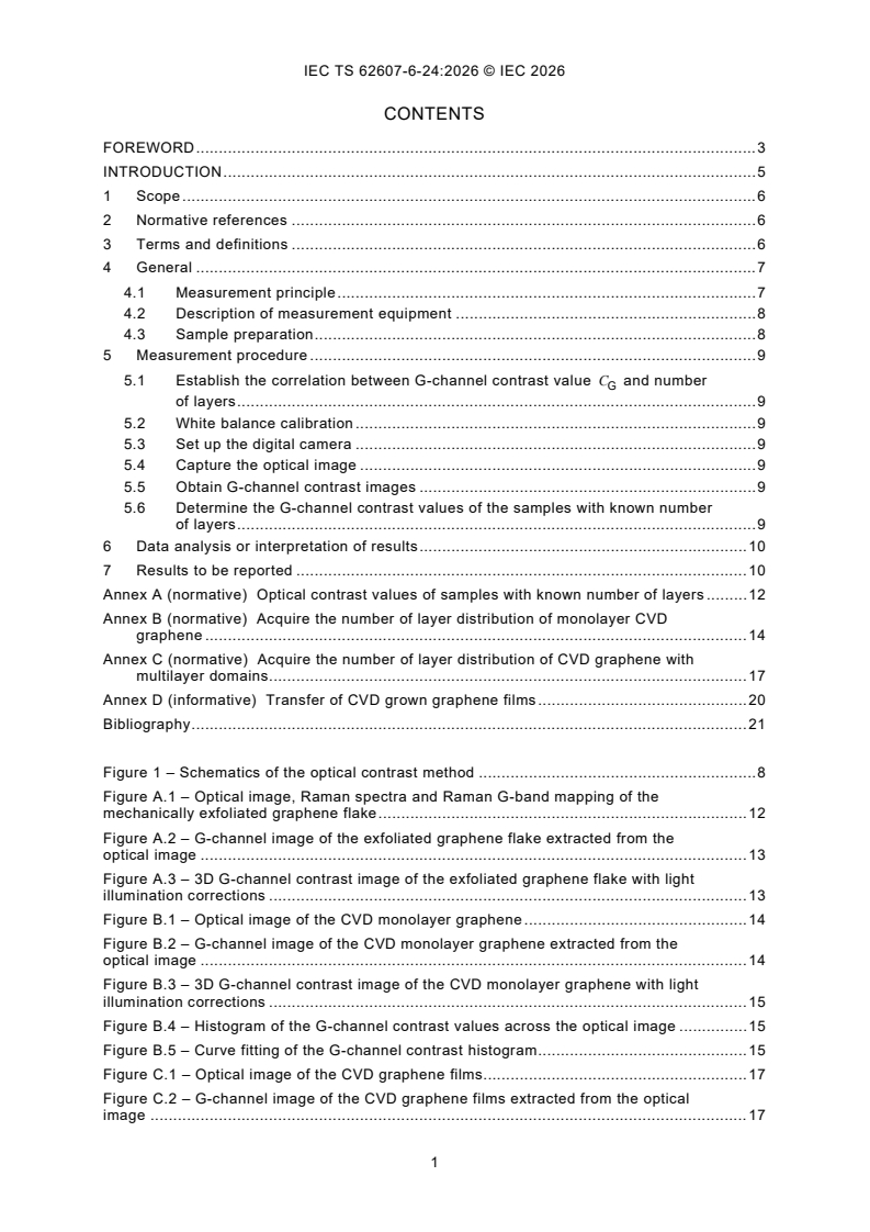
CONTENTS
FOREWORD . 3
INTRODUCTION . 5
1 Scope . 6
2 Normative references . 6
3 Terms and definitions . 6
4 General . 7
4.1 Measurement principle . 7
4.2 Description of measurement equipment . 8
4.3 Sample preparation . 8
5 Measurement procedure . 9
5.1 Establish the correlation between G-channel contrast value C and number
G
of layers . 9
5.2 White balance calibration . 9
5.3 Set up the digital camera . 9
5.4 Capture the optical image . 9
5.5 Obtain G-channel contrast images . 9
5.6 Determine the G-channel contrast values of the samples with known number
of layers . 9
6 Data analysis or interpretation of results . 10
7 Results to be reported . 10
Annex A (normative) Optical contrast values of samples with known number of layers . 12
Annex B (normative) Acquire the number of layer distribution of monolayer CVD
graphene . 14
Annex C (normative) Acquire the number of layer distribution of CVD graphene with
multilayer domains. 17
Annex D (informative) Transfer of CVD grown graphene films . 20
Bibliography . 21
Figure 1 – Schematics of the optical contrast method . 8
Figure A.1 – Optical image, Raman spectra and Raman G-band mapping of the
mechanically exfoliated graphene flake . 12
Figure A.2 – G-channel image of the exfoliated graphene flake extracted from the
optical image . 13
Figure A.3 – 3D G-channel contrast image of the exfoliated graphene flake with light
illumination corrections . 13
Figure B.1 – Optical image of the CVD monolayer graphene . 14
Figure B.2 – G-channel image of the CVD monolayer graphene extracted from the
optical image . 14
Figure B.3 – 3D G-channel contrast image of the CVD monolayer graphene with light
illumination corrections . 15
Figure B.4 – Histogram of the G-channel contrast values across the optical image . 15
Figure B.5 – Curve fitting of the G-channel contrast histogram . 15
Figure C.1 – Optical image of the CVD graphene films. 17
Figure C.2 – G-channel image of the CVD graphene films extracted from the optical
image . 17
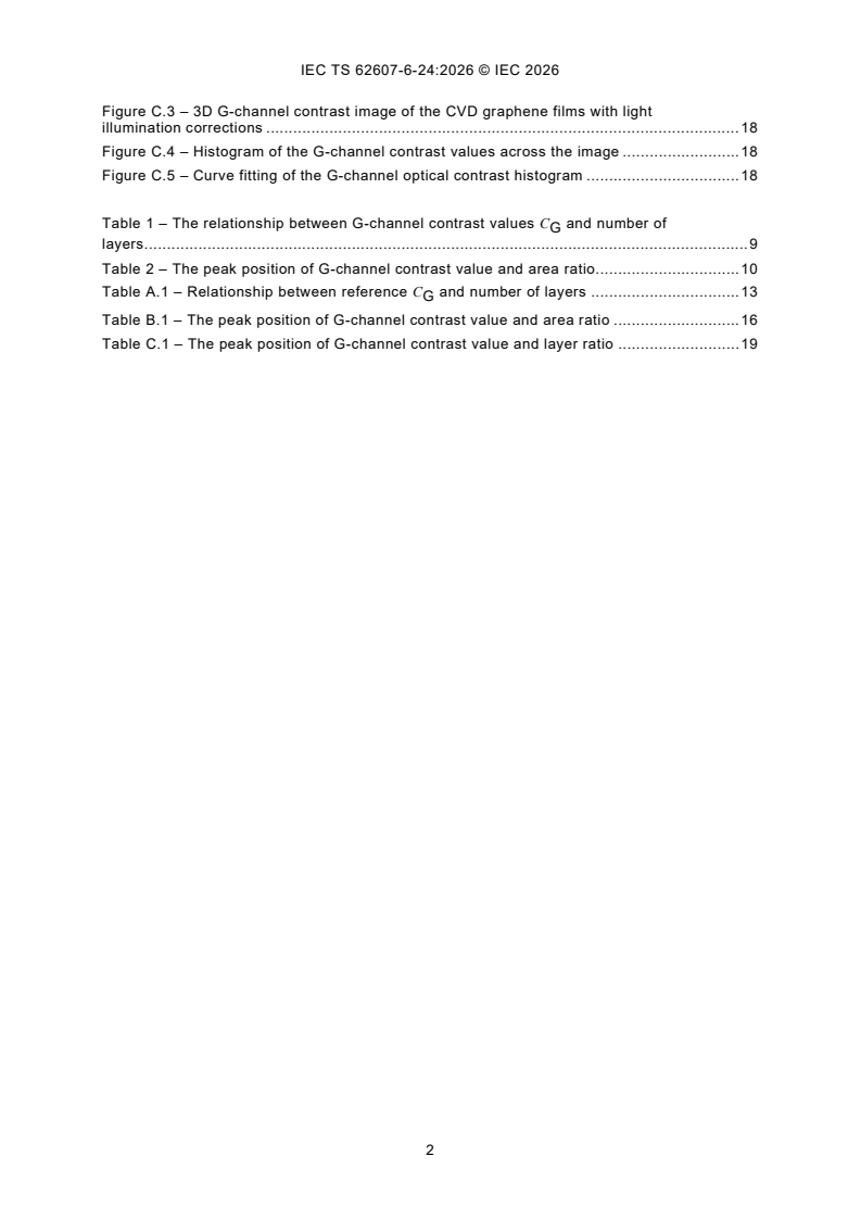
Figure C.3 – 3D G-channel contrast image of the CVD graphene films with light
illumination corrections . 18
Figure C.4 – Histogram of the G-channel contrast values across the image . 18
Figure C.5 – Curve fitting of the G-channel optical contrast histogram . 18
Table 1 – The relationship between G-channel contrast values C and number of
G
layers. 9
Table 2 – The peak position of G-channel contrast value and area ratio . 10
Table A.1 – Relationship between reference C and number of layers . 13
G
Table B.1 – The peak position of G-channel contrast value and area ratio . 16
Table C.1 – The peak position of G-channel contrast value and layer ratio . 19
INTERNATIONAL ELECTROTECHNICAL COMMISSION
____________
Nanomanufacturing - Key control characteristics -
Part 6-24: Graphene-related products -
Number of layers of graphene: optical contrast
FOREWORD
1) The International Electrotechnical Commission (IEC) is a worldwide organization for standardization comprising
all national electrotechnical committees (IEC National Committees). The object of IEC is to promote international
co-operation on all questions concerning standardization in the electrical and electronic fields. To this end and
in addition to other activities, IEC publishes International Standards, Technical Specifications, Technical Reports,
Publicly Available Specifications (PAS) and Guides (hereafter referred to as "IEC Publication(s)"). Their
preparation is entrusted to technical committees; any IEC National Committee interested in the subject dealt with
may participate in this preparatory work. International, governmental and non-governmental organizations liaising
with the IEC also participate in this preparation. IEC collaborates closely with the International Organization for
Standardization (ISO) in accordance with conditions determined by agreement between the two organizations.
2) The formal decisions or agreements of IEC on technical matters express, as nearly as possible, an international
consensus of opinion on the relevant subjects since each technical committee has representation from all
interested IEC National Committees.
3) IEC Publications have the form of recommendations for international use and are accepted by IEC National
Committees in that sense. While all reasonable efforts are made to ensure that the technical content of IEC
Publications is accurate, IEC cannot be held responsible for the way in which they are used or for any
misinterpretation by any end user.
4) In order to promote international uniformity, IEC National Committees undertake to apply IEC Publications
transparently to the maximum extent possible in their national and regional publications. Any divergence between
any IEC Publication and the corresponding national or regional publication shall be clearly indicated in the latter.
5) IEC itself does not provide any attestation of conformity. Independent certification bodies provide conformity
assessment services and, in some areas, access to IEC marks of conformity. IEC is not responsible for any
services carried out by independent certification bodies.
6) All users should ensure that they have the latest edition of this publication.
7) No liability shall attach to IEC or its directors, employees, servants or agents including individual experts and
members of its technical committees and IEC National Committees for any personal injury, property damage or
other damage of any nature whatsoever, whether direct or indirect, or for costs (including legal fees) and
expenses arising out of the publication, use of, or reliance upon, this IEC Publication or any other IEC
Publications.
8) Attention is drawn to the Normative references cited in this publication. Use of the referenced publications is
indispensable for the correct application of this publication.
9) IEC draws attention to the possibility that the implementation of this document may involve the use of (a)
patent(s). IEC takes no position concerning the evidence, validity or applicability of any claimed patent rights in
respect thereof. As of the date of publication of this document, IEC had not received notice of (a) patent(s), which
may be required to implement this document. However, implementers are cautioned that this may not represent
the latest information, which may be obtained from the patent database available at https://patents.iec.ch. IEC
shall not be held responsible for identifying any or all such patent rights.
IEC TS 62607-6-24 has been prepared by IEC technical committee 113: Nanotechnology for
electrotechnical products and systems. It is a Technical Specification.
The text of this Technical Specification is based on the following documents:
Draft Report on voting
113/952/DTS 113/979/RVDTS
Full information on the voting for its approval can be found in the report on voting indicated in
the above table.
The language used for the development of this Technical Specification is English.
This document was drafted in accordance with ISO/IEC Directives, Part 2, and developed in
accordance with ISO/IEC Directives, Part 1 and ISO/IEC Directives, IEC Supplement, available
at www.iec.ch/members_experts/refdocs. The main document types developed by IEC are
described in greater detail at www.iec.ch/publications.
A list of all parts of the IEC 62607 series, published under the general title Nanomanufacturing -
Key control characteristics, can be found on the IEC website.
The committee has decided that the contents of this document will remain unchanged until the
stability date indicated on the IEC website under webstore.iec.ch in the data related to the
specific document. At this date, the document will be
– reconfirmed,
– withdrawn, or
– revised.
INTRODUCTION
Graphene, as a pioneer of 2D materials, plays a critical role in many state-of-the-art applications,
extensively involving electronics, optoelectronics, sensors, and energy storage. [1] Graphene
has many desirable properties, e.g. high carrier mobility, broadband optical absorption,
biocompatibility and excellent stability and hence has good prospects not only for basic
research but also for various industrial applications. Large-area graphene film fabricated by
chemical vapour deposition (CVD) method is one of the most promising candidates for
commercialization. However, large-area CVD graphene films typically contain multilayer
domains that occupy varying proportions of the surface area, which can significantly affect their
electrical, mechanical and optical properties. Therefore, it is crucial to quantitatively assess
number of layer distribution (i.e. the area proportions for various layer domains) in CVD
graphene films for both research and application development.
There are many approaches for measuring number of layers of graphene films, such as
transmission electron microscopy (TEM), Raman spectroscopy, optical microscopy, and atomic
force microscopy (AFM). However, how to measure number of layer distribution is not specified
yet. This will affect application development and commercialization of large-area CVD graphene
film.
This document specifies a simple, high-throughput, and non-destructive approach to measure
number of layer distribution of large-area CVD graphene film by optical contrast method. The
basic principle and experimental approach of the optical contrast method are presented to
identify number of layer distribution. This method relies on the statistical analysis of the optical
contrast values of the pixels that make up the sample's optical images, and it is significantly
more efficient than TEM, AFM and Raman spectroscopy characterization method. With light
illumination corrections, the coverage ratio of monolayer and multilayer domains in large-scale
CVD graphene can be obtained accurately.
___________
Numbers in square brackets refer to the Bibliography.
1 Scope
This part of IEC 62607 establishes a standardized method to determine the key control
characteristic (KCC)
– number of layer distribution
for CVD graphene film by
– optical contrast measurement
The number of layers and number of layer distribution of CVD graphene film is derived by
G-channel contrast values.
This method is applicable for clean CVD graphene film without twisted multilayer structures on
a SiO /Si substrate.
2 Normative references
The following documents are referred to in the text in such a way that some or all of their content
constitutes requirements of this document. For dated references, only the edition cited applies.
For undated references, the latest edition of the referenced document (including any
amendments) applies.
IEC TS 62607-6-11:2022, Nanomanufacturing - Key control characteristics - Part 6-11:
Graphene - Defect density: Raman spectroscopy
3 Terms and definitions
For the purposes of this document, the following terms and definitions apply.
ISO and IEC maintain terminology databases for use in standardization at the following
addresses:
– IEC Electropedia: available at https://www.electropedia.org/
– ISO Online browsing platform: available at https://www.iso.org/obp
3.1
optical contrast value
C
normalized difference in reflected light intensity between the blank substrate and the sample
on the substrate
II−
substrate sample
C=
(1)
I
substrate
where
is the reflected light intensity of the blank substrate;
I
substrate
I is the reflected light intensity of the sample on the substrate.
sample
3.2
G-channel value
value extracted from green channel (G-channel) at each pixel in the optical image
Note 1 to entry: The G-channel value is in the range 0 to 255.
3.3
G-channel contrast value
C
G
normalized difference in G-channel value between the blank substrate and the sample on the
substrate
GG−
substrate sample
C =
(2)
G
G
substrate
where
G and G are the G-channel values at each pixel taken from the substrate and
substrate sample
graphene film regions, respectively.
4 General
4.1 Measurement principle
Optical image of graphene film contains the information of reflected light. Graphene films with
different number of layers or different thicknesses exhibit different RGB channel values shown
in the optical images. [2] Particularly, for graphene film deposited on a 300 nm SiO2/Si substrate,
theoretical analysis and experimental results have demonstrated that among the RGB channels,
the G-channel value shows the largest variation with the increasing number of layers of
graphene film. [3] Hence, it is reasonable to define optical contrast value (Formula (1)) and use
G-channel contrast value (Formula (2)) as an indicator to identify the number of layers of
graphene film. The number of layer distr
...