

ISO/FDIS 3405
(Main)Petroleum and related products from natural or synthetic sources — Determination of distillation characteristics at atmospheric pressure
- Abstract
This document specifies a laboratory method for the determination of the distillation characteristics of light and middle distillates derived from petroleum and related products of synthetic or biological origin with initial boiling points above 0 °C and end-points below approximately 400 °C, utilizing either manual or automated equipment. Light distillates are typically automotive engine petrol, automotive engine ethanol fuel blends with up to 85 % (V/V) ethanol, and aviation petrol. Middle distillates are typically aviation turbine fuel, kerosene, diesel, diesel with up to 30 % (V/V) FAME, burner fuel, and marine fuels that have no appreciable quantities of residua. NOTE For the purposes of this document, the term "% (V/V)" is used to represent the volume fraction of a material. The distillation (volatility) characteristics of hydrocarbons and related products of synthetic or biological origin have an important effect on their safety and performance, especially in the case of fuels and solvents. The boiling range gives important information on composition and behaviour during storage and use, and the rate of evaporation is an important factor in the application of many solvents. Limiting values to specified distillation characteristics are applied to most distillate petroleum product and liquid fuel specifications in order to control end-use performance and to regulate the formation of vapours which may form explosive mixtures with air, or otherwise escape into the atmosphere as emissions (VOC).
- Status
- Not Published
- Technical Committee
- ISO/TC 28 - Petroleum and related products, fuels and lubricants from natural or synthetic sources
- Drafting Committee
- ISO/TC 28/WG 26 - Physio-chemical and inspection tests
- Current Stage
- 5020 - FDIS ballot initiated: 2 months. Proof sent to secretariat
- Start Date
- 28-Oct-2026
- Completion Date
- 28-Oct-2026
Buy Documents
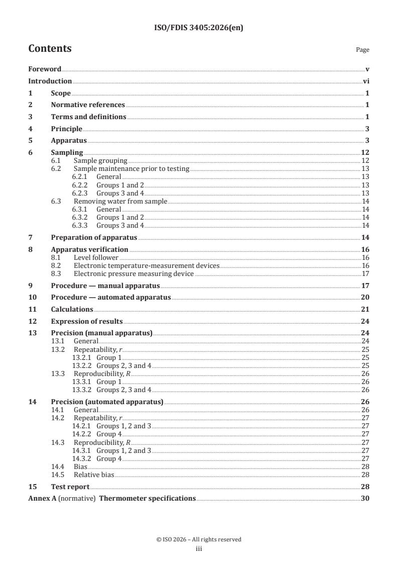
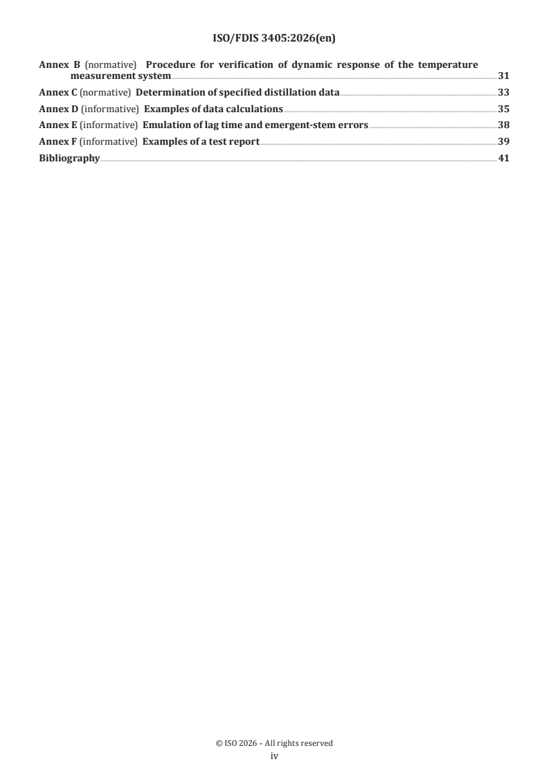
ISO/FDIS 3405 - Petroleum and related products from natural or synthetic sources — Determination of distillation characteristics at atmospheric pressure
REDLINE ISO/FDIS 3405 - Petroleum and related products from natural or synthetic sources — Determination of distillation characteristics at atmospheric pressure
ISO/FDIS 3405 is an ISO draft International Standard for determining the distillation characteristics of light and middle distillates at atmospheric pressure. It specifies a laboratory method for petroleum and related products of synthetic or biological origin, using manual or automated equipment, so users can compare fuel and solvent volatility against product specifications.
What does ISO/FDIS 3405 specify?
ISO/FDIS 3405 specifies a laboratory distillation method for products with initial boiling points above 0 °C and end-points below approximately 400 °C. The scope covers light and middle distillates such as automotive engine petrol, aviation petrol, aviation turbine fuel, kerosene, diesel, diesel with up to 30 % (V/V) FAME, burner fuel, special petroleum spirits, naphthas, white spirits, and marine fuels with no appreciable quantities of residua.
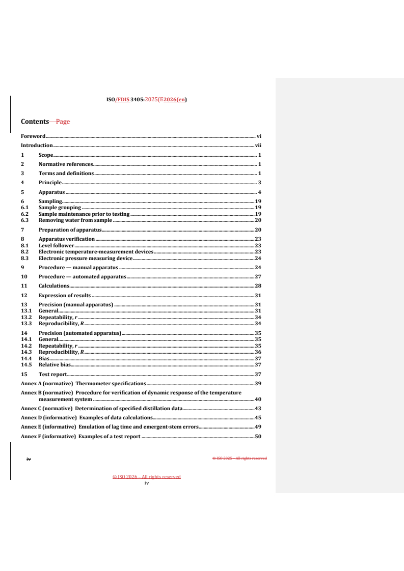
The document is organized into clauses 1 to 15, followed by six annexes. Annexes A, B and C are normative and define thermometer specifications, verification of temperature response, and the procedure for specified distillation data. Annexes D, E and F are informative and give calculation examples, temperature-response emulation guidance, and example test reports.
| Annex | What it covers |
|---|---|
| A | Thermometer specifications |
| B | Procedure for verification of dynamic response of the temperature measurement system |
| C | Determination of specified distillation data |
| D | Examples of data calculations |
| E | Emulation of lag time and emergent-stem errors |
| F | Examples of a test report |
What are the key requirements of ISO/FDIS 3405?
Clause 4 assigns the sample to one of four groups based on composition and expected volatility. In practice, this choice drives the flask arrangement, condenser temperature, and operating conditions, so the same product type is always tested under the same type of setup.
Clause 6 requires sampling in accordance with ISO 3170 or ISO 3171, with special handling by group. Samples must be kept at the specified temperatures, and visibly hazy or water-containing samples must be dried or replaced, because suspended water can distort the distillation curve.
Clause 7 and Table 2 define how to prepare the apparatus before testing. The operator selects the correct flask, temperature-measurement system, and support board for the group, then brings the flask, receiver, sensor, and cooling bath to the required starting temperatures.
Clause 5 and Annex A set the apparatus requirements, including the 125 ml flask, 100 ml receiving cylinder, residue cylinder, condenser, barometer, and temperature sensor. For automated apparatus, the unit also needs automatic fire shut-down and inert gas or vapour discharge, which matters because the test uses heated flammable liquids.
Clause 8 and Annex B require verification of the measurement system. Electronic temperature-measurement devices must match the lag and emergent-stem behavior of mercury-in-glass thermometers, and the dynamic response is checked with suitable check standards; this is what makes automated results comparable with manual results.
Clauses 9 and 10 separate the manual and automated procedures. Both require controlled heating, observation of initial boiling point, control of condensation rate, checks at the 5 ml residue point, and repeat testing if the required timing or condensation conditions are not met.
Clause 11 gives the calculation rules. Temperature readings are corrected to 101,3 kPa unless a specification says otherwise, and the document then defines how to calculate corrected loss, corrected recovery, and percentages evaporated or recovered from the measured curve.
Clauses 12, 13 and 14 control reporting and precision. The report must identify the procedure used, the pressure basis, whether values are based on evaporated or recovered volume, and any special handling such as dried samples or substituted thermometers; the precision statements then show the expected repeatability and reproducibility for manual and automated apparatus.
Annex C is used when a specification asks for values such as E70 or R200 instead of a full distillation curve. It tells the user how to work around the target temperature, interpolate the result, and report the specified distillation data.
What terms does ISO/FDIS 3405 define?
Initial boiling point (IBP) - the corrected thermometer reading observed when the first drop of condensate falls from the condenser tube.
Final boiling point (FBP) / end point - the maximum corrected thermometer reading obtained during the test.
Dry point - the corrected reading at which the last drop of liquid evaporates from the lowest point in the flask, ignoring film or drops left on the sidewall or thermometer.
Percent recovered - the volume of condensate observed in the receiving cylinder at a given time, expressed as a percentage of the charge volume.
Percent loss - the calculated amount of uncondensed material lost during the distillation, sometimes called front-end loss.
Temperature lag - the offset between a mercury-in-glass thermometer and an electronic temperature-measurement device caused by different response times.
Check standard - a material with an accepted reference value used to determine the accuracy of a measurement system.
Who uses ISO/FDIS 3405?
ISO/FDIS 3405 is used by laboratory personnel, fuel and petroleum quality managers, and producers or blenders who need to verify distillation performance against product specifications. It is also used by test laboratories handling petrol, aviation fuels, kerosene, diesel, burner fuels, marine fuels, and related solvents, as well as by manufacturers and verifiers of automated distillation equipment. In practice, users apply it for product qualification, batch comparison, specification compliance testing, and instrument verification.
What changed in ISO/FDIS 3405 from the previous edition?
ISO/FDIS 3405 is the sixth edition and it cancels and replaces ISO 3405:2019.
- Annex B has been replaced with a procedure for verification of dynamic response of the temperature measurement system from ASTM D86.
- Related information has been added in the appropriate clauses and annexes.
- Clause 5.8.2 now includes the use of verified electronic temperature devices as referee.
- Clause 8.2 has revised procedures for verification of temperature measurement.
Which standards are used with ISO/FDIS 3405?
| Standard | What it contributes |
|---|---|
| ISO 918 | Reference method for distillation characteristics of volatile organic liquids for industrial use |
| ISO 3170 | Manual sampling of petroleum liquids |
| ISO 3171 | Automatic pipeline sampling of petroleum liquids |
| ISO 4788 | Laboratory glassware, including the graduated cylinders used in the test |
| ISO 4259-1 | Statistical treatment used for precision statements in Clauses 13 and 14 |
| ISO 17034 | Competence requirements for producers of the reference materials used in Annex B |
| ISO 17035 | Guidance for validation and verification programmes used for secondary working standards |
| ISO 33401 | Certificates, labels and accompanying documentation for reference materials |
| ISO 33403 | Requirements and recommendations for using reference materials |
| ASTM D86 | Source of the reprinted Annex B procedure and related supporting material |
What does the ISO/FDIS 3405 document contain?
ISO/FDIS 3405 contains the full laboratory method, including apparatus descriptions, sampling conditions, preparation steps, manual and automated procedures, calculation formulas, and reporting rules. It also includes multiple tables for sample grouping, test conditions, pressure corrections, slope points, and precision, which users rely on for routine testing and dispute resolution.
The document includes figures showing the manual and automated apparatus assemblies, flask details, condenser end geometry, centring devices, and thermometer position. Annex A gives thermometer specifications, Annex B gives the dynamic-response verification procedure and check-standard tables, and Annex C gives the method for specified distillation data.
Annex D works through example calculations, Annex E explains how temperature lag and emergent-stem effects can be emulated, and Annex F shows example test reports. Together, these parts support method setup, instrument verification, result calculation, and reporting in laboratory and conformity-assessment work.
Relations
- Effective Date
- 12-Feb-2026
- Effective Date
- 15-Mar-2025
Buy Documents
ISO/FDIS 3405 - Petroleum and related products from natural or synthetic sources — Determination of distillation characteristics at atmospheric pressure
REDLINE ISO/FDIS 3405 - Petroleum and related products from natural or synthetic sources — Determination of distillation characteristics at atmospheric pressure
Get Certified
Connect with accredited certification bodies for this standard

Element Materials Technology
Materials testing and product certification.

ABS Group Brazil
ABS Group certification services in Brazil.

ABS Quality Evaluations Inc.
American Bureau of Shipping quality certification.
Sponsored listings
Frequently Asked Questions
ISO/FDIS 3405 is a draft published by the International Organization for Standardization (ISO). Its full title is "Petroleum and related products from natural or synthetic sources — Determination of distillation characteristics at atmospheric pressure". This standard covers: This document specifies a laboratory method for the determination of the distillation characteristics of light and middle distillates derived from petroleum and related products of synthetic or biological origin with initial boiling points above 0 °C and end-points below approximately 400 °C, utilizing either manual or automated equipment. Light distillates are typically automotive engine petrol, automotive engine ethanol fuel blends with up to 85 % (V/V) ethanol, and aviation petrol. Middle distillates are typically aviation turbine fuel, kerosene, diesel, diesel with up to 30 % (V/V) FAME, burner fuel, and marine fuels that have no appreciable quantities of residua. NOTE For the purposes of this document, the term "% (V/V)" is used to represent the volume fraction of a material. The distillation (volatility) characteristics of hydrocarbons and related products of synthetic or biological origin have an important effect on their safety and performance, especially in the case of fuels and solvents. The boiling range gives important information on composition and behaviour during storage and use, and the rate of evaporation is an important factor in the application of many solvents. Limiting values to specified distillation characteristics are applied to most distillate petroleum product and liquid fuel specifications in order to control end-use performance and to regulate the formation of vapours which may form explosive mixtures with air, or otherwise escape into the atmosphere as emissions (VOC).
This document specifies a laboratory method for the determination of the distillation characteristics of light and middle distillates derived from petroleum and related products of synthetic or biological origin with initial boiling points above 0 °C and end-points below approximately 400 °C, utilizing either manual or automated equipment. Light distillates are typically automotive engine petrol, automotive engine ethanol fuel blends with up to 85 % (V/V) ethanol, and aviation petrol. Middle distillates are typically aviation turbine fuel, kerosene, diesel, diesel with up to 30 % (V/V) FAME, burner fuel, and marine fuels that have no appreciable quantities of residua. NOTE For the purposes of this document, the term "% (V/V)" is used to represent the volume fraction of a material. The distillation (volatility) characteristics of hydrocarbons and related products of synthetic or biological origin have an important effect on their safety and performance, especially in the case of fuels and solvents. The boiling range gives important information on composition and behaviour during storage and use, and the rate of evaporation is an important factor in the application of many solvents. Limiting values to specified distillation characteristics are applied to most distillate petroleum product and liquid fuel specifications in order to control end-use performance and to regulate the formation of vapours which may form explosive mixtures with air, or otherwise escape into the atmosphere as emissions (VOC).
ISO/FDIS 3405 is classified under the following ICS (International Classification for Standards) categories: 75.160.20 - Liquid fuels. The ICS classification helps identify the subject area and facilitates finding related standards.
ISO/FDIS 3405 has the following relationships with other standards: It is inter standard links to FprEN ISO 3405, ISO 3405:2019. Understanding these relationships helps ensure you are using the most current and applicable version of the standard.
ISO/FDIS 3405 is available in PDF format for immediate download after purchase. The document can be added to your cart and obtained through the secure checkout process. Digital delivery ensures instant access to the complete standard document.
Standards Content (Sample)
FINAL DRAFT
International
Standard
ISO/TC 28
Petroleum and related products
Secretariat: NEN
from natural or synthetic sources —
Voting begins on:
Determination of distillation
2026-10-28
characteristics at atmospheric
Voting terminates on:
pressure
2026-12-09
Produits pétroliers et connexes d'origine naturelle ou
synthétique — Détermination des caractéristiques de distillation
à pression atmosphérique
RECIPIENTS OF THIS DRAFT ARE INVITED TO SUBMIT,
WITH THEIR COMMENTS, NOTIFICATION OF ANY
RELEVANT PATENT RIGHTS OF WHICH THEY ARE AWARE
AND TO PROVIDE SUPPOR TING DOCUMENTATION.
IN ADDITION TO THEIR EVALUATION AS
BEING ACCEPTABLE FOR INDUSTRIAL, TECHNO
ISO/CEN PARALLEL PROCESSING LOGICAL, COMMERCIAL AND USER PURPOSES, DRAFT
INTERNATIONAL STANDARDS MAY ON OCCASION HAVE
TO BE CONSIDERED IN THE LIGHT OF THEIR POTENTIAL
TO BECOME STAN DARDS TO WHICH REFERENCE MAY BE
MADE IN NATIONAL REGULATIONS.
Reference number
FINAL DRAFT
International
Standard
ISO/TC 28
Petroleum and related products
Secretariat: NEN
from natural or synthetic sources —
Voting begins on:
Determination of distillation
characteristics at atmospheric
Voting terminates on:
pressure
Produits pétroliers et connexes d'origine naturelle ou
synthétique — Détermination des caractéristiques de distillation
à pression atmosphérique
© ISO 2026
All rights reserved.
RECIPIENTS OF THIS DRAFT ARE INVITED TO SUBMIT,
WITH THEIR COMMENTS, NOTIFICATION OF ANY
This ISO publication is protected by copyright and is owned by ISO and/or its licensors.
RELEVANT PATENT RIGHTS OF WHICH THEY ARE AWARE
The content of this ISO publication is provided under licence, not sold. Use is subject to the applicable licence terms issued by ISO,
AND TO PROVIDE SUPPOR TING DOCUMENTATION.
an ISO member body, or an authorized third-party distributor.
IN ADDITION TO THEIR EVALUATION AS
BEING ACCEPTABLE FOR INDUSTRIAL, TECHNO
Except as required for implementation or expressly permitted by a separate licence, no part of this ISO publication may be
ISO/CEN PARALLEL PROCESSING
LOGICAL, COMMERCIAL AND USER PURPOSES, DRAFT
reproduced, distributed, modified, used, or made available in any form or by any means – electronic or mechanical, including
INTERNATIONAL STANDARDS MAY ON OCCASION HAVE
photocopying, scanning, recording, or posting on internal or external digital platforms. TO BE CONSIDERED IN THE LIGHT OF THEIR POTENTIAL
TO BECOME STAN DARDS TO WHICH REFERENCE MAY BE
Any use beyond the scope of the granted rights is prohibited and may result in legal action.
MADE IN NATIONAL REGULATIONS.
ISO copyright office
CP 401 • CH-1214 Vernier, Geneva
Phone: +41 22 749 01 11
Email: copyright@iso.org
Website: www.iso.org
Published in Switzerland
Reference number
ii
Contents Page
Foreword .v
Introduction .vi
1 Scope . 1
2 Normative references . 1
3 Terms and definitions . 1
4 Principle . 3
5 Apparatus . 3
6 Sampling .12
6.1 Sample grouping . 12
6.2 Sample maintenance prior to testing . 13
6.2.1 General . 13
6.2.2 Groups 1 and 2 . 13
6.2.3 Groups 3 and 4 . 13
6.3 Removing water from sample .14
6.3.1 General .14
6.3.2 Groups 1 and 2 .14
6.3.3 Groups 3 and 4 .14
7 Preparation of apparatus . 14
8 Apparatus verification .16
8.1 Level follower .16
8.2 Electronic temperature-measurement devices.16
8.3 Electronic pressure measuring device .17
9 Procedure — manual apparatus . 17
10 Procedure — automated apparatus .20
11 Calculations .21
12 Expression of results .24
13 Precision (manual apparatus) .24
13.1 General .24
13.2 Repeatability, r. 25
13.2.1 Group 1 . 25
13.2.2 Groups 2, 3 and 4 . 25
13.3 Reproducibility, R . 26
13.3.1 Group 1 . 26
13.3.2 Groups 2, 3 and 4 . 26
14 Precision (automated apparatus) .26
14.1 General . 26
14.2 Repeatability, r.27
14.2.1 Groups 1, 2 and 3 .27
14.2.2 Group 4 .27
14.3 Reproducibility, R .27
14.3.1 Groups 1, 2 and 3 .27
14.3.2 Group 4 .27
14.4 Bias . 28
14.5 Relative bias . 28
15 Test report .28
Annex A (normative) Thermometer specifications .30
iii
Annex B (normative) Procedure for verification of dynamic response of the temperature
measurement system .31
Annex C (normative) Determination of specified distillation data .33
Annex D (informative) Examples of data calculations .35
Annex E (informative) Emulation of lag time and emergent-stem errors .38
Annex F (informative) Examples of a test report .39
Bibliography . 41
iv
Foreword
ISO (the International Organization for Standardization) is a worldwide federation of national standards
bodies (ISO member bodies). The work of preparing International Standards is normally carried out through
ISO technical committees. Each member body interested in a subject for which a technical committee
has been established has the right to be represented on that committee. International organizations,
governmental and non-governmental, in liaison with ISO, also take part in the work. ISO collaborates closely
with the International Electrotechnical Commission (IEC) on all matters of electrotechnical standardization.
The procedures used to develop this document and those intended for its further maintenance are described
in the ISO/IEC Directives, Part 1. In particular, the different approval criteria needed for the different types
of ISO document should be noted. This document was drafted in accordance with the editorial rules of the
ISO/IEC Directives, Part 2 (see www.iso.org/directives).
ISO draws attention to the possibility that the implementation of this document may involve the use of (a)
patent(s). ISO takes no position concerning the evidence, validity or applicability of any claimed patent
rights in respect thereof. As of the date of publication of this document, ISO had not received notice of (a)
patent(s) which may be required to implement this document. However, implementers are cautioned that
this may not represent the latest information, which may be obtained from the patent database available at
www.iso.org/patents. ISO shall not be held responsible for identifying any or all such patent rights.
Any trade name used in this document is information given for the convenience of users and does not
constitute an endorsement.
For an explanation of the voluntary nature of standards, the meaning of ISO specific terms and expressions
related to conformity assessment, as well as information about ISO's adherence to the World Trade
Organization (WTO) principles in the Technical Barriers to Trade (TBT), see www.iso.org/iso/foreword.html.
This document was prepared by Technical Committee ISO/TC 28, Petroleum and related products, fuels and
lubricants from natural or synthetic sources, in collaboration with the European Committee for Standardization
(CEN) Technical Committee CEN/TC 19, Gaseous and liquid fuels, lubricants and related products of petroleum,
synthetic and biological origin, in accordance with the Agreement on technical cooperation between ISO and
CEN (Vienna Agreement).
This sixth edition cancels and replaces the fifth edition (ISO 3405:2019), which has been technically revised.
The main changes are as follows:
— Annex B has been replaced with the Procedure for verification of dynamic response of the temperature
measurement system from ASTM D86; relevant information has been added in appropriate clauses and
annexes.
— in 5.7.2, use of verified electronic temperature devices as referee has been included;
— in 8.2, procedures on verification of temperature measurement have been revised.
Any feedback or questions on this document should be directed to the user’s national standards body. A
complete listing of these bodies can be found at www.iso.org/members.html.
v
Introduction
The distillation (volatility) characteristics of hydrocarbons and related products of synthetic or biological
origin have an important effect on their safety and performance, especially in the case of fuels and solvents.
The boiling range gives important information on composition and behaviour during storage and use, and
the rate of evaporation is an important factor in the application of many solvents. Limiting values to specified
distillation characteristics are applied to most distillate petroleum product and liquid fuel specifications in
order to control end-use performance and to regulate the formation of vapours which can form explosive
mixtures with air, or otherwise escape into the atmosphere as emissions (VOC).
vi
FINAL DRAFT International Standard ISO/FDIS 3405:2026(en)
Petroleum and related products from natural or synthetic
sources — Determination of distillation characteristics at
atmospheric pressure
WARNING — The use of this document can involve hazardous materials, operations and equipment.
This document does not purport to address all the safety problems associated with its use. It is the
responsibility of users of this document to take appropriate measures to ensure the safety and
health of personnel prior to the application of the standard, and to determine the applicability of any
other restrictions for this purpose.
1 Scope
This document specifies a laboratory method for the determination of the distillation characteristics of
light and middle distillates derived from petroleum and related products of synthetic or biological origin
with initial boiling points above 0 °C and final boiling points below approximately 400 °C, utilizing either
manual or automated equipment. Light distillates are typically automotive engine petrol, automotive engine
[4]
ethanol fuel blends with a volume fraction of up to 85 % ethanol, and aviation petrol. Middle distillates are
typically aviation turbine fuel, kerosene, diesel, diesel with a volume fraction of up to 30 % fatty acid methyl
esters (FAME), burner fuel, special petroleum spirits, naphthas, white spirits, and marine fuels that have no
appreciable quantities of residua.
2 Normative references
The following documents are referred to in the text in such a way that some or all of their content constitutes
requirements of this document. For dated references, only the edition cited applies. For undated references,
the latest edition of the referenced document (including any amendments) applies.
ISO 3170, Petroleum liquids — Manual sampling
ISO 3171, Petroleum liquids — Automatic pipeline sampling
ISO 4788, Laboratory glassware — Graduated measuring cylinders
3 Terms and definitions
For the purposes of this document, the following terms and definitions apply.
ISO and IEC maintain terminology databases for use in standardization at the following addresses:
— ISO Online browsing platform: available at https:// www .iso .org/ obp
— IEC Electropedia: available at https:// www .electropedia .org/
3.1
decomposition point
thermometer reading (corrected) which coincides with the first indications of thermal decomposition of the
liquid in the flask
Note 1 to entry: Characteristic indications of thermal decomposition are an evolution of fumes and erratic thermometer
readings which usually show a decided decrease after any attempt has been made to adjust the heat.
3.2
dry point
thermometer reading (corrected) that is observed at the instant the last drop of liquid evaporates from the
lowest point in the flask, any drops or film of liquid on the side of the flask or on the thermometer being
disregarded
Note 1 to entry: The end point (final boiling point), rather than the dry point is intended for general use. The dry point
can be reported in connection with special purpose naphthas, such as those used in the paint industry. Also, it is
substituted for the end point (final boiling point) whenever the sample is of such a nature that the precision of the end
point cannot consistently meet the precision requirements given in Clauses 13 or 14.
3.3
final boiling point
end point
maximum thermometer reading (corrected) obtained during the test
Note 1 to entry: This usually occurs after evaporation of all liquid from the bottom of the flask.
3.4
initial boiling point
thermometer reading (corrected) that is observed at the instant that the first drop of condensate falls from
the lower end of the condenser tube
3.5
per cent evaporated
sum of the per cent recovered (3.8) and the per cent loss (3.6)
3.6
per cent loss
calculated amount of uncondensed material
Note 1 to entry: Sometimes called “front-end loss”; this is the amount of uncondensed material lost in the initial stages
of the distillation.
3.7
corrected loss
per cent loss (3.6) corrected for barometric pressure
3.8
per cent recovered
volume of condensate observed in the receiving cylinder at any point in the distillation, expressed as a
percentage of the charge volume, in connection with a simultaneous temperature reading
3.9
per cent recovery
maximum per cent recovered
Note 1 to entry: Examples are shown in 9.10 and 10.10.
3.10
per cent residue
volume of residue measured, and expressed as a percentage of the charge volume
Note 1 to entry: Examples are shown in 9.11 and 10.11.
3.11
per cent total recovery
combined per cent recovery and residue in the flask
Note 1 to entry: Examples are shown in 11.1.
3.12
thermometer reading
temperature recorded by the sensor of the saturated vapour measured in the neck of the flask below the
vapour tube, under the specified conditions of the test method specified in this document
3.13
temperature reading
thermometer or temperature-measurement device reading (3.12) which is corrected to 101,3 kPa standard
pressure
3.14
emergent stem effect
offset in temperature reading caused by the use of a total immersion mercury-in-glass thermometer in the
partial immersion mode
Note 1 to entry: The emergent part of the mercury column is at a lower temperature than the immersed portion,
resulting in a lower temperature reading than that obtained when the thermometer was completely immersed for
calibration.
3.15
temperature lag
offset in temperature reading between a mercury-in-glass thermometer and an electronic temperature-
measurement device, caused by the different response time of the systems involved
3.16
check standard
material having an accepted reference value used to determine the accuracy of a measurement system
4 Principle
The sample is assigned into one of four groups based on its composition and expected volatility
characteristics, each group defining the apparatus arrangement, condenser temperature and operational
variables. A 100 ml test portion is distilled under the specified conditions appropriate to the group into
which the sample falls. Systematic observations of thermometer readings and volumes of condensate
recovered are made. The volume of the residue in the flask is measured, and the loss on distillation recorded.
The thermometer readings are corrected for barometric pressure. The data are then used for calculations
appropriate to the nature of the sample and the specification requirements.
5 Apparatus
Typical assemblies of the manual apparatus are shown in Figures 1 and 2. In addition to the basic components
described in Clause 5, automated apparatuses are equipped with a system to measure and automatically
record the vapour temperature and the associated recovered volume in the receiving cylinder.
Automated equipment manufactured from 1999 onwards shall be equipped with a device to automatically
shut down power to the unit and to spray an inert gas or vapour in the chamber where the distillation flask
is mounted in the event of fire.
NOTE Some causes of fires are breakage of the distillation flask, electrical shorts, and foaming and spilling of
liquid sample through the top opening of the flask.
5.1 Distillation flasks, with a capacity of 125 ml and constructed of heat-resistant glass, in accordance
with the dimensions and tolerances shown in Figure 3.
For tests specifying the dry point, selected flasks with bottoms and walls of uniform thickness are especially
recommended.
5.2 Condenser tube and cooling bath, as illustrated in Figures 1 and 2.
Other types of apparatus may be used, provided that the test results obtained by their use correlate with the
results obtained with those illustrated, and satisfy the precision criteria given in Clauses 13 or 14.
The condenser shall be made of seamless non-corrosive metal tubing, 560 mm ± 5 mm in length, with an
outside diameter of 14 mm and a wall thickness of 0,8 mm to 0,9 mm.
NOTE Brass or stainless steel are suitable materials.
The condenser shall be set so that 393 mm ± 3 mm of the tube is in contact with the cooling medium, with
50 mm ± 3 mm outside the cooling bath at the upper end, and 114 mm ± 3 mm outside at the lower end. The
portion of tube projecting at the upper end shall be set at an angle of 75° ± 3° to the vertical. The portion of
the tube inside the cooling bath shall be either straight or bent in any suitable continuous smooth curve. The
average gradient shall be 15° ± 1° with respect to the horizontal, and no 100 mm section shall have a gradient
outside a 15° ± 3° range. The projecting lower portion of the condenser tube shall be curved downward for
a length of 76 mm and the lower end cut off at an acute angle. Provisions shall be made to enable the flow of
distillate to run down the side of the receiving cylinder. Figure 4 gives an illustration of the lower end of the
condenser tube.
The flow of distillate down the side of the graduated cylinder can be accomplished either by using a drip-
deflector which is inserted in the receiver, or by having the downward length of the condenser tube curve
slightly backwards so as to ensure contact with the wall of the receiving cylinder at a point 25 mm to 32 mm
below the top of the receiving cylinder when it is in position to receive distillate.
The volume and design of the cooling bath will depend on the cooling medium employed. The cooling capacity
of the bath shall be adequate to maintain the required temperature for the desired condenser performance.
A single cooling bath may be used for several condenser tubes.
5.3 Metal shield or enclosure for flask (manual apparatus only), provided to protect the distillation
flask from draughts. They shall allow easy access to the distillation during operation and be provided with
at least one window to observe the dry point at the end of the distillation.
NOTE 1 A typical shield for a unit fitted with a gas burner would be 480 mm high, 280 mm long and 200 mm wide,
made of sheet metal approximately 0,8 mm in thickness (see Figure 1).
NOTE 2 A typical shield for a unit fitted with an electric heater would be 440 mm high, 200 mm long and 200 mm
wide, made of sheet metal approximately 0,8 mm in thickness (see Figure 2).
Key
1 cooling bath
2 air vents
3 burner
4 shield
5 heat-resistant boards
6 distillation flask
7 thermometer
8 bath cover
9 blotting paper
10 support
11 graduated cylinder
12 gas line
Figure 1 — Apparatus assembly using a gas burner
Key
1 receiving cylinder
2 blotting paper
3 thermometer
4 distillation flask
5 flask-support board
6 electric heating element
7 flask-support platform
8 flask-adjusting knob
9 indicating dial
10 switch
11 open bottom shield
12 cooling bath
13 condenser tube
14 shield
Figure 2 — Apparatus assembly using an electric heater
Dimensions in millimetres
Key
1 19/22 neck or 19/26 neck
a
Reinforcing bead.
b
Fire polished.
Figure 3 — 125 ml flasks — Alternative neck designs
Dimensions in millimetres
Figure 4 — Lower end of condenser tube
5.4 Heat source(s):
5.4.1 Gas burner (see Figure 1), capable of bringing over the first drop from a cold start within the time
specified and continuing the distillation at the specified rate. A sensitive regulating valve and gas pressure
governor to give complete control of heating shall be provided.
5.4.2 Electric heater (see Figure 2), of low heat retention and adjustable from 0 W to 1 000 W.
5.5 Flask-support:
5.5.1 Type 1 for use with gas burner (see Figure 1). Either a ring support of the ordinary laboratory
type, 100 mm or larger in diameter, supported on a stand inside the shield, or a platform adjustable from the
outside of the shield shall be used.
The flask support board shall be constructed of ceramic or other heat-resistant material, 3 mm to 6 mm in
thickness and shall have a central opening conforming to the dimensions given in Table 2. The flask support
board shall be of sufficient dimension to ensure that thermal heat to the flask only comes from the central
opening and that extraneous heat to the flask other than through the central opening is minimized. The
flask-support board may be moved slightly according to the directions for positioning the distillation flask
so that direct heat is applied to the flask only through the opening in this board. The position of the flask is
set by adjusting the length of the side-arm inserted into the condenser.
5.5.2 Type 2 for use with an electric heater (see Figure 2). The flask-support is a platform on top of the
electric heater and adjustable from the outside of the shield. The flask support board described in 5.5.1 is
mounted on this support. Provision shall be made for moving the upper (flask-support) board slightly in the
horizontal plane to ensure that direct heat is applied only through the specified opening in this board. The
flask-support assembly shall be able to move vertically to ensure contact of the flask-support board with
the bottom of the distillation flask during the distillation, and to allow for easy mounting and removal of the
distillation flask from the unit.
5.6 Graduated cylinders:
5.6.1 Receiving cylinder, of 100 ml ± 1,0 ml capacity, nominally in accordance with ISO 4788. It shall
be graduated at intervals of 1 ml beginning at least at the 5 ml mark and have a graduation at the 100 ml
mark. The shape of the base shall be such that the receiver does not topple when placed empty on a surface
inclined at an angle of 13° to the horizontal. Construction details and tolerances for the graduated cylinder
are shown in Figure 5.
Dimensions in millimetres
a
Fire polished top end.
Figure 5 — 100 ml receiving cylinder (tolerance ± 1,0 ml)
For automated apparatus, the receiving cylinder shall conform to the specifications of the manufacturer of
the distillation apparatus. Receiving cylinders for use in automated units shall have a 100 ml mark and may
also have a metal base.
If required, the receiving cylinder shall be either immersed in a cooling bath containing cooling liquid, such
as a tall-form beaker of clear glass or transparent plastic, up to above the 100 ml graduation line, or placed
in a thermostatically controlled air-circulation chamber.
5.6.2 Residue cylinder, of 5 ml capacity, generally in accordance with ISO 4788.
5.7 Temperature measurement system:
5.7.1 Thermometers, if used, shall be of the mercury-in-glass type, nitrogen filled, graduated on the stem
and enamel backed, and shall conform to the specifications given in Annex A.
WARNING — Under certain test conditions, the bulb of the thermometer can be 28 °C above the
temperature indicated, and at an indicated temperature of 370 °C, the temperature of the bulb
is approaching a critical range in the glass. It is thus strongly recommended that distillation
temperature readings above 370 °C are avoided, but in those cases where thermometers have been
exposed to observed temperature readings above 370 °C, they shall not be re-used without checking
their ice point to verify calibration.
5.7.2 Electronic temperature-measurement devices, if used, shall exhibit the same temperature lag,
emergent stem effect and equal or better accuracy as the equivalent mercury-in-glass thermometer.
To simulate the temperature lag and emergent stem effect of a mercury-in-glass thermometer, the circuitry
or the algorithms, or both, used for the electronic system, shall take this fact into account (see Annex E). A
procedure for verification of the dynamic response of the temperature measurement system is described in
Annex B.
Alternatively, place the sensor in a casing with the tip covered, so that the assembly, because of its adjusted
thermal mass and conductivity, has a temperature lag and emergent stem effect similar to that of mercury-
in-glass thermometers.
In case of dispute between results using a mercury-in-glass thermometer versus a properly verified
temperature measuring system that has been verified through the procedures described in 8.2 and Annex B,
unless otherwise agreed, the referee test shall be carried out using the properly verified temperature
measuring system specified in this test method.
5.8 Centring device. The temperature sensor shall be fitted through a snug-fitting device designed for
mechanically centring the sensor in the neck of the distillation flask without vapour leakage. The use of a
cork or silicone rubber stopper with a hole drilled through the centre is not acceptable for this purpose.
Examples of acceptable centring devices are shown in Figures 6 and 7.
When running tests by the manual method, products with a low initial boiling point can have one or more
temperature readings obscured by the centring device.
Centring devices not shown in Figures 6 and 7 are also acceptable provided they position and hold the
temperature sensor in the middle of the neck of the distillation flask.
5.9 Barometer, capable of measuring atmospheric pressure with an accuracy of 0,1 kPa or better, at the
same elevation relative to sea level as the apparatus in the laboratory. Do not take readings from aneroid
barometers that are pre-corrected to give sea level pressures.
The barometer should ideally be located in the room in which the distillation is carried out.
Key
1 O-ring
a
Screwcap.
b
Knurled knob.
c
Cone male NS 19/26.
Figure 6 — PTFE centring device for ground-glass joint
Key
1 single O-ring Viton or perfluoro elastomer
2 compression nut (PTFE)
3 PTFE body
4 double O-rings Viton or perfluoro elastomer
5 compression O-ring
6 compression nut
7 thermometer or Pt 100 probe
8 neck of distilling flask
a
Cone-shaped for perfect centring in neck of distillation flask.
b
Drilled out to fit Pt 100 probe.
c
Compression without O-ring.
d
Threads.
e
Flask neck (inside).
Figure 7 — Two illustrative centring device designs for straight-bore neck
6 Sampling
6.1 Sample grouping
Determine the nature of the product to be sampled and place it in the appropriate group according to Table 1,
which also gives general guidance on sampling conditions.
6.2 Sample maintenance prior to testing
6.2.1 General
Unless otherwise specified, sampling shall be carried out by the procedures described in ISO 3170 or
ISO 3171, bearing in mind the special conditions described in Table 1. Maintain samples prior to testing at
the specified temperatures given in Table 1, away from sources of direct heat or sunlight.
6.2.2 Groups 1 and 2
Collect the sample in a container previously cooled to below 10 °C, when necessary. Condition the container
preferably by immersing it in the liquid, where possible, and discarding the first sample. Where immersion
is not possible, the sample shall be drawn off into the previously cooled container in such a manner that
agitation is kept at a minimum. Close the container immediately with a tight-fitting stopper and place the
sample in an ice bath or refrigerator to maintain the sample below the specified temperature. Maintain the
sample below 10 °C prior to testing, and preferably store at or below this temperature. Where maintenance
and/or storage at below 10 °C is not possible or practicable, a temperature up to 20 °C is acceptable provided
that the sample is always conditioned to a temperature below 10 °C before the container is opened.
6.2.3 Groups 3 and 4
Maintain the sample at ambient temperature. If the sample is not fluid at ambient temperature, maintain it
at a temperature of 9 °C to 21 °C above its pour point. Shake the sample vigorously prior to subsampling to
ensure homogeneity and disregard the temperature range shown in Table 2 for the receiving cylinder. Prior
to analysis, heat the receiving cylinder to approximately the same temperature as the sample, and pour the
heated test portion precisely to the 100 ml mark. Transfer the test portion as rapidly and completely as
possible to the distillation flask.
WARNING — A tightly-sealed, full, cold container of sample is likely to break if heated.
Table 1 — Sample groups and sampling conditions
Group number 1 2 3 4
Typical sample type Gasoline Gasoline Wide-cut Kerosene/
aviation fuel gas oil
Vapour pressure, dry ≥ 65,5 < 65,5 < 65,5 < 65,5
vapour pressure equiva-
lent (DVPE), kPa
Initial boiling point — — ≤ 100 > 100
(IBP), °C
Final boiling point ≤ 250 ≤ 250 > 250 > 250
(FBP), °C
Temperature of sample < 10 — — —
bottle, °C
a a
Temperature of sample ≤ 10 ≤ 10 Ambient Ambient
at sampling, °C
b b
Temperature of stored < 10 < 10 Ambient Ambient
sample, °C
If sample is wet Resample or dry Resample or dry Dry Dry
(Reference) (6.3.2) (6.3.2) (6.3.3) (6.3.3)
a
Samples shall always be at 9 °C to 21 °C above their pour point if not fluid at ambient temperature.
b
When no facilities are available for storage below 10 °C, the sample may be stored below 20 °C provided the container is
tightly sealed. See 6.2.2.
6.3 Removing water from sample
6.3.1 General
Samples of materials that are visibly hazy (suspended water) or are suspected of containing water are not
suitable for testing.
6.3.2 Groups 1 and 2
If the sample is not dry, obtain another sample for testing that is free from suspended water. If such a sample
cannot be obtained, add a sufficient amount of anhydrous sodium sulfate or other suitable drying agent to
the sample maintained at 0 °C to 10 °C, and physically remove the water by shaking. Once the sample shows
no visible signs of water, use a decanted portion of the sample, maintained at 0 °C to 10 °C, for the analysis.
Record that the sample has been dried by desiccant.
Data from an interlaboratory exercise show that suspended water in hazy samples in group 1 and group 2
may be removed by the above procedure without statistically affecting the results of the test.
6.3.3 Groups 3 and 4
In cases where a water-free sample is not practical, remove the suspended water by shaking the sample
with anhydrous sodium sulfate or another suitable drying agent, and separate it from the drying agent by
decantation.
7 Preparation of apparatus
7.1 Refer to Table 2 and prepare the apparatus by choosing the appropriate distillation flask, temperature-
measurement system and flask-support board as directed for the indicated group. If gas heating is used,
use a type 1 flask-support (5.5.1); if electric heating is used, use a type 2 flask-support (5.5.2). Bring the
temperature of the receiving cylinder, the flask, the temperature sensor and the cooling bath to the indicated
temperature.
7.2 Make any necessary provisions so that the temperature of the cooling bath and receiving cylinder are
maintained at their specified temperatures. The receiving cylinder shall be positioned in a bath such that
either the liquid level is at least as high as the 100 ml mark, or the entire receiving cylinder is surrounded by
an air-circulation chamber.
For groups 1, 2 and 3, use suitable media for low temperature baths such as chopped ice and water,
refrigerated brine and refrigerated ethylene glycol.
For group 4, use suitable media for ambient and higher bath temperatures such as cold water, hot water and
heated ethylene glycol.
7.3 Remove any residual liquid in the condenser tube by swabbing with a piece of soft, lint-free cloth
attached to a cord or wire.
7.4 For samples in groups 1, 2 and 3, fit a low-range temperature sensor, provided with a snug-fitting cork
or silicone rubber stopper, tightly into the neck of the sample container, and bring the temperature of the
sample to that specified in Table 2.
Table 2 — Preparation of apparatus
Group number 1 2 3 4
Temperature-measurement system (see 5.7) Low-range Low-range Low-range High-range
Diameter of hole in flask-support board, mm 38 38 50 50
Temperature at start of test, °C
— flask and thermometer 13 to 18 13 to 18 13 to 18 ≤ ambient
— flask-support board and shield ≤ ambient ≤ ambient ≤ ambient —
— receiving cylinder and sample 13 to 18 13 to 18 13 to 18 13 to ambient
7.5 When the temperature of the sample is confirmed, measure the test portion precisely to the 100 ml
mark of the receiving cylinder, and then transfer it as completely as practical to the distillation flask, taking
care that none of the liquid flows into the vapour tube.
NOTE 1 Any material which evaporates during the transfer will contribute to the loss; any material which remains
in the receiving cylinder will contribute to the observed recovery volume at the time of the initial boiling point.
If irregular boiling (bumping) is expected, add a small volume of clean and dry boiling chips to the test
portion.
NOTE 2 Although theoretically the volume of deposit on the chips is part of the residue, this amount is negligible
and can be disregarded.
7.6 Fit the appropriate temperature sensor through a centring device (
...
ISO/DIS FDIS 3405:2027(en)
ISO/TC 28
Secretariat: NEN
Date: 2026-07-1310-14
Petroleum and related products from natural or synthetic
sources — Determination of distillation characteristics at
atmospheric pressure
Produits pétroliers et connexes d'origine naturelle ou synthétique — Détermination des caractéristiques de
distillation à pression atmosphérique
TThhiiss d drraftaft i iss s suubbmmiitttteded t too a pa pararallel vallel vootte e iinn I ISSOO,, C CEENN.
© FDIS stage
ISO/DIS FDIS 3405:20272026(en)
All rights reserved. Unless otherwise specified,
This ISO publication is protected by copyright and is owned by ISO and/or its licensors.
The content of this ISO publication is provided under licence, not sold. Use is subject to the applicable licence terms issued
by ISO, an ISO member body, or an authorized third-party distributor.
Except as required in the context of its for implementation or expressly permitted by a separate licence, no part of this
ISO publication may be reproduced or utilized otherwise, distributed, modified, used, or made available in any form or
by any means, – electronic or mechanical, including photocopying, scanning, recording, or posting on internal or external
digital platforms.
Any use beyond the internet or an intranet, without prior written permission. Permission can be requested from either
ISO at the address below or ISO’s member body in the countryscope of the requestergranted rights is prohibited and may
result in legal action.
ISO copyright office
CP 401 • Ch. de Blandonnet 8
CH-1214 Vernier, Geneva
Phone: + 41 22 749 01 11
Email: copyright@iso.org
Website: www.iso.org
Published in Switzerland
iii
Contents Page
Foreword . vi
Introduction . vii
1 Scope . 1
2 Normative references . 1
3 Terms and definitions . 1
4 Principle . 3
5 Apparatus . 4
6 Sampling . 19
6.1 Sample grouping . 19
6.2 Sample maintenance prior to testing . 19
6.3 Removing water from sample . 20
7 Preparation of apparatus . 20
8 Apparatus verification . 23
8.1 Level follower . 23
8.2 Electronic temperature-measurement devices . 23
8.3 Electronic pressure measuring device . 24
9 Procedure — manual apparatus . 24
10 Procedure — automated apparatus . 27
11 Calculations . 28
12 Expression of results . 31
13 Precision (manual apparatus) . 31
13.1 General. 31
13.2 Repeatability, r . 34
13.3 Reproducibility, R . 34
14 Precision (automated apparatus) . 35
14.1 General. 35
14.2 Repeatability, r . 35
14.3 Reproducibility, R . 36
14.4 Bias . 37
14.5 Relative bias . 37
15 Test report . 37
Annex A (normative) Thermometer specifications . 39
Annex B (normative) Procedure for verification of dynamic response of the temperature
measurement system . 40
Annex C (normative) Determination of specified distillation data . 43
Annex D (informative) Examples of data calculations. 45
Annex E (informative) Emulation of lag time and emergent-stem errors . 49
Annex F (informative) Examples of a test report . 50
iv
iv
ISO/DIS FDIS 3405:20272026(en)
Bibliography . 55
v
Foreword
ISO (the International Organization for Standardization) is a worldwide federation of national standards
bodies (ISO member bodies). The work of preparing International Standards is normally carried out through
ISO technical committees. Each member body interested in a subject for which a technical committee has been
established has the right to be represented on that committee. International organizations, governmental and
non-governmental, in liaison with ISO, also take part in the work. ISO collaborates closely with the
International Electrotechnical Commission (IEC) on all matters of electrotechnical standardization.
The procedures used to develop this document and those intended for its further maintenance are described
in the ISO/IEC Directives, Part 1. In particular, the different approval criteria needed for the different types of
ISO document should be noted. This document was drafted in accordance with the editorial rules of the
ISO/IEC Directives, Part 2 (see www.iso.org/directives).
ISO draws attention to the possibility that the implementation of this document may involve the use of (a)
patent(s). ISO takes no position concerning the evidence, validity or applicability of any claimed patent rights
in respect thereof. As of the date of publication of this document, ISO had not received notice of (a) patent(s)
which may be required to implement this document. However, implementers are cautioned that this may not
represent the latest information, which may be obtained from the patent database available at
www.iso.org/patents. ISO shall not be held responsible for identifying any or all such patent rights.
Any trade name used in this document is information given for the convenience of users and does not
constitute an endorsement.
For an explanation of the voluntary nature of standards, the meaning of ISO specific terms and expressions
related to conformity assessment, as well as information about ISO's adherence to the World Trade
Organization (WTO) principles in the Technical Barriers to Trade (TBT), see www.iso.org/iso/foreword.html.
This document was prepared by Technical Committee ISO/TC 28, Petroleum and related products, fuels and
lubricants from natural or synthetic sources, in collaboration with the European Committee for Standardization
(CEN) Technical Committee CEN/TC 19, Gaseous and liquid fuels, lubricants and related products of petroleum,
synthetic and biological origin, in accordance with the Agreement on technical cooperation between ISO and
CEN (Vienna Agreement).
This sixth edition cancels and replaces the fifth edition (ISO 3405:2019), which has been technically revised.
The main changes are as follows:
— Annex B— Annex B has been replaced with the Procedure for verification of dynamic response of the
temperature measurement system from ASTM D86. Relevant; relevant information has been added in
appropriate clauses and annexes.
— — in 5.7.25.8.2,, use of verified electronic temperature devices as referee has been included;
— — in 8.28.2,, procedures on verification of temperature measurement have been revised.
Any feedback or questions on this document should be directed to the user’s national standards body. A
complete listing of these bodies can be found at www.iso.org/members.html.
vi
vi
ISO/DIS FDIS 3405:20272026(en)
Introduction
The distillation (volatility) characteristics of hydrocarbons and related products of synthetic or biological
origin have an important effect on their safety and performance, especially in the case of fuels and solvents.
The boiling range gives important information on composition and behaviour during storage and use, and the
rate of evaporation is an important factor in the application of many solvents. Limiting values to specified
distillation characteristics are applied to most distillate petroleum product and liquid fuel specifications in
order to control end-use performance and to regulate the formation of vapours which can form explosive
mixtures with air, or otherwise escape into the atmosphere as emissions (VOC).
vii
DRAFT International Standard ISO/DIS 3405:2027(en)
Petroleum and related products from natural or synthetic sources —
Determination of distillation characteristics at atmospheric pressure
WARNING — The use of this document can involve hazardous materials, operations and equipment.
This document does not purport to address all the safety problems associated with its use. It is the
responsibility of users of this document to take appropriate measures to ensure the safety and health
of personnel prior to the application of the standard, and to determine the applicability of any other
restrictions for this purpose.
1 Scope
This document specifies a laboratory method for the determination of the distillation characteristics of light
and middle distillates derived from petroleum and related products of synthetic or biological origin with initial
boiling points above 0 °C and final boiling points below approximately 400 °C, utilizing either manual or
automated equipment. Light distillates are typically automotive engine petrol, automotive engine ethanol fuel
[4] [4]
blends with up toa volume fraction of up to 85 % ethanol, , and aviation petrol. Middle distillates are
typically aviation turbine fuel, kerosene, diesel, diesel with up toa volume fraction of up to 30 % fatty acid
methyl esters (FAME,), burner fuel, special petroleum spirits, naphthas, white spirits, and marine fuels that
have no appreciable quantities of residua.
2 Normative references
The following documents are referred to in the text in such a way that some or all of their content constitutes
requirements of this document. For dated references, only the edition cited applies. For undated references,
the latest edition of the referenced document (including any amendments) applies.
ISO 918, Volatile organic liquids for industrial use — Determination of distillation characteristics
ISO 3170, Petroleum liquids — Manual sampling
ISO 3171, Petroleum liquids — Automatic pipeline sampling
ISO 4788, Laboratory glassware — Graduated measuring cylinders
3 Terms and definitions
For the purposes of this document, the following terms and definitions apply.
ISO and IEC maintain terminology databases for use in standardization at the following addresses:
— — ISO Online browsing platform: available at https://www.iso.org/obp
— — IEC Electropedia: available at https://www.electropedia.org/
3.1 3.1
decomposition point
thermometer reading (corrected) which coincides with the first indications of thermal decomposition of the
liquid in the flask
Note 1 to entry: Characteristic indications of thermal decomposition are an evolution of fumes and erratic thermometer
readings which usually show a decided decrease after any attempt has been made to adjust the heat.
3.2 3.2
dry point
thermometer reading (corrected) that is observed at the instant the last drop of liquid evaporates from the
lowest point in the flask, any drops or film of liquid on the side of the flask or on the thermometer being
disregarded.
Note 1 to entry: The end point (final boiling point), rather than the dry point is intended for general use. The dry point
can be reported in connection with special purpose naphthas, such as those used in the paint industry. Also, it is
substituted for the end point (final boiling point) whenever the sample is of such a nature that the precision of the end
point cannot consistently meet the precision requirements given in Clauses 13Clauses 13 or 1414.
3.3 3.3
final boiling point
end point
maximum thermometer reading (corrected) obtained during the test
Note 1 to entry: This usually occurs after evaporation of all liquid from the bottom of the flask.
3.4 3.4
initial boiling point
thermometer reading (corrected) that is observed at the instant that the first drop of condensate falls from
the lower end of the condenser tube
3.5
3.5 percent
per cent evaporated
sum of the percentper cent recovered (3.8(3.8)) and the percentper cent loss (3.6(3.6))
3.6
3.6 percent
per cent loss
calculated amount of uncondensed material
Note 1 to entry: Sometimes called “front-end loss”; this is the amount of uncondensed material lost in the initial stages of
the distillation.
3.53.7 3.7
corrected loss
percentper cent loss (3.6 (3.6)) corrected for barometric pressure
3.8
3.8 percent
per cent recovered
volume of condensate observed in the receiving cylinder at any point in the distillation, expressed as a
percentage of the charge volume, in connection with a simultaneous temperature reading
3.9
3.9 percent
per cent recovery
maximum percentper cent recovered
Note 1 to entry: Examples are shown in 9.109.10 and 10.1010.10.
ISO/DISFDIS 3405:20252026(en)
3.10
3.10 percent
per cent residue
volume of residue measured, and expressed as a percentage of the charge volume
Note 1 to entry: Examples are shown in 9.119.11 and 10.1110.11.
3.11
3.11 percent
per cent total recovery
combined percentper cent recovery and residue in the flask
Note 1 to entry: Examples are shown in 11.111.1.
3.63.12 3.12
thermometer reading
temperature recorded by the sensor of the saturated vapour measured in the neck of the flask below the
vapour tube, under the specified conditions of the test method specified in this document.
3.73.13 3.13
temperature reading
thermometer or temperature-measurement device reading (3.12(3.12)) which is corrected to 101,3 kPa
standard pressure
3.83.14 3.14
emergent stem effect
offset in temperature reading caused by the use of a total immersion mercury-in-glass thermometer in the
partial immersion mode
Note 1 to entry: The emergent part of the mercury column is at a lower temperature than the immersed portion, resulting
in a lower temperature reading than that obtained when the thermometer was completely immersed for calibration.
3.93.15 3.15
temperature lag
offset in temperature reading between a mercury-in-glass thermometer and an electronic temperature-
measurement device, caused by the different response time of the systems involved
3.103.16 3.16
check standard
material having an accepted reference value used to determine the accuracy of a measurement system
4 Principle
The sample is assigned into one of four groups based on its composition and expected volatility characteristics,
each group defining the apparatus arrangement, condenser temperature and operational variables. A 100 ml
test portion is distilled under the specified conditions appropriate to the group into which the sample falls,
and systematic. Systematic observations of thermometer readings and volumes of condensate recovered are
made. The volume of the residue in the flask is measured, and the loss on distillation recorded. The
thermometer readings are corrected for barometric pressure, and the. The data are then used for calculations
appropriate to the nature of the sample and the specification requirements.
5 Apparatus
5.1 General
Typical assemblies of the manual apparatus are shown in Figures 1Figures 1 and 22. In addition to the basic
components described in Clause 5Clause 5,, automated apparatuses are equipped with a system to measure
and automatically record the vapour temperature and the associated recovered volume in the receiving
cylinder.
Automated equipment manufactured from 1999 onwards shall be equipped with a device to automatically
shut down power to the unit and to spray an inert gas or vapour in the chamber where the distillation flask is
mounted in the event of fire.
NOTE Some causes of fires are breakage of the distillation flask, electrical shorts, and foaming and spilling of liquid
sample through the top opening of the flask.
5.2 Distillation flasks
5.35.1 The distillation flasks shall have, with a capacity of 125 ml and be constructed of heat-resistant
glass, according toin accordance with the dimensions and tolerances shown in Figure 3Figure 3.
For tests specifying the dry point, selected flasks with bottoms and walls of uniform thickness are especially
recommended.
5.45.2 Condenser tube and cooling bath, as illustrated in Figures 1 and 2.
5.4.1 5.3.1 Typical types of condenser and cooling bath are illustrated in Figures 1 and 2.
Other types of apparatus may be used, provided that the test results obtained by their use correlate with the
results obtained with those illustrated, and satisfy the precision criteria given in Clauses 13Clauses 13 or
1414.
5.3.2 The condenser shall be made of seamless non-corrosive metal tubing, 560 mm ± 5 mm in
length, with an outside diameter of 14 mm and a wall thickness of 0,8 mm to 0,9 mm.
NOTE Brass or stainless steel are suitable materials.
5.3.3 The condenser shall be set so that 393 mm ± 3 mm of the tube is in contact with the cooling
medium, with 50 mm ± 3 mm outside the cooling bath at the upper end, and 114 mm ± 3 mm outside at the
lower end. The portion of tube projecting at the upper end shall be set at an angle of 75° ± 3° to the vertical.
The portion of the tube inside the cooling bath shall be either straight or bent in any suitable continuous
smooth curve. The average gradient shall be 15° ± 1° with respect to the horizontal, and no 100 mm section
shall have a gradient outside a 15° ± 3° range. The projecting lower portion of the condenser tube shall be
curved downward for a length of 76 mm and the lower end cut off at an acute angle. Provisions shall be made
to enable the flow of distillate to run down the side of the receiving cylinder. Figure 4Figure 4 gives an
illustration of the lower end of the condenser tube.
The flow of distillate down the side of the graduated cylinder can be accomplished either by using a drip-
deflector which is inserted in the receiver, or by having the downward length of the condenser tube curve
slightly backwards so as to ensure contact with the wall of the receiving cylinder at a point 25 mm to 32 mm
below the top of the receiving cylinder when it is in position to receive distillate.
5.3.4 The volume and design of the cooling bath will depend on the cooling medium employed. The
cooling capacity of the bath shall be adequate to maintain the required temperature for the desired condenser
performance. A single cooling bath may be used for several condenser tubes.
ISO/DISFDIS 3405:20252026(en)
5.5 Metal shield or enclosure for flask (manual apparatus only)
5.65.3 Shields shall be), provided to protect the distillation flask from draughts. They shall allow easy
access to the distillation during operation and be provided with at least one window to observe the dry point
at the end of the distillation.
NOTE 1 A typical shield for a unit fitted with a gas burner would be 480 mm high, 280 mm long and 200 mm wide,
made of sheet metal approximately 0,8 mm in thickness (see Figure 1Figure 1).).
NOTE 2 A typical shield for a unit fitted with an electric heater would be 440 mm high, 200 mm long and 200 mm
wide, made of sheet metal approximately 0,8 mm in thickness (see Figure 2Figure 2).).
ISO/DISFDIS 3405:20252026(en)
Key
1 cooling bath
2 air vents
3 burner
4 shield
5 heat-resistant boards
6 distillation flask
7 thermometer
8 bath cover
9 blotting paper
10 support
11 graduated cylinder
12 gas line
Figure 1 — Apparatus assembly using a gas burner
ISO/DISFDIS 3405:20252026(en)
Key
1 receiving cylinder
2 blotting paper
3 thermometer
4 distillation flask
5 flask-support board
6 electric heating element
7 flask-support platform
8 flask-adjusting knob
9 indicating dial
10 switch
11 open bottom shield
12 cooling bath
13 condenser tube
14 shield
Figure 2 — Apparatus assembly using an electric heater
ISO/DISFDIS 3405:20252026(en)
Dimensions in millimetres
Key
1 19/22 neck or 19/26 neck
a
Reinforcing bead.
b
Fire polished.
Figure 3 — 125 ml flasks — Alternative neck designs
Dimensions in millimetres
Figure 4 — Lower end of condenser tube
5.75.4 Heat source(s)):
5.7.15.4.1 5.5.1 Gas burner (see Figure 1Figure 1),), capable of bringing over the first drop
from a cold start within the time specified and continuing the distillation at the specified rate. A sensitive
regulating valve and gas pressure governor to give complete control of heating shall be provided.
5.7.25.4.2 5.5.2 Electric heater (see Figure 2Figure 2),), of low heat retention and adjustable
from 0 W to 1 000 W.
5.85.5 Flask-support:
5.8.15.5.1 5.6.1 Type 1 for use with gas burner (see Figure 1Figure 1).). Either a ring support
of the ordinary laboratory type, 100 mm or larger in diameter, supported on a stand inside the shield, or a
platform adjustable from the outside of the shield shall be used.
ISO/DISFDIS 3405:20252026(en)
The flask support board shall be constructed of ceramic or other heat-resistant material, 3 mm to 6 mm in
thickness and shall have a central opening conforming to the dimensions given in Table 2Table 2. The flask
support board shall be of sufficient dimension to ensure that thermal heat to the flask only comes from the
central opening and that extraneous heat to the flask other than through the central opening is minimized.
The flask-support board may be moved slightly according to the directions for positioning the distillation flask
so that direct heat is applied to the flask only through the opening in this board. The position of the flask is set
by adjusting the length of the side-arm inserted into the condenser.
5.8.25.5.2 5.6.2 Type 2 for use with an electric heater (see Figure 2Figure 2).). The flask-
support is a platform on top of the electric heater and adjustable from the outside of the shield. The flask
support board described in 5.5.15.6.1 is mounted on this support. Provision shall be made for moving the
upper (flask-support) board slightly in the horizontal plane to ensure that direct heat is applied only through
the specified opening in this board. The flask-support assembly shall be able to move vertically to ensure
contact of the flask-support board with the bottom of the distillation flask during the distillation, and to allow
for easy mounting and removal of the distillation flask from the unit.
5.95.6 Graduated cylinders:
5.9.15.6.1 5.7.1 Receiving cylinder, of 100 ml ± 1,0 ml capacity, nominally in accordance with
ISO 4788. It shall be graduated at intervals of 1 ml beginning at least at the 5 ml mark and have a graduation
at the 100 ml mark. The shape of the base shall be such that the receiver does not topple when placed empty
on a surface inclined at an angle of 13° to the horizontal. Construction details and tolerances for the graduated
cylinder are shown in Figure 5Figure 5.
Dimensions in millimetres
Key
ISO/DISFDIS 3405:20252026(en)
1 fire
a
Fire polished top end.
Figure 5 — 100 ml receiving cylinder (tolerance ± 1,0 ml)
For automated apparatus, the receiving cylinder shall conform to the specifications of the manufacturer of the
distillation apparatus. Receiving cylinders for use in automated units shall have a 100 ml mark and may also
have a metal base.
If required, the receiving cylinder shall be either immersed in a cooling bath containing cooling liquid, such as
a tall-form beaker of clear glass or transparent plastic, up to above the 100 ml graduation line, or placed in a
thermostatically controlled air-circulation chamber.
5.9.25.6.2 5.7.2 Residue cylinder, of 5 ml capacity, generally in accordance with ISO 4788.
5.105.7 Temperature measurement system:
5.10.15.7.1 5.8.1 Thermometers, if used, shall be of the mercury-in-glass type, nitrogen filled,
graduated on the stem and enamel backed, and shall conform to the specifications given in Annex AAnnex A.
WARNING — Under certain test conditions, the bulb of the thermometer can be 28 °C above the
temperature indicated, and at an indicated temperature of 370 °C, the temperature of the bulb is
approaching a critical range in the glass. It is thus strongly recommended that distillation temperature
readings above 370 °C are avoided, but in those cases where thermometers have been exposed to
observed temperature readings above 370 °C, they shall not be re-used without checking their ice
point to verify calibration.
5.10.25.7.2 5.8.2 Electronic temperature-measurement devices, if used, shall exhibit the
same temperature lag, emergent stem effect and equal or better accuracy as the equivalent mercury-in-glass
thermometer.
To simulate the temperature lag and emergent stem effect of a mercury-in-glass thermometer, the circuitry or
the algorithms, or both, used for the electronic system, shall take this fact into account, (see Annex EAnnex E.).
A procedure for verification of the dynamic response of the temperature measurement system is described in
Annex BAnnex B.
Alternatively, place the sensor in a casing with the tip covered, so that the assembly, because of its adjusted
thermal mass and conductivity, has a temperature lag and emergent stem effect similar to that of mercury-in-
glass thermometers.
In case of dispute between results using a mercury-in-glass thermometer versus a properly verified
temperature measuring system that has been verified through the procedures described in 8.28.2 and
Annex BAnnex B,, unless otherwise agreed, the referee test shall be carried out using the properly verified
temperature measuring system specified in this test method.
5.115.8 Centring device. The temperature sensor shall be fitted through a snug-fitting device
designed for mechanically centring the sensor in the neck of the distillation flask without vapour leakage. The
use of a cork or silicone rubber stopper with a hole drilled through the centre is not acceptable for this
purpose. Examples of acceptable centring devices are shown in Figures 6Figures 6 and 77.
When running tests by the manual method, products with a low initial boiling point can have one or more
temperature readings obscured by the centring device.
Centring devices not shown in Figures 6Figures 6 and 77 are also acceptable provided they position and hold
the temperature sensor in the middle of the neck of the distillation flask.
5.12 Barometer
5.135.9 The barometer shall be, capable of measuring atmospheric pressure with an accuracy of
0,1 kPa or better, at the same elevation relative to sea level as the apparatus in the laboratory. Do not take
readings from aneroid barometers that are pre-corrected to give sea level pressures.
The barometer should ideally be located in the room in which the distillation is carried out.
ISO/DISFDIS 3405:20252026(en)
Key
1 O-ring
a
Screwcap.
b
Knurled knob.
c
Cone male NS 19/26.
Figure 6 — PTFE centring device for ground-glass joint
Key
1 single O-ring Viton or perfluoro elastomer
2 compression nut (PTFE)
3 PTFE body
4 double O-rings Viton or perfluoro elastomer
ISO/DISFDIS 3405:20252026(en)
5 compression O-ring
6 compression nut
7 thermometer or Pt 100 probe
8 neck of distilling flask
a
Cone-shaped for perfect centring in neck of distillation flask.
b
Drilled out to fit Pt 100 probe.
c
Compression without O-ring.
d
Threads.
e
E Flask neck (inside)).
Figure 7 — Two illustrative centring device designs for straight-bore neck
6 Sampling
6.1 Sample grouping
Determine the nature of the product to be sampled and place it in the appropriate group according to
Table 1Table 1,, which also gives general guidance on sampling conditions.
6.2 Sample maintenance prior to testing
6.2.1 General
Unless otherwise specified, sampling shall be carried out by the procedures described in ISO 3170 or ISO 3171,
bearing in mind the special conditions described in Table 1Table 1. Maintain samples prior to testing at the
specified temperatures given in Table 1Table 1,, away from sources of direct heat or sunlight.
6.2.2 Groups 1 and 2
Collect the sample in a container previously cooled to below 10 °C, when necessary. Condition the container
preferably by immersing it in the liquid, where possible, and discarding the first sample. Where immersion is
not possible, the sample shall be drawn off into the previously cooled container in such a manner that agitation
is kept at a minimum. Close the container immediately with a tight-fitting stopper and place the sample in an
ice bath or refrigerator to maintain the sample below the specified temperature. Maintain the sample below
10 °C prior to testing, and preferably store at or below this temperature. Where maintenance and/or storage
at below 10 °C is not possible or practicable, a temperature up to 20 °C is acceptable provided that the sample
is always conditioned to a temperature below 10 °C before the container is opened.
6.2.3 Groups 3 and 4
Maintain the sample at ambient temperature. If the sample is not fluid at ambient temperature, maintain it at
a temperature of 9 °C to 21 °C above its pour point. Shake the sample vigorously prior to subsampling to
ensure homogeneity and disregard the temperature range shown in Table 2Table 2 for the receiving cylinder.
Prior to analysis, heat the receiving cylinder to approximately the same temperature as the sample, and pour
the heated test portion precisely to the 100 ml mark. Transfer the test portion as rapidly and completely as
possible to the distillation flask.
WARNING — A tightly-sealed, full, cold container of sample is likely to break if heated.
Table 1 — Sample groups and sampling conditions
Group number 1 2 3 4
Typical sample type Gasoline Gasoline Wide-cut Kerosene/
aviation fuel gas oil
Group number 1 2 3 4
Vapour pressure, dry ≥ 65,5 < 65,5 < 65,5 < 65,5
vaporvapour pressure
equivalent (DVPE), kPa
Initial boiling point — — ≤ 100 > 100
(IBP), °C
Final boiling point ≤ 250 ≤ 250 > 250 > 250
(FBP), °C
Temperature of sample < 10 — — —
bottle, °C
a a
Temperature of sample ≤ 10 ≤ 10 Ambient Ambient
at sampling, °C
b b
Temperature of stored < 10 < 10 Ambient Ambient
sample, °C
If sample is wet Resample or dry Resample or dry Dry Dry
(Reference) (6.3.2(6.3.2)) (6.3.2(6.3.2)) (6.3.3(6.3.3)) (6.3.3(6.3.3))
a Samples shall always be at 9 °C to 21 °C above their pour point if not fluid at ambient temperature.
b When no facilities are available for storage below 10 °C, the sample may be stored below 20 °C provided the container is tightly
sealed. See 6.2.26.2.2.
6.3 Removing water from sample
6.3.1 General
Samples of materials that are visibly hazy (suspended water) or are suspected of containing water are not
suitable for testing.
6.3.2 Groups 1 and 2
If the sample is not dry, obtain another sample for testing that is free from suspended water. If such a sample
cannot be obtained, add a sufficient amount of anhydrous sodium sulfate or other suitable drying agent to the
sample maintained at 0 °C to 10 °C, and physically remove the water by shaking. Once the sample shows no
visible signs of water, use a decanted portion of the sample, maintained at 0 °C to 10 °C, for the analysis. Record
that the sample has been dried by desiccant.
Data from an interlaboratory exercise show that suspended water in hazy samples in group 1 and group 2 may
be removed by the above procedure without statistically affecting the results of the test.
6.3.3 Groups 3 and 4
In cases where a water-free sample is not practical, remove the suspended water by shaking the sample with
anhydrous sodium sulphatesulfate or another suitable drying agent, and separate it from the drying agent by
decantation.
7 Preparation of apparatus
7.1 7.1 Refer to Table 2Table 2 and prepare the apparatus by choosing the appropriate distillation
flask, temperature-measurement system and flask-support board as directed for the indicated group. If gas
heating is used, use a Typetype 1 flask-support (5.5.1(5.6.1);); if electric heating is used, use a Typetype 2
flask-support (5.5.2(5.6.2).). Bring the temperature of the receiving cylinder, the flask, the temperature
sensor and the cooling bath to the indicated temperature.
ISO/DISFDIS 3405:20252026(en)
7.2 7.2 Make any necessary provisions so that the temperature of the cooling bath and receiving
cylinder will beare maintained at their specified temperatures. The receiving cylinder shall be positioned in
a bath such that either the liquid level is at least as high as the 100 ml mark, or the entire receiving cylinder is
surrounded by an air-circulation chamber.
For groups 1, 2 and 3, use suitable media for low temperature baths such as chopped ice and water,
refrigerated brine and refrigerated ethylene glycol.
For group 4, use suitable media for ambient and higher bath temperatures such as cold water, hot water and
heated ethylene glycol.
7.3 7.3 Remove any residual liquid in the condenser tube by swabbing with a piece of soft, lint-free
cloth attached to a cord or wire.
7.4 7.4 For samples in groups 1, 2 and 3, fit a low-range temperature sensor, provided with a snug-
fitting cork or silicone rubber stopper, tightly into the neck of the sample container, and bring the temperature
of the sample to that specified in Table 2Table 2.
Table 2 — Preparation of apparatus
Group number 1 2 3 4
Temperature-measurement system (see Low-range Low-range Low-range High-range
5.75.8))
Diameter of hole in flask-support board, mm 38 38 50 50
Temperature at start of test, °C
— — flask and thermometer
13 to 18 13 to 18 13 to 18 ≤ ambient
— — flask-support board and shield
≤ ambient ≤ ambient ≤ ambient —
— — receiving cylinder and sample
13 to 18 13 to 18 13 to 18 13 to ambient
7.5 7.5 When the temperature of the sample is confirmed, measure the test portion precisely to the
100 ml mark of the receiving cylinder, and then transfer it as completely as practical to the distillation flask,
taking care that none of the liquid flows into the vapour tube.
NOTE 1 Any material which evaporates during the transfer will contribute to the loss; any material which remains in
the receiving cylinder will contribute to the observed recovery volume at the time of the initial boiling point.
If irregular boiling (bumping) is expected, add a small volume of clean and dry boiling chips to the test portion.
NOTE 2 Although theoretically the volume of deposit on the chips is part of the residue, this amount is negligible and
can be disregarded.
7.6 7.6 Fit the appropriate temperature sensor through a centring device (5.8(5.9).). In the case of a
mercury-in-glass thermometer, the bulb is centred in the neck and the lower end of the capillary is level with
the highest point on the bottom of the inner wall of the vapour tube (see Figure 8Figure 8).). In the case of
a thermocouple/resistance thermometer, follow the manufacturer’s instructions as to placement so that the
sensing position will beis just below the level of the side arm of the distillation flask.
Use a small quantity of vacuum grease on the mating surface of the polytetrafluoroethylene (PTFE) centring
device to facilitate dismantling after use.
Figure 8 — Position of thermometer in distillation flask neck
7.7 7.7 Fit the flask vapour tube, provided with a snug-fitting, well-rolled cork or silicone rubber
stopper, tightly into the condenser tube. Adjust the distillation flask in a vertical position so that the vapour
tube extends into the condenser tube for a distance of 25 mm to 50 mm. Raise and adjust the flask-support
board to fit snugly against the bottom of the flask.
7.8 7.8 Place the receiving cylinder that was used to measure the test portion, without drying, fitted
with a drip deflector if necessary, into the bath under the lower end of the condenser tube so that the end of
the condenser tube is centred in the receiving cylinder and extends therein for a distance of at least 25 mm,
but not below the 100 ml mark. For manual distillations, cover the receiving cylinder closely with a piece of
blotting paper or similar material that has been cut to fit the condenser tube snugly. For automated
distillations, cover the receiving cylinder, if necessary, with the device provided with the apparatus.
7.9 7.9 Record the room temperature and prevailing barometric pressure. Proceed at once with the
distillation, as described in Clauses 9Clauses 9 or 1010.
ISO/DISFDIS 3405:20252026(en)
8 Apparatus verification
8.1 Level follower
For automated apparatus, the level follower/recording mechanism of the apparatus shall have a resolution of
0,1 ml with a maximum error of 0,3 ml between the 5 ml and 100 ml points. The calibration of the assembly
shall be verified according toin accordance with the manufacturer’s instructions at intervals of not more than
three months.
NOTE The typical verification procedure involves verifying the output with the receiving cylinder containing 5 ml
and 100 ml of material respectively.
8.2 Electronic temperature-measurement devices
8.2.1 8.2.1 Verification of the calibration of these temperature sensors shall be carried out at intervals of
not more than 6 months, and after the temperature system or temperature measuring device has been
replaced or repaired. The electronic circuit for resistance thermometers shall be verified against a standard
precision resistance. When performing this verification, ensure that any algorithms used to correct the
temperature for lag and emergent stem effect are not applied (see the manufacturer’s instructions). The
response of the temperature-measurement system itself shall be verified by the procedures described in
8.2.28.2.2, 8.2.3, 8.2.3 or 8.2.48.2.4.
8.2.2 8.2.2 Verify the calibration of the temperature measurement system by distilling reagent grade
toluene in accordance with ISO 3405 Group 1 as specified in Table 2,, or distil reagent grade hexadecane in
accor
...