

ISO/IEC 18000-61:2012
(Main)Information technology — Radio frequency identification for item management — Part 61: Parameters for air interface communications at 860 MHz to 960 MHz Type A
General Information
- Abstract
ISO/IEC 18000-61:2012 defines the air interface for radio frequency identification (RFID) devices operating in the 860 MHz to 960 MHz Industrial, Scientific, and Medical (ISM) band used in item management applications. It provides a common technical specification for RFID devices that can be used by ISO committees developing RFID application standards. It is intended to allow for compatibility and to encourage inter-operability of products for the growing RFID market in the international marketplace. It defines the forward and return link parameters for technical attributes including, but not limited to, operating frequency, operating channel accuracy, occupied channel bandwidth, maximum effective isotropic radiated power (EIRP), spurious emissions, modulation, duty cycle, data coding, bit rate, bit rate accuracy, bit transmission order, and, where appropriate, operating channels, frequency hop rate, hop sequence, spreading sequence, and chip rate. It further defines the communications protocol used in the air interface. ISO/IEC 18000-61:2012 specifies the physical and logical requirements for a passive-backscatter, Interrogator-Talks-First (ITF) systems. The system comprises Interrogators, also known as readers, and tags, also known as labels. An Interrogator receives information from a tag by transmitting a continuous-wave (CW) RF signal to the tag; the tag responds by modulating the reflection coefficient of its antenna, thereby backscattering an information signal to the Interrogator. The system is ITF, meaning that a tag modulates its antenna reflection coefficient with an information signal only after being directed to do so by an Interrogator. ISO/IEC 18000-61:2012 contains Type A. Type A is ITF. Type A uses Pulse-Interval Encoding (PIE) in the forward link and an adaptive ALOHA collision-arbitration algorithm. ISO/IEC 18000-61:2012 specifies physical interactions (the signalling layer of the communication link) between Interrogators and tags, Interrogator and tag operating procedures and commands, the collision arbitration scheme used to identify a specific tag in a multiple-tag environment.
- Status
- Published
- Publication Date
- 12-Jul-2012
- Technical Committee
- ISO/IEC JTC 1/SC 31 - Automatic identification and data capture techniques
- Drafting Committee
- ISO/IEC JTC 1/SC 31/WG 4 - Radio communications
- Current Stage
- 9093 - International Standard confirmed
- Start Date
- 30-Sep-2023
- Completion Date
- 29-Aug-2026

Overview
ISO/IEC 18000-61:2012 specifies the air interface for RFID (radio frequency identification) devices operating in the 860 MHz to 960 MHz ISM band for item management. It defines the physical and logical requirements for a passive backscatter, Interrogator‑Talks‑First (ITF) system - the reader (Interrogator) transmits a continuous‑wave (CW) RF signal and tags respond by backscattering. The standard (Type A) sets common parameters and a communications protocol intended to enable compatibility and interoperability of RFID products in global supply‑chain, retail and logistics markets.
Key topics and technical requirements
ISO/IEC 18000-61:2012 covers both forward‑link and return‑link parameters and protocol elements, including:
- Operating frequency range: 860 MHz – 960 MHz (ISM band)
- Air‑interface signalling: forward link using Pulse‑Interval Encoding (PIE); return link using FM0 encoding
- Collision arbitration: adaptive ALOHA algorithm for multi‑tag environments
- RF parameters: operating channel accuracy, occupied channel bandwidth, maximum EIRP, spurious emissions, duty cycle
- Modulation and data coding, bit rate and bit‑rate accuracy, bit transmission order
- Optional frequency mechanisms where applicable: frequency hopping, hop rate and sequence, spreading/chip rates
- Physical interactions and timing: power‑up/power‑down waveforms, forward‑to‑return and return‑to‑forward handover windows
- Protocol and command set: tag memory organisation, mandatory/optional commands (read, write, select, lock, etc.), CRC checks, tag states and round/slot definitions
- Conformance rules and disclosure of patent/licensing contacts (patent holders noted in the standard)
Practical applications and who uses it
ISO/IEC 18000-61:2012 is aimed at practitioners designing, manufacturing, testing or deploying UHF RFID systems for item management. Typical users include:
- RFID chipset and tag manufacturers implementing Type A air interfaces
- Reader (Interrogator) designers and firmware engineers
- Systems integrators in retail, warehousing, logistics, asset tracking and manufacturing
- Test labs and certification bodies validating interoperability and RF compliance
- Standards committees and application developers referencing a common air‑interface
Benefits include increased interoperability, predictable RF behaviour for large‑scale deployments, and a standard protocol for multi‑tag identification.
Related standards
- ISO/IEC 18000‑1 (reference architecture)
- ISO/IEC 18000‑6 (general UHF parameters) and other UHF Type parts (‑62, ‑63, ‑64)
- Other ISO/IEC 18000 series parts for LF, HF and 2.45 GHz RFID
Keywords: ISO/IEC 18000-61:2012, RFID, 860 MHz‑960 MHz, Type A, air interface, passive backscatter, PIE, FM0, ALOHA, EIRP, interoperability.
Relations
- Effective Date
- 25-Aug-2026
Get Certified
Connect with accredited certification bodies for this standard

BSI Group
BSI (British Standards Institution) is the business standards company that helps organizations make excellence a habit.

NYCE
Mexican standards and certification body.
Sponsored listings
Frequently Asked Questions
ISO/IEC 18000-61:2012 is a standard published by the International Organization for Standardization (ISO). Its full title is "Information technology — Radio frequency identification for item management — Part 61: Parameters for air interface communications at 860 MHz to 960 MHz Type A". This standard covers: ISO/IEC 18000-61:2012 defines the air interface for radio frequency identification (RFID) devices operating in the 860 MHz to 960 MHz Industrial, Scientific, and Medical (ISM) band used in item management applications. It provides a common technical specification for RFID devices that can be used by ISO committees developing RFID application standards. It is intended to allow for compatibility and to encourage inter-operability of products for the growing RFID market in the international marketplace. It defines the forward and return link parameters for technical attributes including, but not limited to, operating frequency, operating channel accuracy, occupied channel bandwidth, maximum effective isotropic radiated power (EIRP), spurious emissions, modulation, duty cycle, data coding, bit rate, bit rate accuracy, bit transmission order, and, where appropriate, operating channels, frequency hop rate, hop sequence, spreading sequence, and chip rate. It further defines the communications protocol used in the air interface. ISO/IEC 18000-61:2012 specifies the physical and logical requirements for a passive-backscatter, Interrogator-Talks-First (ITF) systems. The system comprises Interrogators, also known as readers, and tags, also known as labels. An Interrogator receives information from a tag by transmitting a continuous-wave (CW) RF signal to the tag; the tag responds by modulating the reflection coefficient of its antenna, thereby backscattering an information signal to the Interrogator. The system is ITF, meaning that a tag modulates its antenna reflection coefficient with an information signal only after being directed to do so by an Interrogator. ISO/IEC 18000-61:2012 contains Type A. Type A is ITF. Type A uses Pulse-Interval Encoding (PIE) in the forward link and an adaptive ALOHA collision-arbitration algorithm. ISO/IEC 18000-61:2012 specifies physical interactions (the signalling layer of the communication link) between Interrogators and tags, Interrogator and tag operating procedures and commands, the collision arbitration scheme used to identify a specific tag in a multiple-tag environment.
ISO/IEC 18000-61:2012 defines the air interface for radio frequency identification (RFID) devices operating in the 860 MHz to 960 MHz Industrial, Scientific, and Medical (ISM) band used in item management applications. It provides a common technical specification for RFID devices that can be used by ISO committees developing RFID application standards. It is intended to allow for compatibility and to encourage inter-operability of products for the growing RFID market in the international marketplace. It defines the forward and return link parameters for technical attributes including, but not limited to, operating frequency, operating channel accuracy, occupied channel bandwidth, maximum effective isotropic radiated power (EIRP), spurious emissions, modulation, duty cycle, data coding, bit rate, bit rate accuracy, bit transmission order, and, where appropriate, operating channels, frequency hop rate, hop sequence, spreading sequence, and chip rate. It further defines the communications protocol used in the air interface. ISO/IEC 18000-61:2012 specifies the physical and logical requirements for a passive-backscatter, Interrogator-Talks-First (ITF) systems. The system comprises Interrogators, also known as readers, and tags, also known as labels. An Interrogator receives information from a tag by transmitting a continuous-wave (CW) RF signal to the tag; the tag responds by modulating the reflection coefficient of its antenna, thereby backscattering an information signal to the Interrogator. The system is ITF, meaning that a tag modulates its antenna reflection coefficient with an information signal only after being directed to do so by an Interrogator. ISO/IEC 18000-61:2012 contains Type A. Type A is ITF. Type A uses Pulse-Interval Encoding (PIE) in the forward link and an adaptive ALOHA collision-arbitration algorithm. ISO/IEC 18000-61:2012 specifies physical interactions (the signalling layer of the communication link) between Interrogators and tags, Interrogator and tag operating procedures and commands, the collision arbitration scheme used to identify a specific tag in a multiple-tag environment.
ISO/IEC 18000-61:2012 is classified under the following ICS (International Classification for Standards) categories: 35.040 - Information coding; 35.040.50 - Automatic identification and data capture techniques. The ICS classification helps identify the subject area and facilitates finding related standards.
ISO/IEC 18000-61:2012 has the following relationships with other standards: It is inter standard links to CEN/TS 17402:2020. Understanding these relationships helps ensure you are using the most current and applicable version of the standard.
ISO/IEC 18000-61:2012 is available in PDF format for immediate download after purchase. The document can be added to your cart and obtained through the secure checkout process. Digital delivery ensures instant access to the complete standard document.
Standards Content (Sample)
INTERNATIONAL ISO/IEC
STANDARD 18000-61
First edition
2012-07-15
Information technology — Radio
frequency identification for item
management —
Part 61:
Parameters for air interface
communications at 860 MHz to 960 MHz
Type A
Technologies de l'information — Identification par radiofréquence
(RFID) pour la gestion d'objets —
Partie 61: Paramètres de communications d'une interface radio entre
860 MHz et 960 MHz, Type A
Reference number
©
ISO/IEC 2012
© ISO/IEC 2012
All rights reserved. Unless otherwise specified, no part of this publication may be reproduced or utilized in any form or by any means,
electronic or mechanical, including photocopying and microfilm, without permission in writing from either ISO at the address below or
ISO's member body in the country of the requester.
ISO copyright office
Case postale 56 CH-1211 Geneva 20
Tel. + 41 22 749 01 11
Fax + 41 22 749 09 47
E-mail copyright@iso.org
Web www.iso.org
Published in Switzerland
ii © ISO/IEC 2012 – All rights reserved
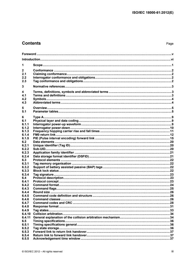
Contents Page
Foreword . v
Introduction . vi
1 Scope . 1
2 Conformance . 2
2.1 Claiming conformance . 2
2.2 Interrogator conformance and obligations . 2
2.3 Tag conformance and obligations . 2
3 Normative references . 3
4 Terms, definitions, symbols and abbreviated terms . 3
4.1 Terms and definitions . 3
4.2 Symbols . 4
4.3 Abbreviated terms . 4
5 Overview . 5
5.1 Parameter tables . 5
6 Type A . 9
6.1 Physical layer and data coding . 9
6.1.1 Interrogator power-up waveform . 9
6.1.2 Interrogator power-down . 10
6.1.3 Frequency hopping carrier rise and fall times . 11
6.1.4 FM0 return link . 12
6.1.5 PIE (Pulse interval encoding) forward link . 15
6.2 Data elements . 20
6.2.1 Unique identifier (Tag ID) . 20
6.2.2 Sub-UID. 20
6.2.3 Application family identifier . 21
6.2.4 Data storage format identifier (DSFID) . 21
6.3 Protocol elements . 22
6.3.1 Tag memory organisation . 22
6.3.2 Support of battery assisted passive (BAP) tags . 22
6.3.3 Block lock status . 22
6.3.4 Tag signature . 23
6.4 Protocol description . 23
6.4.1 Protocol concept . 23
6.4.2 Command format . 24
6.4.3 Command flags . 25
6.4.4 Round size . 26
6.4.5 Command code definition and structure . 26
6.4.6 Command classes . 26
6.4.7 Command codes and CRC . 28
6.4.8 Response format . 31
6.4.9 Tag states . 33
6.4.10 Collision arbitration . 34
6.4.11 General explanation of the collision arbitration mechanism . 34
6.5 Timing specifications . 36
6.5.1 Timing specifications general . 36
6.5.2 Tag state storage . 36
6.5.3 Forward link to return link handover . 37
6.5.4 Return link to forward link handover . 37
6.5.5 Acknowledgement time window . 37
© ISO/IEC 2012 – All rights reserved iii
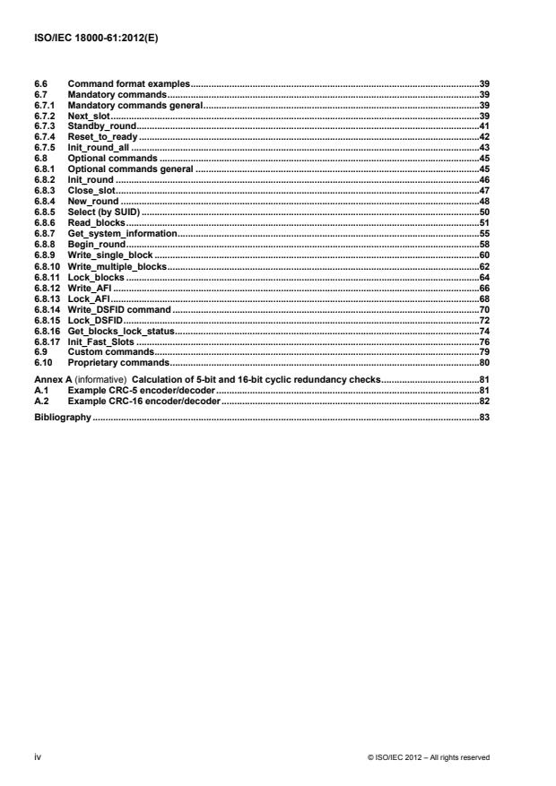
6.6 Command format examples .39
6.7 Mandatory commands .39
6.7.1 Mandatory commands general .39
6.7.2 Next_slot .39
6.7.3 Standby_round .41
6.7.4 Reset_to_ready .42
6.7.5 Init_round_all .43
6.8 Optional commands .45
6.8.1 Optional commands general .45
6.8.2 Init_round .46
6.8.3 Close_slot .47
6.8.4 New_round .48
6.8.5 Select (by SUID) .50
6.8.6 Read_blocks .51
6.8.7 Get_system_information .55
6.8.8 Begin_round .58
6.8.9 Write_single_block .60
6.8.10 Write_multiple_blocks .62
6.8.11 Lock_blocks .64
6.8.12 Write_AFI .66
6.8.13 Lock_AFI .68
6.8.14 Write_DSFID command .70
6.8.15 Lock_DSFID .72
6.8.16 Get_blocks_lock_status .74
6.8.17 Init_Fast_Slots .76
6.9 Custom commands.79
6.10 Proprietary commands .80
Annex A (informative) Calculation of 5-bit and 16-bit cyclic redundancy checks .81
A.1 Example CRC-5 encoder/decoder .81
A.2 Example CRC-16 encoder/decoder .82
Bibliography .83
iv © ISO/IEC 2012 – All rights reserved
Foreword
ISO (the International Organization for Standardization) and IEC (the International Electrotechnical
Commission) form the specialized system for worldwide standardization. National bodies that are members of
ISO or IEC participate in the development of International Standards through technical committees
established by the respective organization to deal with particular fields of technical activity. ISO and IEC
technical committees collaborate in fields of mutual interest. Other international organizations, governmental
and non-governmental, in liaison with ISO and IEC, also take part in the work. In the field of information
technology, ISO and IEC have established a joint technical committee, ISO/IEC JTC 1.
International Standards are drafted in accordance with the rules given in the ISO/IEC Directives, Part 2.
The main task of the joint technical committee is to prepare International Standards. Draft International
Standards adopted by the joint technical committee are circulated to national bodies for voting. Publication as
an International Standard requires approval by at least 75 % of the national bodies casting a vote.
ISO/IEC 18000-61 was prepared by Joint Technical Committee ISO/IEC JTC 1, Information technology,
Subcommittee SC 31, Automatic identification and data capture techniques.
ISO/IEC 18000 consists of the following parts, under the general title Information technology — Radio
frequency identification for item management:
Part 1: Reference architecture and definition of parameters to be standardized
Part 2: Parameters for air interface communications below 135 kHz
Part 3: Parameters for air interface communications at 13,56 MHz
Part 4: Parameters for air interface communications at 2,45 GHz
Part 6: Parameters for air interface communications at 860 MHz to 960 MHz General
Part 61: Parameters for air interface communications at 860 MHz to 960 MHz Type A
Part 62: Parameters for air interface communications at 860 MHz to 960 MHz Type B
Part 63: Parameters for air interface communications at 860 MHz to 960 MHz Type C
Part 64: Parameters for air interface communications at 860 MHz to 960 MHz Type D
Part 7: Parameters for active air interface communications at 433 MHz
© ISO/IEC 2012 – All rights reserved v
Introduction
This part of ISO/IEC 18000 describes a passive backscatter radio frequency identification (RFID) system that
supports the following system capabilities:
identification and communication with multiple tags in the field;
selection of a subgroup of tags for identification or with which to communicate;
reading from and writing to or rewriting data many times to individual tags;
user-controlled permanently lockable memory;
data integrity protection;
Interrogator-to-tag communications link with error detection;
tag-to-Interrogator communications link with error detection;
support for both passive back-scatter tags with or without batteries.
This part of ISO/IEC 18000 specifies the physical and logical requirements for a passive-backscatter, RFID
system operating in the 860 MHz to 960 MHz frequency range. The system comprises Interrogators, also
known as readers, and tags, also known as labels.
An Interrogator transmits information to a tag by modulating an RF signal in the 860 MHz to 960 MHz
frequency range. The tag receives both information and operating energy from this RF signal. Passive tags
are those which receive all of their operating energy from the Interrogator's RF waveform. If tags maintain a
battery then they may operate using some passive principles; however, they do not necessarily get all their
operating energy from the Interrogator's RF waveform.
An Interrogator receives information from a tag by transmitting a continuous-wave (CW) RF signal to the tag;
the tag responds by modulating the reflection coefficient of its antenna, thereby backscattering an information
signal to the Interrogator. The system is Interrogator-Talks-First (ITF), meaning that a tag modulates its
antenna reflection coefficient with an information signal only after being directed to do so by an Interrogator.
Interrogators and tags are not required to talk simultaneously; rather, communications are half-duplex,
meaning that Interrogators talk and tags listen, or vice versa.
The International Organization for Standardization (ISO) and International Electrotechnical Commission (IEC)
draw attention to the fact that it is claimed that compliance with this document may involve the use of patents
concerning radio frequency identification technology.
ISO and IEC take no position concerning the evidence, validity and scope of these patent rights.
The holders of these patent rights have assured ISO and IEC that they are willing to negotiate licences under
reasonable and non-discriminatory terms and conditions with applicants throughout the world. In this respect,
the statements of the holders of these patent rights are registered with ISO and IEC.
vi © ISO/IEC 2012 – All rights reserved
Information on the declared patents may be obtained from:
Contact details
Patent Holder Contact for license application
Legal Name: Impinj, Inc. Name & Department: Chris Diorio, CTO
Address: 701 N 34th St Suite 300, Seattle,
WA 98103, USA
Tel.: +1 206 834 1115
Fax: +1 206 517 5262
E-mail: diorio@impinj.com
URL (optional): www.impinj.com
Patent Holder Contact for license application
Legal Name: NXP B.V. Name & Department: Aaron Waxler,
Intellectual Property & Licensing
Address: 411 East Plumeria, San José, CA
95134-1924, USA
Tel.: +1 914 860 4296
E-mail: Aaron.Waxler@nxp.com
Attention is drawn to the possibility that some of the elements of this document may be the subject of patent
rights other than those identified above. ISO and IEC shall not be held responsible for identifying any or all
such patent rights.
The latest information on IP that may be applicable to this part of ISO/IEC 18000 can be found at
www.iso.org/patents
© ISO/IEC 2012 – All rights reserved vii
INTERNATIONAL STANDARD ISO/IEC 18000-61:2012(E)
Information technology — Radio frequency identification for
item management —
Part 61:
Parameters for air interface communications at 860 MHz to
960 MHz Type A
1 Scope
This part of ISO/IEC 18000 defines the air interface for radio frequency identification (RFID) devices operating
in the 860 MHz to 960 MHz Industrial, Scientific, and Medical (ISM) band used in item management
applications. It provides a common technical specification for RFID devices that can be used by ISO
committees developing RFID application standards. This part of ISO/IEC 18000 is intended to allow for
compatibility and to encourage inter-operability of products for the growing RFID market in the international
marketplace. It defines the forward and return link parameters for technical attributes including, but not limited
to, operating frequency, operating channel accuracy, occupied channel bandwidth, maximum effective
isotropic radiated power (EIRP), spurious emissions, modulation, duty cycle, data coding, bit rate, bit rate
accuracy, bit transmission order, and, where appropriate, operating channels, frequency hop rate, hop
sequence, spreading sequence, and chip rate. It further defines the communications protocol used in the air
interface.
This part of ISO/IEC 18000 specifies the physical and logical requirements for a passive-backscatter,
Interrogator-Talks-First (ITF) systems. The system comprises Interrogators, also known as readers, and tags,
also known as labels. An Interrogator receives information from a tag by transmitting a continuous-wave (CW)
RF signal to the tag; the tag responds by modulating the reflection coefficient of its antenna, thereby
backscattering an information signal to the Interrogator. The system is ITF, meaning that a tag modulates its
antenna reflection coefficient with an information signal only after being directed to do so by an Interrogator.
In detail, this part of ISO/IEC 18000 contains Type A.
Type A is ITF. Type A uses Pulse-Interval Encoding (PIE) in the forward link and an adaptive ALOHA
collision-arbitration algorithm.
This part of ISO/IEC 18000 specifies
physical interactions (the signalling layer of the communication link) between Interrogators and tags,
Interrogator and tag operating procedures and commands,
the collision arbitration scheme used to identify a specific tag in a multiple-tag environment.
© ISO/IEC 2012 – All rights reserved 1
2 Conformance
2.1 Claiming conformance
To claim conformance with this part of ISO/IEC 18000, an Interrogator or tag shall comply with all relevant
clauses of this part of ISO/IEC 18000, except those marked as “optional”. The Interrogator or tag shall also
operate within local radio regulations, which can further restrict operation.
Relevant conformance test methods are provided in ISO/IEC TR 18047-6.
Conformance can also require a license from the owner of any intellectual property utilized by said device.
2.2 Interrogator conformance and obligations
To conform to this part of ISO/IEC 18000, an Interrogator shall
support Type A
implement the mandatory commands defined in this part of ISO/IEC 18000;
modulate/transmit and receive/demodulate a sufficient set of the electrical signals defined in the signalling
layer of this part of ISO/IEC 18000 to communicate with conformant tags; and
operate within the applicable local regulations.
To conform to this part of ISO/IEC 18000, an Interrogator may
implement any subset of the optional commands defined in this part of ISO/IEC 18000, and
implement any proprietary and/or custom commands in conformance with this part of ISO/IEC 18000.
To conform to this part of ISO/IEC 18000, the Interrogator shall not
implement any command that conflicts with this part of ISO/IEC 18000 or any of the parts 62, 63 and 64,
or
require the use of an optional, proprietary, or custom command to meet the requirements of this part of
ISO/IEC 18000.
2.3 Tag conformance and obligations
To conform to this part of ISO/IEC 18000, a tag shall:
support Type A;
operate over the frequency range from 860 MHz to 960 MHz, inclusive;
implement the mandatory commands defined in this part of ISO/IEC 18000 for the supported types;
modulate a backscatter signal only after receiving the requisite command from an Interrogator; and
conform to local radio regulations.
To conform to this part of ISO/IEC 18000, a tag may
implement any subset of the optional commands defined in this part of ISO/IEC 18000; and
implement any proprietary and/or custom commands as defined in 6.9 and 6.10.
2 © ISO/IEC 2012 – All rights reserved
To conform to this part of ISO/IEC 18000, a tag shall not:
implement any command that conflicts with this part of ISO/IEC 18000 or any of the parts 62, 63 and 64;
require the use of an optional, proprietary, or custom command to meet the requirements of this part of
ISO/IEC 18000; or
modulate a backscatter signal unless commanded to do so by an Interrogator using the signalling layer
defined in this part of ISO/IEC 18000.
3 Normative references
The following referenced documents are indispensable for the application of this document. For dated
references, only the edition cited applies. For undated references, the latest edition of the referenced
document (including any amendments) applies.
ISO/IEC 7816-6, ldentification cards — lntegrated circuit cards — Part 6: Interindustry data elements for
interchange
ISO/IEC 15961, Information technology — Radio frequency identification (RFID) for item management — Data
protocol: application interface
ISO/IEC 15962, Information technology — Radio frequency identification (RFID) for item management — Data
protocol: data encoding rules and logical memory functions
ISO/IEC 15963, Information technology — Radio frequency identification for item management — Unique
identification for RF tags
ISO/IEC 18000-1, Information technology — Radio frequency identification for item management — Part 1:
Reference architecture and definition of parameters to be standardized
ISO/IEC 19762 (all parts), Information technology — Automatic identification and data capture (AIDC)
techniques — Harmonized vocabulary
4 Terms, definitions, symbols and abbreviated terms
4.1 Terms and definitions
For the purposes of this document, the terms and definitions given in ISO/IEC 19762 (all parts) and the
following apply.
4.1.1
collision arbitration
algorithm used to prepare for and handle a dialogue between an Interrogator and a tag
4.1.2
physical layer
data coding and modulation waveforms used in Interrogator-to-tag and tag-to-Interrogator signalling
4.1.3
battery assistance
battery support for radio frequency communication
© ISO/IEC 2012 – All rights reserved 3
4.1.4
battery assisted mode
working mode of battery-assisted tags with non-empty battery
4.1.5
passive mode
working mode of passive tags or battery assisted tags with battery drained below a manufacturer-specific
threshold
4.2 Symbols
BAP battery assisted passive
BLF backscatter link frequency
Cht carrier high-level tolerance
Clt carrier low-level tolerance
D modulation depth of data coding pulse
Taq quiet time
Tapf pulse fall time
Tapr pulse rise time
Tapw pulse width
Tari reference time interval for a data-0 in Interrogator-to-tag signalling
Tcf carrier fall time
Tcr carrier rise time
Tcs carrier steady state time
Tfhf carrier FHSS fall time
Tfhr carrier FHSS rise time
Tfhs carrier FHSS steady time
Trlb return link bit time
xxxx binary notation
xxxx hexadecimal notation
h
4.3 Abbreviated terms
AFI application family identifier
ASF application sub family
BAP battery assisted passive
CRC cyclic redundancy check
CRC-16 sixteen bit CRC
CRC-5 five bit CRC
CW continuous wave
4 © ISO/IEC 2012 – All rights reserved
DSFID data storage format identifier
DSSS direct sequence spread spectrum
EOF end of frame
FCC Federal Communications Commission
FHSS frequency hopping spread spectrum
ITF Interrogator-talks-first
NOTE The common usage is RTF (Reader-talks-first) but the more precise term is ITF, which is
used throughout this part of ISO/IEC 18000.
LSB least significant bit
MSB most significant bit
PIE pulse interval encoding
ppm parts per million
RFU reserved for future use
SOF start of frame
SUID sub unique identifier
TEL tag excitation level
5 Overview
5.1 Parameter tables
Table 1, Table 2, Table 3 and Table 4 contain the parameters for Type A. in accordance with
ISO/IEC 18000-1. Detailed description of the operating modes and parameters are specified in the
subsequent clauses.
Table 1 — Interrogator to tag link parameters
Ref. Parameter Name Description
860 MHz – 960 MHz, as required by the local
Int:1 Operating Frequency Range
regulations
In accordance with the local radio regulations.
Int:1a Default Operating Frequency
Operating Channels
In accordance with the local radio regulations.
Int:1b
(spread-spectrum systems)
Int:1c Operating Frequency Accuracy In accordance with the local radio regulations.
Frequency Hop Rate
In accordance with the local radio regulations.
Int:1d
(frequency-hopping [FHSS] systems)
Frequency Hop Sequence
Int:1e In accordance with the local radio regulations.
(frequency-hopping [FHSS] systems)
In accordance with the local radio regulations.
Int:2 Occupied Channel Bandwidth
Int:2a Minimum Receiver Bandwidth In accordance with the local radio regulations.
Interrogator Transmit Maximum
In accordance with the local radio regulations.
Int:3
EIRP
© ISO/IEC 2012 – All rights reserved 5
Ref. Parameter Name Description
Interrogator Transmit Spurious
Int:4
In accordance with the local radio regulations.
Emissions
Interrogator Transmit Spurious
In accordance with the local radio regulations.
Int:4a Emissions, In-Band (spread-
spectrum systems)
Interrogator Transmit Spurious
In accordance with the local radio regulations.
Int:4b
Emissions, Out-of-Band
Interrogator Transmitter Spectrum
Int:5 In accordance with the local radio regulations.
Mask
Int:6 Timing See below Int: 6x.
Transmit-to-Receive Turn-Around The Interrogator transmit/receive settling time
Int:6a
Time shall not exceed 85 µs.
Receive-to-Transmit Turn-Around As determined by the communication protocol –
Int:6b
Time refer Tag: 6a.
Dwell Time or Interrogator Transmit
Int:6c 1500 µs, maximum settling time
Power-On Ramp
Decay Time or Interrogator Transmit
Int:6d Maximum 1 ms.
Power-Down Ramp
Int:7 Modulation Amplitude Modulation.
Spreading Sequence
Int:7a Not applicable.
(direct-sequence [DSSS] systems)
Chip Rate
Int:7b Not applicable.
(spread-spectrum systems)
Chip Rate Accuracy
Int:7c Not applicable.
(spread-spectrum systems)
Nominal 30 % to 100 %. See Table 11 and
Int:7d Modulation Depth
clause 7.1.1.
Int:7e Duty Cycle In accordance with the local regulations.
Int:7f FM Deviation Not applicable.
Int:8 Data Coding Pulse Interval Encoding
33 kbit/s as constrained by the local radio
Int:9 Bit Rate
regulations
Int:9a Bit Rate Accuracy 100 ppm
Interrogator Transmit Modulation
Int:10 Not applicable.
Accuracy
Int:11 Preamble Has no preamble
Int:11a Preamble Length Not applicable.
Int:11b Preamble Waveform(s) Not applicable.
Int:11c Bit Sync Sequence Not applicable.
Int:11d Frame Sync Sequence Not applicable.
Scrambling (spread-spectrum
Int:12 Not Applicable.
systems)
Int:13 Bit Transmission Order MSB is transmitted first
Presence of an appropriate RF signal at the tag
Int:14 Wake-up process followed by a wake-up command as required by
the tag type. See relevant clauses.
Interrogator dependent. Not defined in this part
Int:15 Polarization
of ISO/IEC 18000.
6 © ISO/IEC 2012 – All rights reserved
Table 2 — Tag to Interrogator link parameters
Ref. Parameter Name Description
Tag:1 Operating Frequency Range 860 MHz – 960 MHz, inclusive
The tag shall respond to an Interrogator signal
Tag:1a Default Operating Frequency
within the frequency range specified in Tag: 1.
Operating Channels The tag shall respond to an Interrogator signal
Tag:1b
within the frequency range specified in Tag: 1.
(spread-spectrum systems)
The tag shall respond to an Interrogator signal
Tag:1c Operating Frequency Accuracy
within the frequency range specified in Tag: 1.
Frequency Hop Rate
Tag:1d Not applicable.
(frequency-hopping [FHSS] systems)
Frequency Hop Sequence
Tag:1e Not applicable.
(frequency-hopping [FHSS] systems)
Tag:2 Occupied Channel Bandwidth In accordance with the local regulations
Tag:3 Transmit Maximum EIRP In accordance with the local regulations
Tag:4 Transmit Spurious Emissions In accordance with the local regulations
Transmit Spurious Emissions, In-
Tag:4a Band In accordance with the local regulations
(spread spectrum systems)
Transmit Spurious Emissions, Out-
Tag:4b In accordance with the local regulations
of-Band
Tag:5 Transmit Spectrum Mask In accordance with the local regulations
Transmit-to-Receive Turn-Around The tag shall open its receive command window
Tag:6a
within 2 bit periods of the end of its response.
Time
Receive-to-Transmit Turn-Around Range from 150 to 1150 μs (see clause 7.5.3
Tag:6b
and Table 28)
Time
Dwell Time or Transmit Power-On
Tag:6c Not applicable.
Ramp
Decay Time or Transmit Power-
Tag:6d Not applicable.
Down Ramp
Tag:7 Modulation Bi-state amplitude modulated backscatter.
Spreading Sequence
Tag:7a Not applicable.
(direct sequence [DSSS] systems)
Chip Rate
Tag:7b Not applicable.
(spread spectrum systems)
Chip Rate Accuracy
Tag:7c Not applicable.
(spread spectrum systems)
The tag Delta RCS (Varying Radar Cross
Tag:7d On-Off Ratio Sectional area) affects system performance. A
typical value is greater than 0.005m2.
Tag:7e Subcarrier Frequency Not applicable.
Tag:7f Subcarrier Frequency Accuracy Not applicable.
Tag:7g Subcarrier Modulation Not applicable.
The tag shall transmit its response when
Tag:7h Duty Cycle
commanded to do so by the Interrogator.
Tag:7i FM Deviation Not applicable.
Tag:8 Data Coding Bi-phase space (FM0)
© ISO/IEC 2012 – All rights reserved 7
Ref. Parameter Name Description
Typical 40 kbit/s or 160 kbit/s (subject to tag
Tag:9 Bit Rate
clock tolerance see Table 9),
Tag:9a Bit Rate Accuracy +/- 15% (refer to Table 9)
Tag Transmit Modulation Accuracy
Tag:10 Not applicable.
(frequency-hopping [FHSS] systems
Tag:11 Preamble The preamble is defined in clause 6.5.6
16 bits made up of a quiet period, followed by
Tag:11a Preamble Length sync, followed by a code violation followed by
an orthogonal code.
Tag:11b Preamble Waveform Bi-phase encoded data ‘1’.
Included in the preamble.
Tag:11c Bit-Sync Sequence
Tag:11d Frame-Sync Sequence Included in the preamble.
Scrambling
Tag:12 Not applicable.
(spread-spectrum systems)
Tag:13 Bit Transmission Order MSB is transmitted first
Tag:14 Reserved Deliberately left blank.
Product design feature. Not defined in this part
Tag:15 Polarization
of ISO/IEC 18000.
Tag:16 Minimum Tag Receiver Bandwidth
860 – 960 MHz
Table 3 — Protocol parameters
Ref. Parameter Name Description
P:1 Who talks first Interrogator
see clause 7.3.1
P:2 Tag addressing capability
Contained in tag memory and accessible by
P:3 Tag ID
means of a command.
Tag ID Length
P:3a 64 bits.
P:3b Tag ID Format See clause 7.2.1
Addressable in blocks of up to 256 bits, but
P:4 Read size
always an integer multiple of bytes.
Addressable in blocks of up to 256 bits, but
P:5 Write Size
always an integer multiple of bytes.
A single tag can typically be identified and have
its first 128 bits of user memory read in less
P:6 Read Transaction Time than 10 ms. This time may vary depending on
the data rate used as constrained by the local
radio regulations.
Once a tag has been identified and selected, a
32-bit data block can typically be written in less
P:7 Write Transaction Time than 20 ms. This time may vary depending on
the data rate used as constrained by the local
radio regulations.
8 © ISO/IEC 2012 – All rights reserved
Ref. Parameter Name Description
Interrogator to tag: 16-bit commands: CRC-5.
Commands of more than 16 bits have an
P:8 Error detection
additional CRC-16, bit protection.
Tag to Interrogator: CRC-16
No forward error correction code used. Errors
are handled by signalling an error to the
Interrogator that then repeats its last
P:9 Error correction
transmission.
None
No minimum user memory size is specified, but
P:10 Memory size if user memory is provided it shall be an integer
multiples of 4 bytes.
Several command codes are reserved for future
P:11 Command structure and extensibility
use. In addition, a Protocol extension flag allows
for further extensions.
Table 4 — Anti-collision parameters
Ref. Parameter Name Description
A:1 Type (Probabilistic or Deterministic) Probabilistic
Essentially linear using adaptive slot
A:2 Linearity allocation up to 256 slots for 250 tags in an
Interrogator zone.
The algorithm permits the reading of not
A:3 Tag inventory capacity
less than 250 tags in the reading zone of
the Interrogator.
6 Type A
6.1 Physical layer and data coding
6.1.1 Interrogator power-up waveform
The Interrogator power-up waveform shall comply with the mask specified in Figure 1 and Table 5.
© ISO/IEC 2012 – All rights reserved 9
Figure 1 — Interrogator power-up waveform
Table 5 — Interrogator power-up waveform parameter values
Parameter Min Max
Tcs 1500µs
Tcr 1 µs 500 µs
Cht 10%
Clt 1%
6.1.2 Interrogator power-down
Once the carrier level has dropped below the ripple limit Cht, power down shall be monotonic and of duration
Tcf, as specified in Figure 2 and Table 6.
10 © ISO/IEC 2012 – All rights reserved
Figure 2 — Interrogator power-down waveform
Table 6 — Interrogator power-down timings
Parameter Min Max
Tcf 1 µs 500 µs
Cht 5% of steady state
(100 %) level
Clt 1 %
6.1.3 Frequency hopping carrier rise and fall times
When the Interrogator operates in the frequency operating hopping spread spectrum mode (FHSS), the carrier
rise and fall times shall conform to the characteristics specified in Figure 3 and Table 7. The Interrogator shall
complete a frequency hop in a time not exceeding 30 µs (to ensure that the tag is not reset by the frequency
hop). The frequency hop is measured from the beginning of Tfhf to the end of Tfhr.
NOTE Ripple is 5 % of 100 % of steady state level
Figure 3 — FHSS carrier rise and fall characteristics
© ISO/IEC 2012 – All rights reserved 11
Table 7 — FHSS carrier rise and fall parameters
Parameter Min Max
Tfhr 30 µs
Tfhs 400 µs
Tfhf 30 µs
6.1.4 FM0 return link
6.1.4.1 FM0 return link general
The tag transmits information to the Interrogator by modulating the incident energy and reflecting it back to the
Interrogator (backscatter).
6.1.4.2 Modulation
The tag switches its reflectivity between two states. The “space” state is the normal condition in which the tag
is powered by the Interrogator and able to receive and decode the forward link. The “mark” state” is the
alternative condition created by changing the antenna configuration or termination.
6.1.4.3 Data rate
The return link data rate shall be 40 or 160 kbit/s, which may be selected at the time of tag configuration. The
Interrogator shall be able to read and decode the tag reply at either data rate without the need to have prior
knowledge of the tag configuration in order to handle mixed populations.
6.1.4.4 Data coding
Data is coded using the FM0 technique, also known as Bi-Phase Space.
One symbol period Trlb, as specified in Table 8, is allocated to each bit to be sent. In FM0 encoding, data
transitions occur at all bit boundaries. In addition, data transitions occur at the mid-bit of logic 0 being sent.
Table 8 — Return link parameters
Data rate Trlb Tolerance Note
40kbit/s 25 µs +/-15% Chip set to 40kbit/s Return Link Data Rate
160kbit/s 6.25 µs +/-15% Chip set to 160kbit/s Return Link Data Rate
Coding of data is MSB first. Figure 4 illustrates the coding for the 8 bits of 'B1'.
12 © ISO/IEC 2012 – All rights reserved
Figure 4 — Tag to Interrogator data coding
6.1.4.5 Message format
A return Link Message consists of n data bits preceded by the Preamble. The data bits are sent MSB first.
The Preamble enables the Interrogator to lock to the tag data clock and begin decoding of the message. It
consists of 16 bits as shown in Figure 5. There are multiple code violations (sequences not conforming to FM0
rules) that act as a frame marker for the transition from Preamble to Data.
6.1.4.6 Return preamble
The return preamble is a sequence of backscatter modulation specified in Figure 5.
NOTE The high state represents high reflectivity and the low state represents low reflectivity.
Figure 5 — Preamble waveform
Changing the tag’s modulator switch from the high impedance state to the low impedance state causes a
change in the incident energy to be back-scattered, see Figure 6.
The tag shall execute backscatter, a half-low and half-high sent by the tag defined as follows:
© ISO/IEC 2012 – All rights reserved 13
Figure 6 — Return link bit coding
6.1.4.7 Cyclic redundancy check (CRC)
6.1.4.7.1 CRC General
The same CRC-16 is used for the forward and the return links. In addition, short commands use a CRC-5
when it satisfies the required level of protection against errors.
On receiving a command from the Interrogator, the tag shall verify that the checksum or the CRC value is
valid. If it is invalid, it shall discard the frame, shall not respond and shall not take any other action.
6.1.4.7.2 Interrogator to tag 5-bit CRC-5
The 5-bit CRC shall be calculated on all the command bits after the SOF up to but not including the first CRC
bit.
5 3
The polynomial used to calculate the CRC is x +x +1.
A possible implementation is using a 5-bit shift register as defined in Clause A.1. The 5-bit CRC register is
named Q4 to Q0, with Q4 being the MSB and Q0 being the LSB. The 5-bit register must be preloaded with
'01001’ (MSB to LSB) or in hexadecimal notation 0x09 (HEX), as shown in Table A.1
The 11 bits of data must be clocked through the CRC register, using the MSB first. The 5 CRC bits are then
sent, MSB first. After the LSB of the CRC-5-bit is clocked through, the 5-bit CRC register should contain all
zero’s.
NOTE A schematic of a possible implementation is provided in Annex A.
6.1.4.7.3 Interrogator to tag 16-bit CRC-16
6.1.4.7.3.1 Interrogator to tag CRC-16 general
The 16-bit CRC shall be calculated on all the command bits after the SOF up to but not including the first CRC
bit.
16 12 5
The polynomial used to calculate the CRC is x + x + x + 1. The 16-bit register shall be preloaded with
'FFFF’. The resulting CRC value shall be inverted, attached to the end of the packet and transmitted.
The most significant byte shall be transmitted first. The most significant bit of each byte shall be transmitted
first.
NOTE A schematic of a possible implementation is provided in Annex A.
The CRC may be implemented in one of two ways:
14 © ISO/IEC 2012 – All rights reserved
6.1.4.7.3.2 Inversion of incoming CRC bits by the tag
At the tag, the incoming CRC bits are inverted and then clocked into the register. After the LSB CRC bit is
clocked into the register the 16-bit CRC register should contain all zero’s.
6.1.4.7.3.3 Non-inversion of incoming CRC bits by the tag
If the received CRC bits are not inverted before clocking into the register, then after the LSB CRC bit is
clocked into the regist
...