

SIST EN 13848-6:2026
(Main)Railway applications - Track - Track geometry quality - Part 6: Characterisation of track geometry quality
- Abstract
This document specifies the method to characterize and classify the quality of track geometry based on parameters specified in EN 13848 1.
This document also specifies different track geometry classes.
This document does not:
— apply to lines with a nominal gauge less than 1 435 mm;
— specify requirements for urban rail systems.
- Status
- Published
- Public Enquiry End Date
- 30-Nov-2024
- Publication Date
- 19-Aug-2026
- Technical Committee
- IŽNP - Reilway applications
- Current Stage
- 6060 - National Implementation/Publication (Adopted Project)
- Start Date
- 05-Aug-2026
- Due Date
- 10-Oct-2026
- Completion Date
- 20-Aug-2026

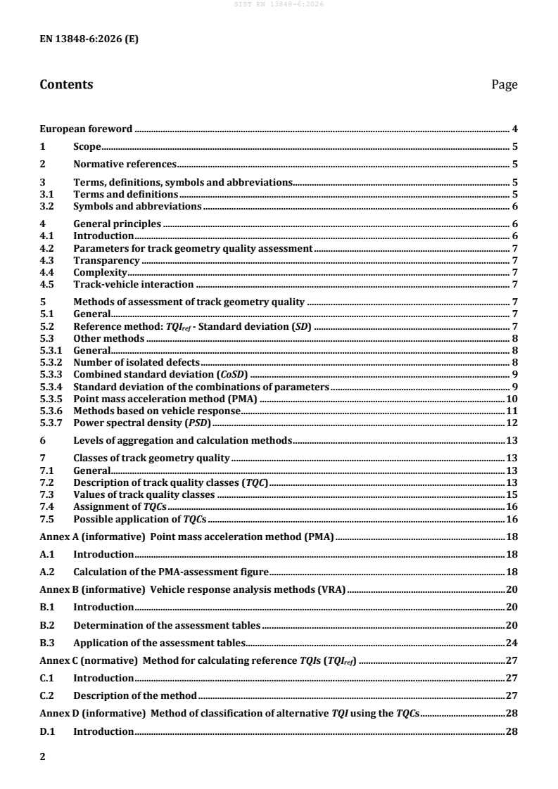
SIST EN 13848-6:2026 is the Slovenian adoption of EN 13848-6:2026 from CEN. It specifies how to characterise and classify track geometry quality using the parameters defined in EN 13848-1, and it defines track quality classes for railway track.
The standard is aimed at people who need a common way to describe track condition in practice, such as infrastructure managers, maintenance planners, quality managers, buyers, and vehicle designers. It helps them compare track sections, set quality classes, and relate measured geometry to operational use.
What does SIST EN 13848-6:2026 specify?
SIST EN 13848-6:2026 specifies a method to characterise and classify track geometry quality, and it sets out different track geometry classes. The document is organized into general principles, assessment methods, aggregation levels, and track quality classes, with four annexes that cover the main calculation and conversion methods.
The scope is limited to track geometry quality based on the parameters in EN 13848-1, and the document is not applied to lines with a nominal gauge below 1 435 mm or to urban rail systems.
| Annex | What it covers |
|---|---|
| Annex A | Point mass acceleration method (PMA) background and calculation |
| Annex B | Vehicle response analysis methods (VRA) and assessment tables |
| Annex C | Normative method for calculating reference TQIs |
| Annex D | Method for classifying alternative TQI using TQCs |
What are the key requirements of SIST EN 13848-6:2026?
Track geometry quality has to be assessed from EN 13848-1 parameters
SIST EN 13848-6:2026 requires assessment methods to be based on the track geometry parameters defined in EN 13848-1. In practice, this means the measured data has to come from the standard track geometry variables, not from ad hoc local indicators.
Clause 4 also sets three important principles: the assessment algorithm shall be fully documented, reproducible and available in the public domain; the number of TQIs should be kept as low as possible; and the method should reflect track-vehicle interaction. This matters because users need results they can explain, compare and defend in maintenance or acceptance decisions.
The reference method is SD of longitudinal level and alignment
Clause 5 makes standard deviation (SD) of longitudinal level and alignment the reference method for a Track Quality Index (TQI). Annex C gives the calculation method for the reference TQI (TQIref), so different networks can produce comparable results.
In practice, SD is calculated over 200 m, at every measuring step, and the track data are separated into speed classes. If the data come from chord measurements, they shall be decoloured to obtain the D1 domain. This matters because the same section can be assessed consistently across different measurement systems.
Other assessment methods are allowed if they are documented and traceable
Clause 5 also describes other ways to assess track geometry quality, including the number of isolated defects, Combined standard deviation (CoSD), standard deviation of parameter combinations, Point mass acceleration method (PMA), Vehicle response analysis (VRA), and Power spectral density (PSD). These are used where a network needs a method better aligned with its operational goals.
The practical point is that an alternative TQI can be used, but Annex D requires a documented relationship to the reference TQI and the TQCs. That is important when a network wants to keep its own method while still comparing results with the standard classes.
Levels of aggregation are tied to the intended decision
Clause 6 distinguishes detailed, intermediate, and overview levels of aggregation. Detailed level supports local intervention and short-term restrictions, intermediate level supports maintenance and renewal planning, and overview level supports strategic network decisions.
This matters because the same geometry data can serve different purposes. A short defect count may help with immediate maintenance, while SD over a longer section can support planning or network reporting.
Track quality classes are defined through speed and TQI ranges
Clause 7 defines five track quality classes, TQC A to E, with A being the best part of the distribution and E the worst part. The classes are based on the cumulative distribution of European track quality survey data and are given separately for longitudinal level and alignment.
The document uses these classes to classify track sections by speed range. Table 1 and Table 2 give the threshold values for each class, and Annex C is the required method when comparable classification is needed. For practical use, this means a section can be placed into a quality class for maintenance, contract, or vehicle-related decisions.
TQC assignment can be done in several ways
Clause 7.4 allows TQCs to be assigned using the maximum value, mean value, a percentile of the TQI distribution, or the percentage of a required TQC over a section. The standard links these approaches to the different aggregation levels.
In practice, this gives infrastructure managers flexibility: a strict worst-case view, an average view, or a coverage-based view can be chosen depending on whether the task is maintenance planning, contractual monitoring, or vehicle acceptance.
What terms does SIST EN 13848-6:2026 define?
- Track quality index (TQI) - A value that characterises track geometry quality for a track section based on parameters and methods in the EN 13848 series.
- Track quality class (TQC) - A class that expresses track geometry quality as a function of speed and as a range of TQIs.
- Decolouring - An algorithm that modifies spectral content to compensate for or apply the characteristics of a measuring system; in this series it converts chord measurements into D1 or D2 signals.
- Point mass acceleration (PMA) - A vehicle-independent assessment method that uses a virtual point mass guided over the track to derive a quality figure.
- Vehicle response analysis (VRA) - A method that estimates vehicle response from measured track geometry using models or assessment tables.
- Power spectral density (PSD) - A description of signal energy versus frequency for a given track geometry parameter and section.
- Combined standard deviation (CoSD) - A weighted combination of standard deviations of several geometry parameters into one assessment value.
Who uses SIST EN 13848-6:2026?
SIST EN 13848-6:2026 is used by infrastructure managers, railway undertakings, maintenance teams, and national authorities when they need to assess and summarise track geometry quality. It is also useful for vehicle manufacturers and designers who need to relate vehicle behaviour to track quality.
In practice, users apply it for maintenance strategy, working plans, acceptance of track works, contractual monitoring, vehicle design, and selection of track sections for vehicle acceptance.
What changed in SIST EN 13848-6:2026 from the previous edition?
SIST EN 13848-6:2026 supersedes SIST EN 13848-6:2014+A1:2021 and EN 13848-6:2014+A1:2020. The document states three significant technical changes: the structure has been changed, Annex A has been revised, and Annex B has been revised.
Which standards are used with SIST EN 13848-6:2026?
- EN 13848-1:2019 - Supplies the track geometry parameters and wavelength domains used for the assessment methods in this part.
- EN 17343 - Provides the general terms and definitions used in the document.
- EN 13848-5 - Is referenced for safety-related geometry limits and isolated defects, which are treated separately from the quality classification here.
- EN 14363 - Provides limit values and filtering context used in VRA methods and vehicle response assessment.
- EN 12299 - Is cited for measurement and evaluation of passenger ride comfort when vehicle response measurements are used.
- EN 13231-1 - Is cited for acceptance of works on ballasted track that can influence track geometry quality.
What does the SIST EN 13848-6:2026 document contain?
SIST EN 13848-6:2026 contains the reference SD method, several alternative assessment methods, aggregation guidance, and a class system for track geometry quality. It also includes formulas for SD, PMA and VRA-based assessment, plus tables that define class thresholds and the relative relevance of assignment methods.
Annex A and Annex B explain two model-based methods in more detail, with Annex B building assessment tables from simulated vehicle responses. Annex C gives the normative calculation steps for the reference TQI, and Annex D shows how an alternative TQI can be translated into the TQC framework.
Relations
- Effective Date
- 01-Sep-2026
- Effective Date
- 12-Aug-2026
- Effective Date
- 12-Aug-2026
- Effective Date
- 05-Aug-2026
- Effective Date
- 05-Aug-2026
- Effective Date
- 05-Aug-2026
- Effective Date
- 05-Aug-2026
- Effective Date
- 05-Aug-2026
- Effective Date
- 05-Aug-2026
Get Certified
Connect with accredited certification bodies for this standard

IRIS Certification (UNIFE)
International Railway Industry Standard certification.

TÜV SÜD Rail GmbH
TÜV SÜD railway certification services.

Bureau Veritas Railway Certification
Railway and transportation certification.
Sponsored listings
Frequently Asked Questions
SIST EN 13848-6:2026 is a standard published by the Slovenian Institute for Standardization (SIST). Its full title is "Railway applications - Track - Track geometry quality - Part 6: Characterisation of track geometry quality". This standard covers: This document specifies the method to characterize and classify the quality of track geometry based on parameters specified in EN 13848 1. This document also specifies different track geometry classes. This document does not: — apply to lines with a nominal gauge less than 1 435 mm; — specify requirements for urban rail systems.
This document specifies the method to characterize and classify the quality of track geometry based on parameters specified in EN 13848 1. This document also specifies different track geometry classes. This document does not: — apply to lines with a nominal gauge less than 1 435 mm; — specify requirements for urban rail systems.
SIST EN 13848-6:2026 is classified under the following ICS (International Classification for Standards) categories: 45.080 - Rails and railway components; 93.100 - Construction of railways. The ICS classification helps identify the subject area and facilitates finding related standards.
SIST EN 13848-6:2026 has the following relationships with other standards: It is inter standard links to SIST EN 13848-6:2014+A1:2021, SIST EN 13848-1:2019, SIST EN 17343:2023, SIST EN 13231-2:2006, SIST EN 13848-4:2025, SIST EN 13231-1:2006, SIST EN 13231-1:2024, SIST EN 16432-1:2017, SIST EN 13848-2:2021. Understanding these relationships helps ensure you are using the most current and applicable version of the standard.
SIST EN 13848-6:2026 is available in PDF format for immediate download after purchase. The document can be added to your cart and obtained through the secure checkout process. Digital delivery ensures instant access to the complete standard document.
Standards Content (Sample)
SLOVENSKI STANDARD
01-september-2026
Nadomešča:
SIST EN 13848-6:2014+A1:2021
Železniške naprave - Zgornji ustroj proge - Kakovost tirne geometrije - 6. del:
Karakterizacija kakovosti tirne geometrije
Railway applications - Track - Track geometry quality - Part 6: Characterisation of track
geometry quality
Bahnanwendungen - Oberbau - Gleislagequalität - Teil 6: Charakterisierung der
geometrischen Gleislagequalität
Applications ferroviaires - Voie - Qualité géométrique de la voie - Partie 6 :
Caractérisation de la qualité géométrique de la voie
Ta slovenski standard je istoveten z: EN 13848-6:2026
ICS:
45.080 Tračnice in železniški deli Rails and railway
components
93.100 Gradnja železnic Construction of railways
2003-01.Slovenski inštitut za standardizacijo. Razmnoževanje celote ali delov tega standarda ni dovoljeno.
EN 13848-6
EUROPEAN STANDARD
NORME EUROPÉENNE
July 2026
EUROPÄISCHE NORM
ICS 93.100 Supersedes EN 13848-6:2014+A1:2020
English Version
Railway applications - Track - Track geometry quality -
Part 6: Characterization of track geometry quality
Applications ferroviaires - Voie - Qualité géométrique Bahnanwendungen - Oberbau - Gleislagequalität - Teil
de la voie - Partie 6 : Caractérisation de la qualité 6: Charakterisierung der geometrischen
géométrique de la voie Gleislagequalität
This European Standard was approved by CEN on 27 April 2026.
CEN members are bound to comply with the CEN/CENELEC Internal Regulations which stipulate the conditions for giving this
European Standard the status of a national standard without any alteration. Up-to-date lists and bibliographical references
concerning such national standards may be obtained on application to the CEN-CENELEC Management Centre or to any CEN
member.
This European Standard exists in three official versions (English, French, German). A version in any other language made by
translation under the responsibility of a CEN member into its own language and notified to the CEN-CENELEC Management
Centre has the same status as the official versions.
CEN members are the national standards bodies of Austria, Belgium, Bulgaria, Croatia, Cyprus, Czech Republic, Denmark, Estonia,
Finland, France, Germany, Greece, Hungary, Iceland, Ireland, Italy, Latvia, Lithuania, Luxembourg, Malta, Netherlands, Norway,
Poland, Portugal, Republic of North Macedonia, Romania, Serbia, Slovakia, Slovenia, Spain, Sweden, Switzerland, Türkiye and
United Kingdom.
EUROPEAN COMMITTEE FOR STANDARDIZATION
COMITÉ EUROPÉEN DE NORMALISATION
EUROPÄISCHES KOMITEE FÜR NORMUNG
CEN-CENELEC Management Centre: Rue de la Science 23, B-1040 Brussels
© 2026 CEN All rights of exploitation in any form and by any means reserved Ref. No. EN 13848-6:2026 E
worldwide for CEN national Members.
Contents Page
European foreword . 4
1 Scope . 5
2 Normative references . 5
3 Terms, definitions, symbols and abbreviations. 5
3.1 Terms and definitions . 5
3.2 Symbols and abbreviations . 6
4 General principles . 6
4.1 Introduction . 6
4.2 Parameters for track geometry quality assessment . 7
4.3 Transparency . 7
4.4 Complexity . 7
4.5 Track-vehicle interaction . 7
5 Methods of assessment of track geometry quality . 7
5.1 General . 7
5.2 Reference method: TQI - Standard deviation (SD) . 7
ref
5.3 Other methods . 8
5.3.1 General . 8
5.3.2 Number of isolated defects . 8
5.3.3 Combined standard deviation (CoSD) . 9
5.3.4 Standard deviation of the combinations of parameters . 9
5.3.5 Point mass acceleration method (PMA) . 10
5.3.6 Methods based on vehicle response . 11
5.3.7 Power spectral density (PSD) . 12
6 Levels of aggregation and calculation methods . 13
7 Classes of track geometry quality . 13
7.1 General . 13
7.2 Description of track quality classes (TQC) . 13
7.3 Values of track quality classes . 15
7.4 Assignment of TQCs . 16
7.5 Possible application of TQCs . 16
Annex A (informative) Point mass acceleration method (PMA) . 18
A.1 Introduction . 18
A.2 Calculation of the PMA-assessment figure . 18
Annex B (informative) Vehicle response analysis methods (VRA) . 20
B.1 Introduction . 20
B.2 Determination of the assessment tables . 20
B.3 Application of the assessment tables . 24
Annex C (normative) Method for calculating reference TQIs (TQI ) . 27
ref
C.1 Introduction . 27
C.2 Description of the method . 27
Annex D (informative) Method of classification of alternative TQI using the TQCs . 28
D.1 Introduction . 28
D.2 Description of the conversion method . 28
Bibliography . 30
European foreword
This document (EN 13848-6:2026) has been prepared by Technical Committee CEN/TC 256 “Railway
applications”, the secretariat of which is held by DIN.
This European Standard shall be given the status of a national standard, either by publication of an identical
text or by endorsement, at the latest by January 2027, and conflicting national standards shall be withdrawn at
the latest by January 2027.
Attention is drawn to the possibility that some of the elements of this document may be the subject of patent
rights. CEN shall not be held responsible for identifying any or all such patent rights.
This document supersedes EN 13848-6:2014+A1:2020.
EN 13848-6:2014+A1:2020:
— change of the structure of the document;
— revision of Annex A;
— revision of Annex B.
In this document, the Annex C is normative and the Annexes A, B and D are informative.
The EN 13848 series, under the general title Railway applications — Track — Track geometry quality, consists
of the following parts:
— Part 1: Characterization of track geometry;
— Part 2: Measuring systems — Track recording vehicles;
— Part 3: Measuring systems — Track construction and maintenance machines;
— Part 4: Measuring systems — Manual and lightweight devices;
— Part 5: Geometric quality levels — Plain line, switches and crossings;
— Part 6: Characterization of track geometry quality.
Any feedback and questions on this document should be directed to the users’ national standards body. A
complete listing of these bodies can be found on the CEN website.
According to the CEN-CENELEC Internal Regulations, the national standards organisations of the following
countries are bound to implement this European Standard: Austria, Belgium, Bulgaria, Croatia, Cyprus, Czech
Republic, Denmark, Estonia, Finland, France, Germany, Greece, Hungary, Iceland, Ireland, Italy, Latvia,
Lithuania, Luxembourg, Malta, Netherlands, Norway, Poland, Portugal, Republic of North Macedonia, Romania,
Serbia, Slovakia, Slovenia, Spain, Sweden, Switzerland, Türkiye and the United Kingdom.
1 Scope
This document specifies the method to characterize and classify the quality of track geometry based on
parameters specified in EN 13848-1.
This document also specifies different track geometry classes.
This document does not:
— apply to lines with a nominal gauge less than 1 435 mm;
— specify requirements for urban rail systems.
2 Normative references
The following documents are referred to in the text in such a way that some or all of their content constitutes
requirements of this document. For dated references, only the edition cited applies. For undated references, the
latest edition of the referenced document (including any amendments) applies.
EN 13848-1:2019, Railway applications - Track - Track geometry quality - Part 1: Characterization of track
geometry
EN 17343, Railway applications - General terms and definitions
3 Terms, definitions, symbols and abbreviations
3.1 Terms and definitions
For the purposes of this document, the terms and definitions given in EN 17343 and the following apply.
ISO and IEC maintain terminology databases for use in standardization at the following addresses:
— ISO Online browsing platform: available at https://www.iso.org/obp/
— IEC Electropedia: available at https://www.electropedia.org/
3.1.1
decolouring
algorithm which modifies the spectral content of a signal aimed to compensate or apply the characteristics of a
specific measuring system
Note 1 to entry: The decolouring is used in EN 13848 series to convert a chord measurement signal into a D1 or D2
measurement signal.
3.1.2
track quality index
TQI
value that characterizes track geometry quality of a track section based on parameters and measuring methods
in conformity with the EN 13848 series
3.1.3
track quality class
TQC
characterization of track geometry quality as a function of speed and expressed as a range of TQIs
3.2 Symbols and abbreviations
For the purposes of this document, the following symbols and abbreviations apply:
AL alignment mm
ATQI alternative track quality index
CL cross level mm
CoSD combined standard deviation mm
cr curvature 1/m
D0 wavelength range 1 < λ ≤ 5 m
D1 wavelength range 3 < λ ≤ 25 m
D2 wavelength range 25 < λ ≤ 70 m
D3 wavelength range 70 < λ ≤ 150 for longitudinal level m
wavelength range 70 < λ ≤ 200 for alignment
λ wavelength m
G track gauge mm
LL longitudinal level mm
MBS multi body system
PMA point mass acceleration [method]
PSD power spectral density m /(1/m)
SD standard deviation mm
SD standard deviation, longitudinal level mm
LL
SD standard deviation, alignment mm
AL
TQI track quality index
TQIref reference track quality index
TQC track quality class
V speed km/h
VRA vehicle response analysis [method]
NOTE In this document, AL stands for “alignment” and is not to be confused with AL standing for “alert limit” as defined
in EN 13848-5.
4 General principles
4.1 Introduction
In order to provide a sufficient level of safety, ride quality and cost-effective railway traffic, track geometry
quality is assessed.
This document deals with track geometry quality classification regarding ride quality through TQIs. The safety
aspect on the other hand is covered in EN 13848-5.
TQIs can be calculated using different methods. The ones described in Clause 5 are applied by at least one
European network. The reference method for calculating comparable TQIs is detailed in Clause 7.
4.2 Parameters for track geometry quality assessment
As track geometry measurement systems present their outputs in accordance with the parameters specified in
EN 13848-1, any standardized assessment method shall be based on these parameters.
4.3 Transparency
Any algorithm for track geometry quality assessment complying with this document shall be fully documented,
reproducible and available in the public domain.
4.4 Complexity
Track geometry quality should be assessed by as few TQIs as possible and the algorithm should be
understandable by the user.
4.5 Track-vehicle interaction
Track quality assessment should reflect the principles of track-vehicle interaction. For example, the track
geometry defects of the same amplitude but different wavelengths lead to different vehicle responses and the
required wavelength range will be different depending on the track-vehicle interaction parameters to be
assessed.
5 Methods of assessment of track geometry quality
5.1 General
Considering their wide use across European railway networks and the need to have a single, easily
understandable TQI, standard deviation (SD) of longitudinal level and alignment defined in 5.2 is taken as the
reference method to describe track geometry quality. It will be referred to as TQI in the following and is
ref
specified in Annex C.
Establishing a TQI by other means may be used providing that complete documentation is available about the
method and how it relates to the reference method as described in Annex D.
The methods described in the following subclauses can be applied to any track geometry data of interest.
Switches may be included.
5.2 Reference method: TQI - Standard deviation (SD)
ref
The standard deviation is the most commonly used aggregation method to calculate TQI by European railway
networks. It represents the dispersion of a signal over a given track section, in relation to the mean value of this
signal over the considered section.
N
()xx−
∑
i
i=1
SD= (1)
N− 1
where
N is the number of values in the sample;
x is the current value of a signal;
i
x is the mean value of a signal;
SD is the standard deviation.
The standard deviation is linked to the energy of the signal in a given wavelength range [λ1, λ2] according to the
following relationship:
λ 2
SD = 2 S ()ννd (2)
xx
∫
λ1
where
S is the PSD described in 5.3.7 below.
xx
SD is commonly calculated for the following parameters:
— longitudinal level D1;
— alignment D1.
It is also calculated for other parameters such as:
— twist;
— track gauge;
— cross level;
— longitudinal level D2;
— alignment D2.
When calculating SD, attention should be paid to the possible influence of the quasi-static part (e.g. track design)
of the signals especially for twist, track gauge and cross level.
For longitudinal level and alignment it is recommended to calculate SD separately for each rail. It may also be
calculated differently (for example: mean of both rails, worst or best of either rail or outer rail in curves).
Length of track section used for standard deviation has influence on the result. If comparable results are
expected, only one length should be used. Commonly, for maintenance reasons standard deviation is calculated
over a length of 200 m. It may be calculated either at fixed distances without overlap or with overlap, as a sliding
standard deviation. Calculation of standard deviation is also done over longer distances such as 1 km, an entire
line or an entire network.
NOTE Distinction between specific track sections, such as plain lines, stations and switches and crossings, can also be
made.
5.3 Other methods
5.3.1 General
Other possible methods to calculate TQI used by some European railway networks are described in the
following subclauses.
5.3.2 Number of isolated defects
Isolated defects present a derailment risk; however counting the number of isolated defects exceeding a
specified threshold such as intervention limit and alert limit on a given fixed length of track can be
representative of the track geometry quality. This method is used by several European railway networks.
The number of isolated defects per unit of track length is commonly counted for the following parameters:
— longitudinal level D1;
— alignment D1;
— twist;
— track gauge;
— cross level.
It can also be counted for the following parameters:
— longitudinal level D2;
— alignment D2.
Commonly, the number of isolated defects is counted over 1 km of track or more. It may also be counted over
100 m or more according to the infrastructure manager. If required, distinction between specific track sections
can be made, such as plain lines, stations and switches and crossings.
Alternatively, a calculation can be made to specify what percentage of a line exceeds a certain threshold level.
5.3.3 Combined standard deviation (CoSD)
Assessment of the overall track geometry quality of a track section (200 m, 1 000 m.) can be done by a
combination of weighted standard deviations of individual geometric parameters. An example of such a TQI is
given below.
CoSD w SD ²+ w SD ²+ w SD ²+ w SD ² (3)
GG
AL AL CL CL LL LL
where
SD is the standard deviation of the geometry parameter x;
x
w is the weighting factor of the geometry parameter x;
x
with the indices
AL is the average of left and right alignments;
G is the track gauge;
CL is the cross level;
LL is the average of left and right longitudinal levels.
It is up to the infrastructure manager to determine the weighting factors according to the purpose of the
assessment.
Another method might be to transform the standard deviations of geometry parameters or their combinations
into a dimensionless number that can be used without distinction of line category, speed range and track
geometry parameter.
5.3.4 Standard deviation of the combinations of parameters
Standard deviation for a combination of track geometry parameters may be evaluated. This is based on the
observation that the level of the combined signals can better reflect the vehicle behaviour than the individual
signals.
For example, a standard deviation, over a sliding 200 m length of track, can be evaluated for the sum of
alignment and cross level filtered in the same wavelength range (e.g. D1) as follows:
— the alignments of left and right rails are combined into one signal y , in curves by choosing the outer rail
and on tangent track by either averaging or choosing one of the two rails;
— cross level and alignment signals are combined together to a signal, s, by using a sign convention so that an
alignment defect to the right is added with the same sign to a cross level defect where right rail is lower
than the left rail.
=
sy+∆z (4)
Figure 1 shows an example of the combination of cross level Δz and alignment y where the signs are both
positive;
— the standard deviation SD is calculated over a sliding 200 m length of track.
s
Key
1 reference position
ȳ combination of alignments
Δz cross level
X, Y, Z coordinate system
Figure 1 — Combination of alignment and cross level
5.3.5 Point mass acceleration method (PMA)
The PMA method is based on the following principles:
— The PMA model considers an unsprung virtual vehicle. It is assumed to be a point mass, thus only the motion
of the centre of gravity is investigated. This point mass is guided in a certain distance over the track centre
line.
— The point mass is moved at a constant speed corresponding to the maximum allowed speed over the
measured track section.
— Due to the geometrical imperfection of the track, which is described by the longitudinal level and alignment
of both rails, the point mass incurs accelerations a and a in the horizontal and vertical directions.
y z
— Summation of the magnitudes of the vectorial differences leads to an assessment value of track quality.
=
Features of PMA method are as follows:
— As the method is based on Newton’s second law, a PMA assessment value represents the accelerations
which are needed to guide a point mass.
— As the PMA model does not contain any vehicle specific features but the height of the centre of gravity, it
cannot show any vehicle specific reactions, and therefore it is considered to be a vehicle independent
assessment method.
— The PMA model takes into account the maximum line speed of the assessed track. To achieve the same PMA
track quality value a track with a high maximum line speed needs to have lower geometrical imperfection
than a track for a lower maximum line speed. In this way one single limit value may serve for possibly all
or at least a wide range of maximum line speeds.
— The derivatives of longitudinal level and alignment dominate the assessment value. Thus, defects of the
same amplitude but with different wavelengths lead to different assessment values.
— The PMA method combines vertical and lateral deviations as well as the left and right rails of the track.
Theoretical background information of the PMA method is given in Annex A.
5.3.6 Methods based on vehicle response
5.3.6.1 Estimation of vehicle response using a theoretical model
Vehicle response analysis (VRA) can be used to make objective, quantified statements about the relationship
between the track geometry quality and the vehicle’s responses at various speeds. It takes into consideration
factors such as successions of isolated defects that might generate resonance, combinations of defects at the
same location and local track design (e.g. curvature and cant).
The VRA methods are based on the following principles:
— calculation of vehicle response to the track geometry measured according to EN 13848-1, with the vehicle
response being represented by the wheel-rail forces and by accelerations of the vehicle running gear and
car body;
— consideration of different representative vehicle types, configurations and speeds;
— the assessment criteria takes into account the limit values given by EN 14363;
— the output can be linked to the input track geometry parameters.
When using such methods, attention should be paid to the consistency between the wavelength domain of the
track geometry and the frequency range of the vehicle response parameters.
Features of VRA methods are the following:
— VRA methods use the relationship between track geometry and vehicle behaviour to assess the track
geometry quality. By means of numerical models the method provides an estimation of vehicle response.
This response is compared to its respective limit values.
— VRA methods take into account the superposition of lateral and vertical track imperfections in combination
with the permissible vehicle speed and the resulting local cant deficiency.
— VRA methods do not require any definition of speed classes because the relevant limit values of the vehicle
responses are independent of the speed.
— In case of an exceedance of a defined limit value of vehicle response parameters, the limiting speed to be
applied can be determined.
— The assessment functions can be selected according to the relevant vehicle types which are authorized to
run on a considered track section.
An example of a VRA method is given in Annex B.
5.3.6.2 Measurement of vehicle response
Although not generally used for TQIs calculation, measurements of vehicle response can help in assessing
interaction between running vehicle and track, with respect to safety as well as ride quality.
Usually, the accelerations of bogie and car body are measured in both lateral and vertical directions, but
measurement of wheel-rail forces, such as lateral and vertical forces (Y and Q), can also be made.
In addition to the analysis method described in Annex E of EN 13848-1:2019, the assessment of accelerations
may be based on EN 14363 or EN 12299.
Inspection runs are usually made on high-speed lines, but they can also be of interest on conventional lines.
The following principles should be respected when using those measurements:
— The vehicles used for these evaluations are representative of the rolling stock used on the assessed lines.
— The runs are made at the maximum speed of the line, with a tolerance of ± 10 %.
— The measurements are made at the parts of the vehicle where the highest response is expected, e.g. the
leading bogie or wheelset.
— The state of the rail surface (wet or dry) is taken into account.
— The positio
...