

SIST EN 54-17:2006
(Main)Fire detection and fire alarm systems - Part 17: Short-circuit isolators
- Abstract
This European Standard specifies requirements, test methods and performance criteria for short-circuit isolators, for use in fire detection and fire alarm systems for buildings (see EN 54-1).
Means of isolation or protection incorporated within control and indicating equipment (Item B in Figure 1 of EN 54-1:1996) are not covered by this European Standard.
- Status
- Published
- Publication Date
- 31-Mar-2006
- Technical Committee
- POZ - Požarna varnost
- Current Stage
- 6060 - National Implementation/Publication (Adopted Project)
- Start Date
- 01-Apr-2006
- Due Date
- 01-Apr-2006
- Completion Date
- 01-Apr-2006
- Directive
- 2012-01-0929 - Odredba o določitvi standardov, ki so obvezni na področju zasebnega varovanja
305/2011 - Regulation (eu) No 305/2011 of the European Parliament and of the Council of 9 march 2011 laying down harmonised conditions for the marketing of construction products and repealing council directive 89/106/eecOJ Ref: C 259 OJ Date: 08-Aug-2014
89/106/EEC - Construction productsOJ Ref: C 304 OJ Date: 13-Dec-2006

SIST EN 54-17:2006 is the Slovenian adoption of EN 54-17:2005, published by SIST for short-circuit isolators used in fire detection and fire alarm systems for buildings. It specifies the requirements, test methods and performance criteria for devices that limit the effect of a short circuit so the rest of the transmission path can continue to operate.
What does SIST EN 54-17:2006 specify?
SIST EN 54-17:2006 covers short-circuit isolators for fire detection and fire alarm systems in buildings. It also makes clear that isolation or protection functions built into control and indicating equipment are outside its scope.
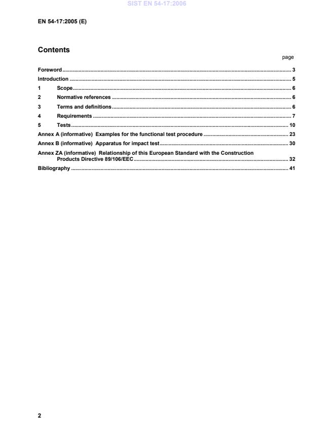
The document is organized into scope, normative references, terms and definitions, requirements, and tests. It also includes informative annexes with examples, test apparatus details, and the CE-marking relationship for construction products.
| Annex | What it covers |
|---|---|
| Annex A | Examples for the functional test procedure for different isolator concepts |
| Annex B | Apparatus for the impact test |
| Annex ZA | Relationship with the Construction Products Directive and CE marking information |
What are the key requirements of SIST EN 54-17:2006?
SIST EN 54-17:2006 requires a short-circuit isolator to be verified by inspection or engineering assessment and by the tests in Clause 5. In practice, that means the manufacturer must define the device well enough for it to be checked, then prove that it works under normal, environmental and EMC conditions.
Functional behavior and safety features
Clause 4 requires the isolator to have a normal closed condition that lets signals and supply current pass, and an open condition that blocks short-circuit currents. If the device has a visual status indication, that indication must not be red.
If the isolator connects to ancillary devices, such as remote indicators, failures in those connections must not stop the isolator from working. If the device is detachable from a mounting base, the system must be able to detect removal and signal a fault.
Settings, marking and data
Manufacturer settings must not be changeable except by special means or by breaking/removing a seal. On-site adjustment, where provided, is also restricted to a code or special tool, and every setting must still satisfy the standard.
Each isolator must be marked with the standard designation, manufacturer identification, model designation, terminal designations, and traceability information such as batch or serial identification and software version where relevant. The markings must stay visible for installation and maintenance.
The device must also be supplied with technical, installation and maintenance data. Clause 4.8 lists the key electrical parameters needed for testing and for correct application, including line voltage limits, current ratings, leakage current, impedance and the stimulus ranges that cause state changes. For a buyer or designer, this is the information needed to match the isolator to the loop design.
Software-controlled devices
If software is used to meet the requirements, Clause 4.9 adds documentation, design and storage rules. The software design must be modular, avoid invalid data causing errors, and avoid deadlock. The program and preset data must be protected in non-volatile memory, and writing to them must require special means.
Verification by test
Clause 5 requires a functional test and then a sequence of environmental and EMC tests. The test schedule includes reproducibility, supply voltage variation, dry heat, cold, humidity, corrosion, shock, impact, vibration, and EMC immunity. In practice, this shows whether the isolator still operates correctly after stresses it may see in service.
What terms does SIST EN 54-17:2006 define?
- Short-circuit isolator - A device in the transmission path that limits the effect of low parallel resistance faults between the lines.
- Closed condition - The state that allows normal signals and supply currents to pass through the isolator.
- Open condition - The state that prevents short-circuit currents from passing through the isolator.
- Vmax - The maximum line voltage stated by the manufacturer for the device.
- Vmin - The minimum line voltage stated by the manufacturer for the device.
- IC max - The maximum rated continuous current with the switch closed.
- IS max - The maximum rated switching current, including under short-circuit conditions.
- IL max - The maximum leakage current allowed in the open, isolated state.
- ZC max - The maximum series impedance allowed in the closed state.
Who uses SIST EN 54-17:2006?
SIST EN 54-17:2006 is used by manufacturers of fire detection and fire alarm components, test laboratories, notified product certification bodies, system designers, installers, and quality managers. It is especially relevant when selecting or certifying isolators for loop-based fire alarm systems in buildings. For users, the standard helps define what data to specify, how to test the device, and how to document conformity.
Which standards are used with SIST EN 54-17:2006?
The standard relies on EN 54-1:1996 for the general fire alarm system framework and terms. EN 50130-4:1995 provides the EMC immunity requirements used in Clause 5.
It also uses several EN 60068 environmental test standards for cold, dry heat, vibration, shock, damp heat and sulphur dioxide corrosion. ISO 209-1:1989 is used for the aluminium alloy specified for the impact test apparatus.
What does the SIST EN 54-17:2006 document contain?
The document gives a functional framework for short-circuit isolators, then sets out the requirements and test methods that prove the device still works under electrical, climatic, mechanical and EMC stresses. Clause 5 includes the test schedule and detailed procedures, while Annex A shows example functional test circuits and procedures for different isolator types.
Annex B describes the impact-test apparatus, including the hammer arrangement and dimensions. Annex ZA links the standard to CE marking, attestation of conformity, factory production control and the information that accompanies the product.
Relations
- Effective Date
- 09-Feb-2026
- Effective Date
- 09-Feb-2026
- Effective Date
- 09-Feb-2026
- Effective Date
- 09-Feb-2026
- Effective Date
- 09-Feb-2026
- Effective Date
- 09-Feb-2026
- Effective Date
- 09-Feb-2026
- Effective Date
- 28-Jan-2026
- Effective Date
- 28-Jan-2026
- Effective Date
- 28-Jan-2026
- Effective Date
- 22-Jul-2026
- Effective Date
- 08-Apr-2026
- Effective Date
- 09-Feb-2026
- Effective Date
- 09-Feb-2026
- Effective Date
- 28-Jan-2026
Get Certified
Connect with accredited certification bodies for this standard

CIS Institut d.o.o.
Personal Protective Equipment (PPE) certification body. Notified Body NB-2890 for EU Regulation 2016/425 PPE.

Kiwa BDA Testing
Building and construction product certification.
Kmetijski inštitut Slovenije
Agricultural Institute of Slovenia. Soil testing, plant health, agricultural product analysis.
Sponsored listings
Frequently Asked Questions
SIST EN 54-17:2006 is a standard published by the Slovenian Institute for Standardization (SIST). Its full title is "Fire detection and fire alarm systems - Part 17: Short-circuit isolators". This standard covers: This European Standard specifies requirements, test methods and performance criteria for short-circuit isolators, for use in fire detection and fire alarm systems for buildings (see EN 54-1). Means of isolation or protection incorporated within control and indicating equipment (Item B in Figure 1 of EN 54-1:1996) are not covered by this European Standard.
This European Standard specifies requirements, test methods and performance criteria for short-circuit isolators, for use in fire detection and fire alarm systems for buildings (see EN 54-1). Means of isolation or protection incorporated within control and indicating equipment (Item B in Figure 1 of EN 54-1:1996) are not covered by this European Standard.
SIST EN 54-17:2006 is classified under the following ICS (International Classification for Standards) categories: 13.220.20 - Fire protection; 13.320 - Alarm and warning systems. The ICS classification helps identify the subject area and facilitates finding related standards.
SIST EN 54-17:2006 has the following relationships with other standards: It is inter standard links to SIST EN IEC 60068-2-78:2025, SIST EN IEC 60068-2-1:2026, SIST EN 50130-4:1997, SIST EN 60068-1:2014, SIST EN 60068-2-42:2004, SIST EN IEC 60068-2-30:2025, SIST EN IEC 60068-2-2:2026, SIST EN 1365-1:1999, SIST EN 673:1999, SIST EN 54-1:1996, SIST EN 12845:2015+A2:2026, SIST EN 17229:2026, SIST EN 50600-2-5:2016, SIST EN 50600-2-5:2021, SIST EN 13565-2:2018. Understanding these relationships helps ensure you are using the most current and applicable version of the standard.
SIST EN 54-17:2006 is associated with the following European legislation: EU Directives/Regulations: 2012-01-0929, 2020-01-0063, 305/2011, 89/106/EEC, EUR-PUB; Standardization Mandates: M/109. When a standard is cited in the Official Journal of the European Union, products manufactured in conformity with it benefit from a presumption of conformity with the essential requirements of the corresponding EU directive or regulation.
SIST EN 54-17:2006 is available in PDF format for immediate download after purchase. The document can be added to your cart and obtained through the secure checkout process. Digital delivery ensures instant access to the complete standard document.
Standards Content (Sample)
2003-01.Slovenski inštitut za standardizacijo. Razmnoževanje celote ali delov tega standarda ni dovoljeno.ORþLOQLNLBrandmeldeanlagen - Teil 17: KurzschlussisolatorenSystemes de détection et d'alarme incendie - Partie 17: Isolateurs de court-circuitFire detection and fire alarm systems - Part 17: Short-circuit isolators13.320Alarmni in opozorilni sistemiAlarm and warning systems13.220.20Fire protectionICS:Ta slovenski standard je istoveten z:EN 54-17:2005SIST EN 54-17:2006en01-april-2006SIST EN 54-17:2006SLOVENSKI
STANDARD
EUROPEAN STANDARDNORME EUROPÉENNEEUROPÄISCHE NORMEN 54-17December 2005ICS 13.220.20 English VersionFire detection and fire alarm systems - Part 17: Short-circuitisolatorsSystèmes de détection et d'alarme incendie - Partie 17:Isolateurs de court-circuitBrandmeldeanlagen - Teil 17: KurzschlussisolatorenThis European Standard was approved by CEN on 26 October 2005.CEN members are bound to comply with the CEN/CENELEC Internal Regulations which stipulate the conditions for giving this EuropeanStandard the status of a national standard without any alteration. Up-to-date lists and bibliographical references concerning such nationalstandards may be obtained on application to the Central Secretariat or to any CEN member.This European Standard exists in three official versions (English, French, German). A version in any other language made by translationunder the responsibility of a CEN member into its own language and notified to the Central Secretariat has the same status as the officialversions.CEN members are the national standards bodies of Austria, Belgium, Cyprus, Czech Republic, Denmark, Estonia, Finland, France,Germany, Greece, Hungary, Iceland, Ireland, Italy, Latvia, Lithuania, Luxembourg, Malta, Netherlands, Norway, Poland, Portugal, Slovakia,Slovenia, Spain, Sweden, Switzerland and United Kingdom.EUROPEAN COMMITTEE FOR STANDARDIZATIONCOMITÉ EUROPÉEN DE NORMALISATIONEUROPÄISCHES KOMITEE FÜR NORMUNGManagement Centre: rue de Stassart, 36
B-1050 Brussels© 2005 CENAll rights of exploitation in any form and by any means reservedworldwide for CEN national Members.Ref. No. EN 54-17:2005: ESIST EN 54-17:2006
Examples for the functional test procedure.23 Annex B (informative)
Apparatus for impact test.30 Annex ZA (informative)
Relationship of this European Standard with the Construction Products Directive 89/106/EEC.32 Bibliography.41
1) To enable correct operation of the short-circuit isolators, these data should describe the requirements for the correct processing of the signals from the short-circuit isolator. This may be in the form of a full technical specification of these signals, a reference to the appropriate signalling protocol or a reference to suitable types of control and indicating equipment etc. SIST EN 54-17:2006
isolator; e) the way in which the modules are called, including any interrupt processing. f) a description of which areas of memory are used for the various purposes (e.g. the program, site specific data and running data); g) a designation, by which the software and its version can be uniquely identified. 4.9.2.2 The manufacturer shall have available detailed design documentation, which only needs to be provided if required by the testing authority. It shall comprise at least the following: a) an overview of the whole configuration of the device, including all software and hardware components; b) a description of each module of the program, containing at least: 1) the name of the module; 2) a description of the tasks performed; 3) a description of the interfaces, including the type of data transfer, the valid data range and the checking for valid data; SIST EN 54-17:2006
(15 to 35) °C; b) relative humidity: (25 to 75) %; c) air pressure:
(86 to 106) kPa. NOTE If variations in these parameters have a significant effect on a measurement, then such variations should be kept to a minimum during a series of measurements carried out as part of one test on one specimen. 5.1.2 Operating conditions for tests If a test method requires a specimen to be operational, then the specimen shall be connected to suitable supply and monitoring equipment with characteristics as required by the manufacturer's data. Unless otherwise specified in the test method, the supply parameters applied to the specimen shall be set within the manufacturer's specified range(s) and shall remain substantially constant throughout the SIST EN 54-17:2006
(IC max) or, if ZC can not be measured at IC max , because the isolator changes to the open condition before a current of IC max is reached, then it shall be measured just before the isolator changes to the open condition; f) the response to a direct short circuit applied to one side of the isolator. Examples of functional tests are given in Annex A. SIST EN 54-17:2006
5.2 Reproducibility 5.2.1 Object To show that each specimen meets the manufacturer’s specifications. 5.2.2 Test procedure The functional test described in 5.1.5 shall be conducted on each specimen. SIST EN 54-17:2006
Temperature: (+ 55 ± 2) °C
Duration: 16 h 5.4.2.4 Measurements during conditioning The specimen shall be monitored during the conditioning period to detect any change from the closed condition. During the last hour of the conditioning period, the functional test as described in 5.1.5 shall be conducted. SIST EN 54-17:2006
Temperature: (-10 ± 3) °C
Duration: 16 h 5.5.2.4 Measurements during conditioning The specimen shall be monitored during the conditioning period to detect any change from the closed condition. During the last hour of the conditioning period, the functional test as described in 5.1.5 shall be conducted. 5.5.2.5 Final measurements After a recovery period of at least 1 h at the standard laboratory conditions, the functional test as described in 5.1.5 shall be conducted. 5.5.3 Requirements The specimen shall remain in the closed condition during the conditioning period except when required to change during the functional test. SIST EN 54-17:2006
2 5.6.2.4 Measurements during conditioning The specimen shall be monitored during the conditioning period to detect any change from the closed condition. 5.6.2.5 Final measurements After the recovery period, the functional test as described in 5.1.5 shall be conducted. 5.6.3 Requirements The specimen shall remain in the closed condition during the conditioning period. The specimen shall function correctly within the manufacturer’s specification during the functional test. SIST EN 54-17:2006
Pulses per direction: 3
No test is applied to specimens with a mass >4,75 kg. 5.9.2.4 Measurements during conditioning The specimen shall be monitored during the conditioning period and for a further 2 min to detect any change from the closed condition. 5.9.2.5 Final measurements After the conditioning and the further 2 min, the functional test as described in 5.1.5 shall be conducted. 5.9.3 Requirements The specimen shall remain in the closed condition during the conditioning period and the additional 2 min. The specimen shall function correctly within the manufacturer’s specification during the functional test. 5.10 Impact (operational) 5.10.1 Object To demonstrate the immunity of the short-circuit isolator to mechanical impacts upon its surface, which it may sustain in the normal service environment, and which it can reasonably be expected to withstand. 5.10.2 Test procedure 5.10.2.1 Apparatus The test apparatus shall consist of a swinging hammer incorporating a rectangular-section aluminium alloy head (Aluminium alloy AlCu4SiMg complying with ISO 209-1, solution treated and precipitation treated condition) with the plane impact face chamfered to an angle of 60° to the horizontal, when in the striking position (i.e. when the hammer shaft is vertical). The hammer head shall be (50 ± 2,5) mm high, (76 ± 3,8) mm wide and (80 ± 4) mm long at mid height as shown in Figure B.1. A suitable apparatus is described in Annex B. 5.10.2.2 State of the specimen during conditioning The specimen shall be rigidly mounted to the apparatus by its normal mounting means and shall be positioned so that it is struck by the upper half of the impact face when the hammer is in the vertical position (i.e. when the hammerhead is moving horizontally). The azimuthal direction and position of impact, relative to the specimen shall be chosen as that most likely to impair the normal functioning of the specimen. The specimen shall be connected to its supply and monitoring equipment as described in 5.1.2. SIST EN 54-17:2006
Impact energy: (1,9 ± 0,1) J Hammer velocity: (1,5 ± 0,13) m s-1 Number of impacts: 1
5.10.2.4 Measurements during conditioning
The specimen shall be monitored during the conditioning period and for a further 2 min to detect any change from the closed condition. 5.10.2.5 Final measurements After the conditioning and the further 2 min, the functional test as described in 5.1.5 shall be conducted. 5.10.3 Requirements The specimen shall remain in the closed condition during the conditioning period and the additional 2 min. The specimen shall function correctly within the manufacturer’s specification during the functional test. 5.11 Vibration, sinusoidal (operational) 5.11.1 Object To demonstrate the immunity of the short-circuit isolator to vibration at levels considered appropriate to the normal service environment. 5.11.2 Test procedure 5.11.2.1 Reference The test apparatus and procedure shall be as described in EN 60068-2-6, Test Fc and as described below. 5.11.2.2 State of the specimen during conditioning The specimen shall be mounted on a rigid fixture as described in 5.1.3 and shall be connected to its supply and monitoring equipment as described in 5.1.2. The vibration shall be applied in each of three mutually perpendicular axes, in turn. The specimen shall be mounted so that one of the three axes is perpendicular to its normal mounting plane. SIST EN 54-17:2006
5.11.2.3 Conditioning The following conditioning shall be applied: Frequency range: (10 to 150) Hz Acceleration amplitude: 5 m s-2 (≈ 0,5 gn) Number of axes: 3 Sweep rate: 1 octave min-1 Number of sweep cycles: 1 per axis NOTE The vibration operational and endurance tests may be combined such that the specimen is subjected to the operational test conditioning followed by the endurance test conditioning in one axis before changing to the next axis. Only one final measurement need be made. 5.11.2.4 Measurements during conditioning The specimen shall be monitored during the conditioning period to detect any change from the closed condition. 5.11.2.5 Final measurements After the conditioning, the functional test as described in 5.1.5 shall be conducted. NOTE If the vibration operational and endurance tests are combined, the final measurements are made after the vibration endurance test and only need be made here if the operational test is conducted in isolation. 5.11.3 Requirements The specimen shall remain in the closed condition during the conditioning period. If the final measurement, as specified in 5.11.2.5, has been conducted, the specimen shall function correctly within the manufacturer’s specification during the functional test. 5.12 Vibration, sinusoidal (endurance) 5.12.1 Object To demonstrate the ability of the short-circuit isolator to withstand the long-term effects of vibration at levels appropriate to the service environment. 5.12.2 Test procedure 5.12.2.1 Reference The test apparatus and procedure shall be as described in EN 60068-2-6, Test Fc and as described below. SIST EN 54-17:2006
Sweep rate: 1 octave min-1 Number of sweep cycles: 20 per axis NOTE The vibration operational and endurance tests may be combined such that the specimen is subjected to the operational test conditioning followed by the endurance test conditioning in one axis before changing to the next axis. Only one final measurement need be made. 5.12.2.4 Final measurements After the conditioning, the functional test as described in 5.1.5 shall be conducted. 5.12.3 Requirements The specimen shall function correctly within the manufacturer’s specification during the functional test. 5.13 Electromagnetic Compatibility (EMC), Immunity tests (operational) 5.13.1 Object To demonstrate the immunity of the short-circuit isolator to electromagnetic interference. 5.13.2 Test procedure 5.13.2.1 Reference The test apparatus and procedure shall be as described in EN 50130-4 and as described below. 5.13.2.2 State of the specimen(s) during conditioning The specimen shall be mounted as described in 5.1.3 and shall be connected to supply and monitoring equipment as described in 5.1.2. SIST EN 54-17:2006
5.13.2.3 Conditioning The following EMC immunity tests shall be carried out, as described in EN 50130-4: a) electrostatic discharge; b) radiated electromagnetic fields; c) conducted disturbances induced by electromagnetic fields; d) fast transient bursts; e) slow high-energy voltage surges. 5.13.2.4 Measurements during conditioning During the conditioning the specimen shall be monitored to detect any change of state or faulty operation. 5.13.2.5 Final measurements After the conditioning, the functional test as described in 5.1.5 shall be conducted. 5.13.3 Requirements The specimen shall remain in the closed condition without any faulty operation during conditioning. The specimen shall function correctly within the manufacturer’s specification during the functional test.
Examples for the functional test procedure A.1 Introduction This annex gives some examples of functional test procedures for some hypothetical short-circuit isolators. For these examples the following simplistic and not necessarily practical types of isolators were envisaged: a) simple “autonomous” voltage sensing isolator. b) simple “autonomous” current sensing isolator. c) simple “controllable” isolator that can be instructed to open and close by the control and indicating equipment and will open if the voltage falls so low that the control and indicating equipment cannot command the device. For each example, a typical block diagram and list of the parameters, that need to be specified and verified is given. Examples of test circuits and test procedures for making the necessary tests and measurements are then given. A.2 Example 1: simple “autonomous” voltage sensing isolator VREFVREFa1a2b1b2 Figure A.1 — Typical block diagram for simple “autonomous” voltage sensing isolator A.2.1 Parameter specifications Vmax
The maximum line voltage; Vnom
The nominal line voltage; Vmin
The minimum line voltage; VSO max The maximum voltage at which the device isolates (i.e. switches from closed to open); VSO min The minimum voltage at which the device isolates (i.e. switches from closed to open); VSC max
The maximum voltage at which the device reconnects (i.e. switches from open to closed); VSC min
The minimum voltage at which the device reconnects (i.e. switches from open to closed). SIST EN 54-17:2006
The maximum rated continuous current with the switch closed; IS max
The maximum rated switching current (e.g. under short circuit conditions); IL max
The maximum leakage current with the switch open (isolated state); ZC max
The maximum series impedance with the switch closed. 12ISRIVinV1V2RFa1b1a2b2 Key 1 Power supply 2 Equipment under test (EUT) Figure A.2 — Test circuit for simple “autonomous” voltage sensing isolator A.2.2 Test procedure A.2.2.1 Connect the short-circuit isolator (EUT: equipment under test) to a test circuit as shown above with switch S open and RF set to infinity (i.e. an open circuit). A.2.2.2 Set Vin to the nominal line voltage, unless otherwise stated in a test procedure, and set the effective internal resistance of the supply RI to limit the short-circuit current to IS max
(i.e. RI = Vin / IS max). A.2.2.3 Apply an instantaneous short circuit by closing switch S. Measure the current I and record this as the leakage current IL. Check that IL ≤ IL max. A.2.2.4 Open switch S and monitor V2 to check that the device reconnects. A.2.2.5 Reduce RF until I = IC max. Then measure V1 and I and hence calculate the effective switch impedance ZC. Check that ZC ≤ ZC max. A.2.2.6 Increase RF to infinity (i.e. an open circuit) and adjust RI to (Vin – VSO min) / IC max. A.2.2.7 Reduce RF and measure the voltage V2 at the moment that the device isolates (i.e. the switch opens) and record this voltage as VSO. Check that VSO max ≥ VSO ≥ VSO min. A.2.2.8 Continue to reduce RF to zero and then measure the current I and record this as the leakage current IL. Check that IL ≤ IL max. SIST EN 54-17:2006
...