

ISO 23699
(Main)Microbeam analysis — Electron backscatter diffraction — Vocabulary
General Information
- Abstract
This document defines terms used for the electron backscatter diffraction (EBSD) technique. This document covers both general and specific concepts classified according to their hierarchy in a systematic order. This document is applicable to standardization documents relevant to EBSD practices. In addition, some definitions in this document are applicable to transmission Kikuchi diffraction (TKD).
- Status
- Not Published
- Technical Committee
- ISO/TC 202/SC 1 - Terminology
- Drafting Committee
- ISO/TC 202/SC 1 - Terminology
- Current Stage
- 6000 - International Standard under publication
- Start Date
- 11-Aug-2026
- Completion Date
- 26-Sep-2026
Buy Documents


ISO/FDIS 23699 - Microbeam analysis — Electron backscatter diffraction — Vocabulary


REDLINE ISO/FDIS 23699 - Microbeam analysis — Electron backscatter diffraction — Vocabulary
Overview
ISO 23699: Microbeam analysis - Electron backscatter diffraction - Vocabulary is an international standard developed by ISO technical committee ISO/TC 202/SC 1. This standard defines terminology used in electron backscatter diffraction (EBSD) and related microbeam analysis techniques. By providing a common vocabulary, ISO 23699 supports professionals in scientific and engineering communities who use EBSD for materials characterization.
EBSD is a powerful microstructural analysis tool commonly used in conjunction with scanning electron microscopy (SEM). It enables researchers and industry experts to analyze the crystallographic structure, orientation, phase, and texture of materials at high spatial resolution.
Key Topics
ISO 23699 systematically organizes definitions into key areas:
Physical Basis of EBSD
- Terminology related to crystallography (crystal, unit cell, planes, directions, orientation)
- Concepts such as symmetry, point groups, and misorientation
- EBSD-specific physics, including electron diffraction and Kikuchi patterns
EBSD Instrumentation and Hardware
- EBSD detectors and phosphor screens
- Forescatter detectors (FSD) and pixelated sensors
- Parameters like detector distance and working distance
Operation and Data Acquisition
- Background correction and binning
- Indexing processes and hit rates
- Pattern quality, misindexing, and phase identification
- Step size and exposure time
Data Display and Analysis
- EBSD mapping, pixels, and analysis of grains and grain boundaries
- Tools for measuring crystal orientation (Euler angles, pole figures, inverse pole figures)
- Distribution functions and kernel-based misorientation metrics (KAM, LAM)
- Reliability indices and methods for data cleaning
Applications
The vocabulary standardized in ISO 23699 is essential for:
- Materials Science and Engineering: Facilitates communication and reproducibility in research on metals, ceramics, semiconductors, and geological materials.
- Industrial Quality Control: Assists in the evaluation of microstructures in aerospace, automotive, nuclear, and electronics sectors, ensuring product reliability and performance.
- Academic Research: Enables precise reporting and understanding of EBSD data in scholarly publications.
- Software and Equipment Development: Provides harmonized terminology for vendors producing EBSD systems or analysis software.
Typical EBSD applications include:
- Mapping grain orientation and texture in alloys and composites
- Investigating phase distribution in polycrystalline samples
- Characterizing grain boundary features and misorientations
- Supporting failure analysis by revealing microstructural defects
Related Standards
ISO 23699 complements several other international standards relevant to microbeam analysis and electron diffraction techniques, such as:
- ISO 23703:2022 - Microbeam analysis - EBSD - Measurement and reporting of crystallographic orientation
- ISO 24173:2024 - Microbeam analysis - Vocabulary for electron diffraction techniques
- ISO 13067:2020 - Microbeam analysis - Guidelines for EBSD
- Additional references: Online platforms such as the ISO Online Browsing Platform and IEC Electropedia maintain up-to-date terminology databases.
Implementing ISO 23699 in your laboratory, research, or industrial practice helps ensure clear communication, consistency, and high-quality EBSD measurements. For further information, consult the official ISO website or your national standards body.
Buy Documents
ISO/FDIS 23699 - Microbeam analysis — Electron backscatter diffraction — Vocabulary
REDLINE ISO/FDIS 23699 - Microbeam analysis — Electron backscatter diffraction — Vocabulary
Get Certified
Connect with accredited certification bodies for this standard

ECOCERT
Organic and sustainability certification.

Eurofins Food Testing Global
Global leader in food, environment, and pharmaceutical product testing.

Intertek Bangladesh
Intertek certification and testing services in Bangladesh.
Sponsored listings
Frequently Asked Questions
ISO 23699 is a draft published by the International Organization for Standardization (ISO). Its full title is "Microbeam analysis — Electron backscatter diffraction — Vocabulary". This standard covers: This document defines terms used for the electron backscatter diffraction (EBSD) technique. This document covers both general and specific concepts classified according to their hierarchy in a systematic order. This document is applicable to standardization documents relevant to EBSD practices. In addition, some definitions in this document are applicable to transmission Kikuchi diffraction (TKD).
This document defines terms used for the electron backscatter diffraction (EBSD) technique. This document covers both general and specific concepts classified according to their hierarchy in a systematic order. This document is applicable to standardization documents relevant to EBSD practices. In addition, some definitions in this document are applicable to transmission Kikuchi diffraction (TKD).
ISO 23699 is classified under the following ICS (International Classification for Standards) categories: 01.040.71 - Chemical technology (Vocabularies); 71.040.50 - Physicochemical methods of analysis. The ICS classification helps identify the subject area and facilitates finding related standards.
ISO 23699 is available in PDF format for immediate download after purchase. The document can be added to your cart and obtained through the secure checkout process. Digital delivery ensures instant access to the complete standard document.
Standards Content (Sample)
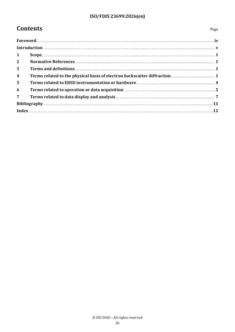
FINAL DRAFT
International
Standard
ISO/FDIS 23699
ISO/TC 202/SC 1
Microbeam analysis — Electron
Secretariat: UNBS
backscatter diffraction —
Voting begins on:
Vocabulary
2026-06-15
Voting terminates on:
2026-08-10
RECIPIENTS OF THIS DRAFT ARE INVITED TO SUBMIT,
WITH THEIR COMMENTS, NOTIFICATION OF ANY
RELEVANT PATENT RIGHTS OF WHICH THEY ARE AWARE
AND TO PROVIDE SUPPOR TING DOCUMENTATION.
IN ADDITION TO THEIR EVALUATION AS
BEING ACCEPTABLE FOR INDUSTRIAL, TECHNO
LOGICAL, COMMERCIAL AND USER PURPOSES, DRAFT
INTERNATIONAL STANDARDS MAY ON OCCASION HAVE
TO BE CONSIDERED IN THE LIGHT OF THEIR POTENTIAL
TO BECOME STAN DARDS TO WHICH REFERENCE MAY BE
MADE IN NATIONAL REGULATIONS.
Reference number
ISO/FDIS 23699:2026(en) © ISO 2026
FINAL DRAFT
ISO/FDIS 23699:2026(en)
International
Standard
ISO/FDIS 23699
ISO/TC 202/SC 1
Microbeam analysis — Electron
Secretariat: UNBS
backscatter diffraction —
Voting begins on:
Vocabulary
Voting terminates on:
RECIPIENTS OF THIS DRAFT ARE INVITED TO SUBMIT,
WITH THEIR COMMENTS, NOTIFICATION OF ANY
RELEVANT PATENT RIGHTS OF WHICH THEY ARE AWARE
AND TO PROVIDE SUPPOR TING DOCUMENTATION.
© ISO 2026
IN ADDITION TO THEIR EVALUATION AS
All rights reserved. Unless otherwise specified, or required in the context of its implementation, no part of this publication may
BEING ACCEPTABLE FOR INDUSTRIAL, TECHNO
LOGICAL, COMMERCIAL AND USER PURPOSES, DRAFT
be reproduced or utilized otherwise in any form or by any means, electronic or mechanical, including photocopying, or posting on
INTERNATIONAL STANDARDS MAY ON OCCASION HAVE
the internet or an intranet, without prior written permission. Permission can be requested from either ISO at the address below
TO BE CONSIDERED IN THE LIGHT OF THEIR POTENTIAL
or ISO’s member body in the country of the requester.
TO BECOME STAN DARDS TO WHICH REFERENCE MAY BE
MADE IN NATIONAL REGULATIONS.
ISO copyright office
CP 401 • Ch. de Blandonnet 8
CH-1214 Vernier, Geneva
Phone: +41 22 749 01 11
Email: copyright@iso.org
Website: www.iso.org
Published in Switzerland Reference number
ISO/FDIS 23699:2026(en) © ISO 2026
ii
ISO/FDIS 23699:2026(en)
Contents Page
Foreword .iv
Introduction .v
1 Scope . 1
2 Normative References . 1
3 Terms and definitions . 1
4 Terms related to the physical basis of electron backscatter diffraction. 1
5 Terms related to EBSD instrumentation or hardware . 4
6 Terms related to operation or data acquisition . 5
7 Terms related to data display and analysis . 7
Bibliography .11
Index .12
iii
ISO/FDIS 23699:2026(en)
Foreword
ISO (the International Organization for Standardization) is a worldwide federation of national standards
bodies (ISO member bodies). The work of preparing International Standards is normally carried out through
ISO technical committees. Each member body interested in a subject for which a technical committee
has been established has the right to be represented on that committee. International organizations,
governmental and non-governmental, in liaison with ISO, also take part in the work. ISO collaborates closely
with the International Electrotechnical Commission (IEC) on all matters of electrotechnical standardization.
The procedures used to develop this document and those intended for its further maintenance are described
in the ISO/IEC Directives, Part 1. In particular, the different approval criteria needed for the different types
of ISO document should be noted. This document was drafted in accordance with the editorial rules of the
ISO/IEC Directives, Part 2 (see www.iso.org/directives).
ISO draws attention to the possibility that the implementation of this document may involve the use of (a)
patent(s). ISO takes no position concerning the evidence, validity or applicability of any claimed patent
rights in respect thereof. As of the date of publication of this document, ISO had not received notice of (a)
patent(s) which may be required to implement this document. However, implementers are cautioned that
this may not represent the latest information, which may be obtained from the patent database available at
www.iso.org/patents. ISO shall not be held responsible for identifying any or all such patent rights.
Any trade name used in this document is information given for the convenience of users and does not
constitute an endorsement.
For an explanation of the voluntary nature of standards, the meaning of ISO specific terms and expressions
related to conformity assessment, as well as information about ISO's adherence to the World Trade
Organization (WTO) principles in the Technical Barriers to Trade (TBT), see www.iso.org/iso/foreword.html.
This document was prepared by Technical Committee ISO/TC202, Microbeam analysis, Subcommittee SC1,
Terminology.
Any feedback or questions on this document should be directed to the user’s national standards body. A
complete listing of these bodies can be found at www.iso.org/members.html.
iv
ISO/FDIS 23699:2026(en)
Introduction
Electron backscatter diffraction (EBSD) measurement is routinely and widely used to produce local
orientation maps of a polished surface of bulk materials in scanning electron microscopy (SEM), via the
automated recording and analysis of Kikuchi diffraction patterns. EBSD is a modern technique used to
evaluate phase distribution, grain size distribution, orientation of individual grains, disorientation inside
grains and grain boundary characteristics of the crystalline materials. EBSD is applied across a wide variety
of fields, such as in metals processing, aerospace, nuclear, automotive and microelectronics industries, and
earth sciences.
This document provides definitions of terms as they are used in the field of electron backscatter diffraction
by the international scientific and engineering communities that employ the technique.
v
FINAL DRAFT International Standard ISO/FDIS 23699:2026(en)
Microbeam analysis — Electron backscatter diffraction —
Vocabulary
1 Scope
This document defines terms used for the electron backscatter diffraction (EBSD) technique. This document
covers both general and specific concepts classified according to their hierarchy in a systematic order.
This document is applicable to standardization documents relevant to EBSD practices. In addition, some
definitions in this document are applicable to transmission Kikuchi diffraction (TKD).
2 Normative References
There are no normative references in this document.
3 Terms and definitions
ISO and IEC maintain terminology databases for use in standardization at the following addresses:
— ISO Online browsing platform: available at https:// www .iso .org/ obp
— IEC Electropedia: available at https:// www .electropedia .org/
4 Terms related to the physical basis of electron backscatter diffraction
4.1
crystal
crystal structure
entity consisting of a regular, repeated arrangement of atoms in space
Note 1 to entry: It is usually described by a space group, a crystal system, unit cell parameters (including the lengths
and angles between the unit cell axes) and the positions of the atoms inside the unit cell
[SOURCE: ISO 24173:2024, 3.1, modified — the second half of the definition has been moved to "Note 1 to
entry", and all original "Note" clauses removed.]
4.2
crystal unit cell
cell which is repeated (infinitely) to build up the crystal (4.1)
Note 1 to entry: It is usually defined by three lengths, a, b, c, and three angles, α, β, γ. The lengths are usually given in
nanometres and the angles in degrees.
4.3
crystal plane
plane, usually denoted as (hkl) or (hkil), that represents the intersection of a plane with the a-, b-, and c-axes
of the unit cell at distances of 1/h, 1/k, 1/l, where h, k, and l are integers, i=-(h+k)
Note 1 to entry: The integers h, k, and l are usually referred to as Miller indices of a crystal plane.
[SOURCE: ISO 24173:2024, 3.2, modified — “or (hkil)” and “i=-(h+k)” are added, “representing” are replaced
with “that represents”, “the minimum mutual” are removed. ]
ISO/FDIS 23699:2026(en)
4.4
crystal direction
direction, usually denoted as [uvw] or [uvtw], that represents a vector direction in multiples of the basis
vectors describing the a, b, and c crystal axes, where u, v, and w are integers, t=-(u+v)
[SOURCE: ISO 24173:2024, 3.3, modified — “or [uvtw]” and “where u, v, and w are integers, t=-(u+v)” are
added, “representing” is replaced with “that represents”. ]
4.5
crystallographic orientation
alignment of the crystal coordinate system (for example, [100], [010], [001] for a cubic crystal) in relation to
the specimen coordinate system
Note 1 to entry: The specimen coordinate system can be denoted as X, Y, Z. When EBSD (4.9) is applied to the study of
rolled materials, it is often denoted as RD, TD, ND (RD = reference (or rolling) direction, TD = transverse direction and
ND = normal direction).
[SOURCE: ISO 24173:2024, 3.4]
4.6
Laue class
eleven geometric crystal classes containing centrosymmetric crystallographic types of point groups (4.7)
and their subgroups
4.7
point group
group of symmetry (4.19) operations which maps a point lattice onto itself
Note 1 to entry: In three dimensions, the symmetry (4.19) operations of these groups are restricted to 1, 2, 3, 4, 6 and
-1, -2, -3, -4, -6, m, respectively.
4.8
dynamical diffraction
theory of diffuse inelastic scattering in which the electron is treated as a wave field which is scattered
multiple times by interaction with the periodic potential of the atoms in the crystal (4.1)
Note 1 to entry: Models based on dynamical diffraction theory are used to simulate EBSPs (4.10).
4.9
electron backscatter diffraction
EBSD
diffraction process that arises between the backscattered electrons and the atomic planes of a highly tilted
crystalline specimen when illuminated by a stationary incident electron beam
[SOURCE: ISO 23703:2022, 3.4]
4.10
electron backscatter diffraction pattern
EBSP
Kikuchi-pattern-like electron diffraction pattern which is generated on a phosphor screen (5.3), photographic
film or direct electron detector by backscatter diffracted electrons in a SEM
Note 1 to entry: A specimen is generally tilted to 70 degrees to get better quality of the diffraction pattern.
[SOURCE: ISO 23703:2022, 3.5, modified— “EBSD pattern” has been changed to “EBSP” and “or direct
electron detector” are added.]
4.11
Hough transform
mathematical transformation of image processing techniques, which converts a line in an image to a point
Note 1 to entry: This allows automated detection of bands in an EBSP (4.10).
ISO/FDIS 23699:2026(en)
Note 2 to entry: In EBSD (4.9), a linear Hough transform is used to identify the position and orientation (4.15) of the
Kikuchi bands in each EBSP (4.10), which enables the EBSP (4.10) to be indexed. Each Kikuchi band is identified as a
bright spot in Hough space. The Hough transform is essentially a special case of the Radon transform. Generally, the
Hough transform is for binary images, and the Radon transform is for grey-level images.
[SOURCE: ISO 23703:2022, 3.9]
4.12
Kikuchi diffraction
simple elastic approximation for dynamical diffraction (4.8)
[1]
Note 1 to entry: Proposed in 1928 by Seishi Kikuchi .
4.13
microtexture
population of crystallographic orientations (4.15) whose individual components are linked to their spatial
[2]
location within the microstructure
4.14
misorientation
difference in the alignment of the coordinate systems of two crystals with the same crystal structure (4.1),
which can be expressed as an angle/axis pair
Note 1 to entry: Misorientation is the rotation required to bring one crystal (4.1) into coincidence with another. It can
be described by a rotation matrix, a set of Euler angles (7.7), an axis/angle pair or a Rodrigues vector. The axis/angle
pair is most common, but the smallest angle description is generally used.
Note 2 to entry: The EBSD (4.9) software calculates the crystal orientation of a particular point on the specimen
surface based on the EBSP (4.10) acquired at that point. The software can then calculate the misorientation between
any two chosen pairs or groups of orientations (4.15) of the same crystal phase acquisition points.
[SOURCE: ISO 24173:2024, 3.14, modified — “in the orientation of two crystallites, usually” has been changed
to “in the alignment of the coordinate systems of two crystals with the same crystal structure, which can
be”]
4.15
orientation
mathematical description of the angular relationship between the crystal axes of the analysis point and a
reference frame, usually the specimen axes
[SOURCE: ISO 13067:2020, 3.1.3]
4.16
pseudosymmetry
potential for an EBSP (4.10) to be indexed in several different ways due to internal similarities within the
EBSP (4.10)
Note 1 to entry: Pseudosymmetry is a problem with some crystal orientations (4.15), usually when a main zone axis
is in the centre of the pattern. Typical cases are a {0001} pole for a hexagonal structure and a <111> pole for a cubic
structure.
Note 2 to entry: Structures such as high-symmetry tetragonal crystals with an axial ratio, c/a, approximately equal to
1 are also likely to exhibit pseudosymmetry in EBSPs (4.10).
Note 3 to entry: Pseudosymmetry effects can usually be minimized by decreasing the specimen-to-screen distance, in
order to capture more Kikuchi bands, and by using more bands for indexing (6.7).
[SOURCE: ISO 13067:2020, 3.1.9, modified — “EBSD pattern” are changed to “EBSP” and “Note 3 to entry” is
added]
ISO/FDIS 23699:2026(en)
4.17
transmission Kikuchi diffraction
TKD
diffraction process that arises between the dynamically diffracted electrons and the bottom atomic planes
of an electron transparent crystalline specimen illuminated by a stationary incident electron beam which
[3]
usually uses high energy (25 keV to 30 keV) incident electrons
Note 1 to entry: Commonly used alternative terms for TKD are “t-EBSD”.
Note 2 to entry: On-axis TKD is a variant of TKD. It uses a modified EBSD detector (5.1) inserted below the electron
transparent sample. This sample-detector geometry is very similar to that used in a TEM.
4.18
EBSD spatial resolution
minimum distance between two grains (7.9) (separated by a sharp boundary) that can produce two distinctly
different EBSPs (4.10), which can be correctly indexed using a specific indexing (6.7) method
Note 1 to entry: The physical spatial resolution of EBSD (4.9) is not related to the indexing (6.7) of the EBSD patterns,
but rather to the volume of material that generates the EBSD pattern.
Note 2 to entry: The effective spatial resolution of EBSD (4.9) is typically finer than the physical spatial resolution. It
is determined by the ability of the analysis software to discriminate between overlapping patterns, which often occur
near the boundary between two neighbouring grains (7.9).
4.19
symmetry
property an object is said to have if it looks the same when rotated, translated or mirrored in a certain way
[SOURCE: ISO 24173:2024, 3.20]
4.20
zone axis
point in an EBSP (4.10) where the centres of several Kikuchi bands intersect
Note 1 to entry: It corresponds to a low-index crystal direction (4.4) in the EBSP (4.10).
[SOURCE: ISO 24173:2024, 3.21]
4.21
phase
physically homogeneous volume in a material having the same structure and chemical composition
[SOURCE: ISO 13067:2020, 3.2.8]
5 Terms related to EBSD instrumentation or hardware
5.1
EBSD detector
detector used to capture the electron backscatter pattern and convert it to an image visible on the display
device (computer sc
...
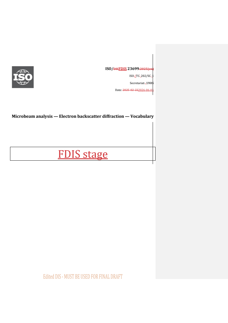
ISO/DISFDIS 23699:2025(en)
ISO /TC 202/SC 1
Secretariat: UNBS
Date: 2025-02-222026-06-01
Microbeam analysis — Electron backscatter diffraction — Vocabulary
FDIS stage
ISO /FDIS 23699-CD:####(X:2026(en)
All rights reserved. Unless otherwise specified, or required in the context of its implementation, no part of this publication
may be reproduced or utilized otherwise in any form or by any means, electronic or mechanical, including photocopying,
or posting on the internet or an intranet, without prior written permission. Permission can be requested from either ISO
at the address below or ISO'sISO’s member body in the country of the requester.
ISO copyright office
Case postale 56 • CP 401 • Ch. de Blandonnet 8
CH-12111214 Vernier, Geneva 20
Tel.Phone: + 41 22 749 01 11
Fax + 41 22 749 09 47
E-mail: copyright@iso.org
Webwww.iso.org
Website: www.iso.org
Published in Switzerland.
ii © ISO #### 2026 – All rights reserved
ii
ISO/DISFDIS 23699:20252026(en)
Contents
Foreword . iv
Introduction . v
1 Scope . 1
2 Normative References . 1
3 Terms and definitions . 1
4 Terms related to the physical basis of electron backscatter diffraction . 1
5 Terms related to EBSD instrumentation or hardware . 5
6 Terms related to operation or data acquisition . 5
7 Terms related to data display and analysis . 8
Bibliography . 13
Index 14
iii
ISO /FDIS 23699-CD:####(X:2026(en)
Foreword
ISO (the International Organization for Standardization) is a worldwide federation of national standards
bodies (ISO member bodies). The work of preparing International Standards is normally carried out through
ISO technical committees. Each member body interested in a subject for which a technical committee has been
established has the right to be represented on that committee. International organizations, governmental and
non-governmental, in liaison with ISO, also take part in the work. ISO collaborates closely with the
International Electrotechnical Commission (IEC) on all matters of electrotechnical standardization.
The procedures used to develop this document and those intended for its further maintenance are described
in the ISO/IEC Directives, Part 1. In particular, the different approval criteria needed for the different types of
ISO document should be noted. This document was drafted in accordance with the editorial rules of the
ISO/IEC Directives, Part 2 (see www.iso.org/directives).
ISO draws attention to the possibility that the implementation of this document may involve the use of (a)
patent(s). ISO takes no position concerning the evidence, validity or applicability of any claimed patent rights
in respect thereof. As of the date of publication of this document, ISO had not received notice of (a) patent(s)
which may be required to implement this document. However, implementers are cautioned that this may not
represent the latest information, which may be obtained from the patent database available at
www.iso.org/patents.www.iso.org/patents. ISO shall not be held responsible for identifying any or all such
patent rights.
Any trade name used in this document is information given for the convenience of users and does not
constitute an endorsement.
For an explanation of the voluntary nature of standards, the meaning of ISO specific terms and expressions
related to conformity assessment, as well as information about ISO's adherence to the World Trade
Organization (WTO) principles in the Technical Barriers to Trade (TBT), see
www.iso.org/iso/foreword.htmlwww.iso.org/iso/foreword.html.
This document was prepared by Technical Committee ISO/TC202, Microbeam analysis, Subcommittee SC1,
Terminology.
Any feedback or questions on this document should be directed to the user’s national standards body. A
complete listing of these bodies can be found at www.iso.org/members.html.
Field Code Changed
iv © ISO #### 2026 – All rights reserved
iv
ISO/DISFDIS 23699:20252026(en)
Introduction
Electron backscatter diffraction (EBSD) measurement is routinely and widely used to produce local
orientation maps of a polished surface of bulk materials in scanning electron microscopy (SEM), via the
automated recording and analysis of Kikuchi diffraction patterns. EBSD is a modern technique used to evaluate
phase distribution, grain size distribution, orientation of individual grains, disorientation inside grains and
grain boundary characteristics of the crystalline materials. EBSD is applied across a wide variety of fields, such
as in metals processing, aerospace, nuclear, automotive and microelectronics industries, and earth sciences
etc.
This document provides definitions of terms as they are used in the field of electron backscatter diffraction by
the international scientific and engineering communities that employ the technique.
v
DRAFT International Standard ISO/DIS 23699:2025(en)
Microbeam analysis — Electron backscatter diffraction — Vocabulary
1 Scope
This document defines terms used for the electron backscatter diffraction (EBSD) technique. This document
covers both general and specific concepts classified according to their hierarchy in a systematic order.
This document is applicable to all standardization documents relevant to theEBSD practices of EBSD. In
addition, some definitions in this document are applicable to transmission Kikuchi diffraction (TKD).
2 Normative References
There are no normative references in this document.
3 Terms and definitions
ISO and IEC maintain terminology databases for use in standardization at the following addresses:
— — ISO Online browsing platform: available at https://www.iso.org/obphttps://www.iso.org/obp
— — IEC Electropedia: available at https://www.electropedia.org/https://www.electropedia.org/
4 Terms related to the physical basis of electron backscatter diffraction
4.1 4.1
crystal
crystal structure
entity consisting of a regular, repeated arrangement of atoms in space
Note 1 to entry: It is usually described by a space group, a crystal system, unit cell parameters (including the lengths
and angles between the unit cell axes) and the positions of the atoms inside the unit cell
[SOURCE: ISO 24173:2024, 3.1, modified — the second half of the sentencedefinition has been changedmoved
to "Note 1 to entry 1", and all original "Note" clauses removed. ].]
4.2 4.2
crystal unit cell
cell which is repeated (infinitely) to build up the crystal (4.1)(Error! Reference source not found.)
Note 1 to entry: It is usually defined by three lengths, a, b, c, and three angles, α, β, γ. The lengths are usually given in
nanometres and the angles in degrees.
4.3 4.3
crystal plane
plane, usually denoted as (hkl) or (hkil), that represents the intersection of a plane with the a-, b-, and c-axes
of the unit cell at distances of 1/h, 1/k, 1/l, where h, k, and l are integers, i=-(h+k)
Note 1 to entry: The integers h, k, and l are usually referred to as Miller indices of a crystal plane.
ISO /FDIS 23699-CD:####(X:2026(en)
[SOURCE: ISO 24173:2024, 3.2, modified — “or (hkil)” and “i=-(h+k)” are added, “representing” are replaced
with “that represents”, “the minimum mutual” are removed. ]
4.4 4.4
crystal direction
direction, usually denoted as [uvw] or [uvtw], that represents a vector direction in multiples of the basis
vectors describing the a, b, and c crystal axes, where u, v, and w are integers, t=-(u+v)
[SOURCE: ISO 24173:2024, 3.3, modified — “or [uvtw]” and “where u, v, and w are integers, t=-(u+v)” are
added, “reprenting” arerepresenting” is replaced with “that represents”. ]
4.5 4.5
crystallographic orientation
alignment of the crystal coordinate system (for example, [100], [010], [001] for a cubic crystal) in relation to
the specimen coordinate system
Note 1 to entry: The specimen coordinate system can be denoted as X, Y, Z. When EBSD (4.9)(Error! Reference source
not found.) is applied to the study of rolled materials, it is often denoted as RD, TD, ND (RD = reference (or rolling)
direction, TD = transverse direction and ND = normal direction).
[SOURCE: ISO 24173:2024, 3.4]
4.6 4.6
Laue class
eleven geometric crystal classes containing centrosymmetric crystallographic types of point groups
(4.7)(Error! Reference source not found.) and their subgroups
4.7 4.7
point group
group of symmetry (4.19)(Error! Reference source not found.) operations which maps a point lattice onto
itself
Note 1 to entry: In three dimensions, the symmetry (4.19)(Error! Reference source not found.) operations of these
groups are restricted to 1, 2, 3, 4, 6 and -1, -2, -3, -4, -6, m, respectively.
4.8 4.8
dynamical diffraction
theory of diffuse inelastic scattering in which the electron is treated as a wave field which is scattered multiple
times by interaction with the periodic potential of the atoms in the crystal (4.1)(Error! Reference source not
found.)
Note 1 to entry: Models based on dynamical diffraction theory are used to simulate EBSPs (4.10).(Error! Reference
source not found.).
4.9 4.9
electron backscatter diffraction
EBSD
diffraction process that arises between the backscattered electrons and the atomic planes of a highly tilted
crystalline specimen when illuminated by a stationary incident electron beam
[SOURCE: ISO 23703:2022, 3.4]
2 © ISO #### 2026 – All rights reserved
ISO/DISFDIS 23699:20252026(en)
4.10 4.10
electron backscatter diffraction pattern
EBSP
Kikuchi-pattern-like electron diffraction pattern which is generated on a phosphor screen (5.3),(Error!
Reference source not found.), photographic film or direct electron detector by backscatter diffracted
electrons in a SEM
Note 1 to entry: A specimen is generally tilted to 70 degrees to get better quality of the diffraction pattern.
[SOURCE: ISO 23703:2022, 3.5, modified— “EBSD pattern” has been changed to “EBSP” and “or direct electron
detector” are added.]
4.11 4.11
Hough transform
mathematical transformation of image processing techniques, which converts a line in an image to a point
Note 1 to entry: This allows automated detection of bands in an EBSP (4.10).(Error! Reference source not found.).
Note 2 to entry: In EBSD (4.9),(Error! Reference source not found.), a linear Hough transform is used to identify the
position and orientation (4.15)(Error! Reference source not found.) of the Kikuchi bands in each EBSP (4.10),(Error!
Reference source not found.), which enables the EBSP (4.10)(Error! Reference source not found.) to be indexed. Each
Kikuchi band is identified as a bright spot in Hough space. The Hough transform is essentially a special case of the Radon
transform. Generally, the Hough transform is for binary images, and the Radon transform is for grey-level images.
[SOURCE: ISO 23703:2022, 3.9]
4.12 4.12
Kikuchi diffraction
simple elastic approximation for dynamical diffraction (4.8) (Error! Reference source not found.)
[1]
Note 1 to entry: Proposed in 1928 by Seishi Kikuchi. [1].
4.13 4.13
microtexture
population of crystallographic orientations (4.15)(Error! Reference source not found.) whose individual
[2]
components are linked to their spatial location within the microstructure [2]
4.14 4.14
misorientation
difference in the alignment of the coordinate systems of two crystals with the same crystal structure
(4.1),(Error! Reference source not found.), which can be expressed as an angle/axis pair
Note 1 to entry: Misorientation is the rotation required to bring one crystal (4.1)(Error! Reference source not found.)
into coincidence with another. It can be described by a rotation matrix, a set of Euler angles (7.7),(Error! Reference
source not found.), an axis/angle pair or a Rodrigues vector. The axis/angle pair is most common, but the smallest angle
description is generally used.
Note 2 to entry: The EBSD (4.9)(Error! Reference source not found.) software calculates the crystal orientation of a
particular point on the specimen surface based on the EBSP (4.10)(Error! Reference source not found.) acquired at
that point. The software can then calculate the misorientation between any two chosen pairs or groups of orientations
(4.15)(Error! Reference source not found.) of the same crystal phase acquisition points.
[SOURCE: ISO 24173:2024, 3.14, modified — “in the orientation of two crystallites, usually” has been changed
to “in the alignment of the coordinate systems of two crystals with the same crystal structure, which can be”]
ISO /FDIS 23699-CD:####(X:2026(en)
4.15 4.15
orientation
mathematical description of the angular relationship between the crystal axes of the analysis point and a
reference frame, usually the specimen axes
[SOURCE: ISO 13067:2020, 3.1.3]
4.16 4.16
pseudosymmetry
potential for an EBSP (4.10)(Error! Reference source not found.) to be indexed in several different ways
due to internal similarities within the EBSP (4.10)(Error! Reference source not found.)
Note 1 to entry: Pseudosymmetry is a problem with some crystal orientations (4.15),(Error! Reference source not
found.), usually when a main zone axis is in the centre of the pattern. Typical cases are a {0001} pole for a hexagonal
structure and a <111> pole for a cubic structure.
Note 2 to entry: Structures such as high-symmetry tetragonal crystals with an axial ratio, c/a, approximately equal to 1
are also likely to exhibit pseudosymmetry in EBSPs (4.10).(Error! Reference source not found.).
Note 3 to entry: Pseudosymmetry effects can usually be minimized by decreasing the specimen-to-screen distance, in
order to capture more Kikuchi bands, and by using more bands for indexing (6.7).(Error! Reference source not found.).
[SOURCE: ISO 13067:2020, 3.1.9, modified — “EBSD pattern” are changed to “EBSP” and “Note 3 to entry” is
added]
4.17 4.17
transmission Kikuchi diffraction
TKD
diffraction process that arises between the dynamically diffracted electrons and the bottom atomic planes of
an electron transparent crystalline specimen when illuminated by a stationary incident electron beam which
[3]
usually uses high energy (25 keV- to 30 keV) incident electrons [3]
Note 1 to entry: Commonly used alternative terms for TKD are “t-EBSD”.
Note 2 to entry: On-axis TKD is a variant of TKD. It uses a modified EBSD detector (5.1)(Error! Reference source not
found.) inserted below the electron transparent sample. This sample-detector geometry is very similar to that used in a
TEM.
4.18 4.18
EBSD spatial resolution
minimum distance between two grains (7.9)(Error! Reference source not found.) (separated by a sharp
boundary) that can produce two distinctly different EBSPs (4.10),(Error! Reference source not found.),
which can be correctly indexed using a specific indexing (6.7)(Error! Reference source not found.) method
Note 1 to entry: The physical spatial resolution of EBSD (4.9)(Error! Reference source not found.) is not related to
the indexing (6.7)(Error! Reference source not found.) of the EBSD patterns, but rather to the volume of material that
generates the EBSD pattern.
Note 2 to entry: The effective spatial resolution of EBSD (4.9)(Error! Reference source not found.) is typically finer
than the physical spatial resolution. It is determined by the ability of the analysis software to discriminate between
overlapping patterns, which often occur near the boundary between two neighbouring grains (7.9).(Error! Reference
source not found.).
4.19 4.19
symmetry
property an object is said to have if it looks the same when rotated, translated or mirrored in a certain way
4 © ISO #### 2026 – All rights reserved
ISO/DISFDIS 23699:20252026(en)
[SOURCE: ISO 24173:2024, 3.20]
4.20 4.20
zone axis
point in an EBSP (4.10)(Error! Reference source not found.) where the centres of several Kikuchi bands
intersect
Note 1 to entry: It corresponds to a low-index crystal direction (4.4)(Error! Reference source not found.) in the EBSP
(4.10).(Error! Reference source not found.).
[SOURCE: ISO 24173:2024, 3.21]
4.21 4.21
phase
physically homogeneous volume in a material having the same structure and chemical composition
[SOURCE: ISO 13067:2020, 3.2.8]
5 Terms related to EBSD instrumentation or hardware
5.1 5.1
EBSD detector
detector used to capture the electron backscatter pattern and convert it to an image visible on the display
device (computer screen) via a video-camera
Note 1 to entry: Commonly, a high-sensitivity charged-coupled device (CCD), or complementary metal-oxide-
semiconductors (CMOS) is used.
[SOURCE: ISO 24173:2024, 3. 5]
5.2 5.2
forescatter detector
FSD
electron detector which provides an analog signal from a sample in the EBSD (4.9)(Error! Reference source
not found.) geometry whose intensity contains both background and diffraction signal from a single location
on the sample
5.3 5.3
phosphor screen
screen used to convert the electron signal to a visible light signal which can be detected with a low-light-level
camera
Note 1 to entry: For some devices, it is directly coupled to the camera sensor with a fibre optical bundle.
[SOURCE: ISO 24173:2024, 3. 17, modified — the content of “Note 1 to entry” is changed.]
5.4 5.4
pixelated sensor
active-pixel sensor
sensor that directly coverts an incoming electron into an electric signal
Note 1 to entry: Unlike phosphor screens (5.3),(Error! Reference source not found.), the direct conversion of
incoming electrons to an electric signal avoids to conversion into light.
ISO /FDIS 23699-CD:####(X:2026(en)
6 Terms related to operation or data acquisition
6.1 6.1
background correction
procedure to remove the non-linear background intensity from the EBSP (4.10)(Error! Reference source not
found.) to increase the uniformity of the pattern illumination and produce a clearer EBSP (4.10)(Error!
Reference source not found.)
Note 1 to entry: Set A background pattern can be generated by setting the electron beam to a low intensity and
scanscanning the sample in a random or patterned manner, this will generate a background pattern, which willcan be
used to correct the EBSPs (4.10)(Error! Reference source not found.) obtained from the sample.
Note 2 to entry: The background can be removed by an image-division flat-fielding technique
...