

ISO 14907-1
(Main)Electronic fee collection — Test procedures for user and fixed equipment — Part 1: Description of test procedures
- Abstract
This document specifies the test procedures of electronic fee collection (EFC) roadside equipment (RSE) and on-board equipment (OBE) with regard to the conformance to standards and requirements for type approval and acceptance testing which is within the realm of EFC application specifically. The scope of this document is restricted to systems operating within the radio emission, electromagnetic compatibility (EMC) regulations, traffic, and other regulations of the countries in which they are operated. This document identifies a set of suitable parameters and provides test procedures to enable the proof of a complete EFC system, as well as components of an EFC system, e.g. OBE, related to the defined requirements of an application. The defined parameter and tests are assigned to the following groups of parameters: — functionality; — quality; — referenced pre-tests. An overview of the tests and parameters provided by this document is given in 5.1 and 5.2. This document describes procedures, methods and tools, and a test plan which shows the relation between all tests and the sequence of these tests. It lists all tests that are required to measure the performance of EFC equipment. It describes which EFC equipment is covered by the test procedures; the values of the parameters to be tested are not included. It also describes how the tests are to be performed and which tools and prerequisites are necessary before this series of tests can be undertaken. It is assumed that the security of the system is inherent in the communications and EFC functionality tests, therefore they are not addressed here. All tests in this document provide instructions to evaluate the test results. This document defines only the tests and test procedures, not the benchmark figures that these are to be measured against. The test procedures defined in this document can be used as input, e.g. by scheme owners, for prototype testing, type approvals, tests of installations and periodic inspections. Related to a conceptual model of an EFC system, this document relates only to the equipment of the user and the service provider. Any other entities are outside the scope of document. EFC systems for dedicated short-range communication (DSRC) consist, in principle, of a group of technical components, which in combination fulfil the functions required for the collection of fees by electronic automatic means. These components comprise all, or most, of the following: — OBE within a vehicle; — OBE containing the communications and computing sub-functions; — optional integrated circuit card which may carry electronic money, service rights, and other secured information; — communication between OBE and RSE based on DSRC; — equipment for the fee collection at the RSE containing the communications and computing sub-functions; — equipment for the enforcement at the roadside; — central equipment for the administration and operation of the system. The scope of this document relates solely to OBE and RSE and the DSRC interface between OBE and RSE including its functions to perform the fee collection. All the equipment used for enforcement (e.g. detection, classification, localization, and registration) and central equipment are outside the scope of this document.
- Status
- Not Published
- Technical Committee
- ISO/TC 204 - Intelligent transport systems
- Drafting Committee
- ISO/TC 204/WG 5 - Fee and toll collection
- Current Stage
- 6000 - International Standard under publication
- Start Date
- 05-Sep-2026
- Completion Date
- 10-Oct-2026
Buy Documents

ISO/PRF 14907-1 - Electronic fee collection — Test procedures for user and fixed equipment — Part 1: Description of test procedures
REDLINE ISO/PRF 14907-1 - Electronic fee collection — Test procedures for user and fixed equipment — Part 1: Description of test procedures
ISO 14907-1 is an ISO document for electronic fee collection (EFC) test procedures for roadside equipment (RSE) and on-board equipment (OBE). It defines how to test DSRC-based EFC equipment for type approval and acceptance testing, for the benefit of manufacturers, operators, test houses, and certification bodies.
The standard sets out the test parameters, test methods, test plan structure, evaluation, and certification approach. It gives procedures and references for the tests, but not the benchmark figures the equipment is measured against.
What does ISO 14907-1 specify?
ISO 14907-1 specifies test procedures for EFC RSE and OBE, with the scope limited to systems operating under the radio emission, electromagnetic compatibility (EMC), traffic, and other regulations that apply where they are used. The document is focused on automated EFC using standardized dedicated short-range communication (DSRC), and it is limited to the user equipment and service provider equipment that take part in fee collection.
It covers the DSRC interface between OBE and RSE and the functions needed to perform fee collection. Enforcement equipment and central system equipment are outside the scope, as are manual payment methods and other non-DSRC payment forms.
The document is organized into these main clauses and annexes:
| Annex | What it covers |
|---|---|
| Annex A | Guidance on how to use the document |
| Annex B | Traffic, vehicle, and other performance tests |
| Annex C | Reliability and availability tests |
| Annex D | Classes of equipment |
| Annex E | Examples of statistical calculations |
| Annex F | Examples of referenced pre-tests based on European test procedures |
| Annex G | Test methods and tools |
| Annex H | Examples of EFC scenarios |
| Annex I | Examples of referenced pre-tests based on Japanese test procedures |
Clause 5 gives the test parameter overview, test plan, and required documentation. Clause 6 lists the inspections and tests, and Clause 7 covers evaluation and certification.
What are the key requirements of ISO 14907-1?
ISO 14907-1 requires an individual test plan for each EFC system or component under type approval or acceptance testing. That matters in practice because the document is meant to be adapted to the exact application, the equipment under test, and the operating environment.
Test planning and documentation
Clause 5.3 says the test plan shall identify the test parameter and item, the related requirement or severity, the selected test type, the required tools and environment, the department carrying out the test, and the required documentation of the tests and results. In practical terms, the plan is the record that connects each parameter to a defined test method and to the evidence that will support approval or acceptance.
Clause 5.4 requires the manufacturer to supply documentation before testing can proceed. The listed items include the system description, system specification, safety and security concept, user documentation, ambient conditions, operational directives, quality assurance directives, maintenance and installation directives, and the manufacturer’s available design and production documents. This means the test house is not working from the equipment alone, but from the technical information needed to judge it correctly.
Test groups and how they are selected
Clause 5.2 groups the parameters into referenced pre-tests, functionality tests, and quality tests. The tables also mark each test as basic or conditional - basic means highly recommended, while conditional means it is only performed when the feature is relevant to the system under evaluation. In practice, that lets operators and test houses focus effort on the functions and environments that matter for the intended deployment.
The same tables indicate test categories with “p” and “o” markers. A “p” test is expected to be performed for conformity to the document, while an “o” test is optional. That helps a test house build a plan that is strict where needed and selective where the system design allows it.
Referenced pre-tests
Clause 6.1 covers referenced pre-tests for DSRC, environmental conditions, and EMC. These tests refer to existing standards or technical specifications rather than redefining the underlying methods here. For the reader, that means the document points to established radio, environmental, and EMC procedures that must already be satisfied before the EFC-specific tests continue.
Functionality tests
Clause 6.2 covers communication, the EFC application, traffic conditions, vehicle characteristics, and environmental influences. The parameter overview in Tables 1 to 3 includes conditions such as vehicle speed, lane changing, shadowing, windscreen effects, antenna mounting height, pavement width, number of lanes, weather, and other influences.
This matters because EFC performance depends on the real traffic scene, not only on a bench setup. The document therefore asks the tester to consider vehicle geometry, lane arrangement, and environmental conditions that can affect the DSRC communication zone and transaction performance.
Quality tests
Clause 6.3 covers quality management and reliability and availability. The quality management part points to ISO 9000-related quality management material and ISO 9001 compliance requirements. The reliability and availability part includes component, equipment, system, transaction-level reliability, OBE life duration, OBE battery duration, and OBE smart card life duration.
In practice, this section links EFC testing to how the equipment is designed, produced, installed, serviced, and kept operating over time. It is not only about whether a transaction works once, but whether the equipment can keep working at the required level.
Evaluation and certification
Clause 7 says test houses or test laboratories that evaluate EFC components or systems shall comply with ISO/IEC 17025. Certification bodies shall comply with ISO/IEC 17065. The evaluation is based on type approval and/or acceptance test results, and the test report and certificate have specified content requirements.
That means the standard is not only a test list - it also defines the competence framework for the organizations doing the evaluation and certification, and the information that must appear in the report trail.
What terms does ISO 14907-1 define?
- decision - A conclusion, based on review, that says whether fulfilment of specified requirements has or has not been demonstrated.
- review - Consideration of whether the selection and determination activities, and their results, are suitable and effective for showing that requirements are met.
- EFC equipment - Equipment comprising roadside equipment (RSE) and on-board equipment (OBE).
- test status - The nature of a test, either basic or conditional.
- DSRC - Dedicated short-range communication, the communication basis used by the document for EFC transactions.
- OBE - On-board equipment in the vehicle that participates in the fee collection process.
- RSE - Roadside equipment that interacts with the OBE at the roadside.
- SUT - System under test, the EFC item being evaluated.
Who uses ISO 14907-1?
ISO 14907-1 is used by manufacturers, operators, test houses, certification bodies, and scheme owners working with EFC systems. It is relevant where EFC is used for toll collection, road pricing, parking, and individual traffic information, including applications linked to the European Electronic Toll Service (EETS).
Manufacturers use it for prototype testing, factory testing, and preparing equipment for approval. Operators use it to define a test programme for the intended application and to compare equipment from different suppliers. Test houses and certification bodies use it as the common basis for assessments, reports, and certificates.
What changed in ISO 14907-1 from the previous edition?
ISO 14907-1:2026 is the second edition and it cancels and replaces ISO 14907-1:2020. The stated changes are:
- the test groups are presented in a sequence that reflects pre-tests, functionality tests, and quality tests
- the terms and definitions are updated
- ISO 17573-2 is included as the primary source for harmonized EFC terminology
- the references have been revised
Which standards are used with ISO 14907-1?
| Standard | What it contributes |
|---|---|
| ISO/IEC 17025:2017 | Competence requirements for testing and calibration laboratories, used for evaluation activities |
| ISO/IEC 17065:2012 | Requirements for product certification bodies, used for certification activities |
| ISO 17573-2 | Vocabulary for vehicle-related tolling, used as the terminology source |
| ISO 14906 | Application interface definition for DSRC, used in the transaction-level reliability discussion |
| ISO 14907-2 | Conformance test for the OBU application interface, cited as a companion part in the series |
| ISO 37444 | Charging performance framework for EFC, mentioned as a related reference in the introduction |
What does the ISO 14907-1 document contain?
ISO 14907-1 contains a parameter overview in Tables 1 to 3, with the tests grouped as referenced pre-tests, functionality tests, and quality tests. It also contains a test plan structure and a documentation list that a manufacturer must provide before testing.
Annex B gives detailed traffic, vehicle, and environmental test examples, including lane changing, shadowing, windscreen effects, antenna mounting, pavement width, and weather conditions. Annex C gives reliability and availability methods, including transaction-level reliability and OBE lifetime-related examples, while Annex E provides statistical calculation examples for sample size and confidence.
Annex F and Annex I show example referenced pre-tests based on European and Japanese procedures, and Annex G describes inspection, simulation, laboratory, and field test methods plus a sample test protocol form. Annex H gives example EFC scenarios for single vehicles and bulk vehicles, which helps the reader map the test parameters to realistic traffic situations.
Relations
- Effective Date
- 26-Sep-2026
- Effective Date
- 12-Feb-2026
- Consolidates
ISO 11666:2018 - Non-destructive testing of welds — Ultrasonic testing — Acceptance levels - Effective Date
- 30-Aug-2025
- Effective Date
- 26-Jul-2025
Buy Documents
ISO/PRF 14907-1 - Electronic fee collection — Test procedures for user and fixed equipment — Part 1: Description of test procedures
REDLINE ISO/PRF 14907-1 - Electronic fee collection — Test procedures for user and fixed equipment — Part 1: Description of test procedures
Get Certified
Connect with accredited certification bodies for this standard

BSI Group
BSI (British Standards Institution) is the business standards company that helps organizations make excellence a habit.

TÜV Rheinland
TÜV Rheinland is a leading international provider of technical services.

TÜV SÜD
TÜV SÜD is a trusted partner of choice for safety, security and sustainability solutions.
Sponsored listings
Frequently Asked Questions
ISO 14907-1 is a draft published by the International Organization for Standardization (ISO). Its full title is "Electronic fee collection — Test procedures for user and fixed equipment — Part 1: Description of test procedures". This standard covers: This document specifies the test procedures of electronic fee collection (EFC) roadside equipment (RSE) and on-board equipment (OBE) with regard to the conformance to standards and requirements for type approval and acceptance testing which is within the realm of EFC application specifically. The scope of this document is restricted to systems operating within the radio emission, electromagnetic compatibility (EMC) regulations, traffic, and other regulations of the countries in which they are operated. This document identifies a set of suitable parameters and provides test procedures to enable the proof of a complete EFC system, as well as components of an EFC system, e.g. OBE, related to the defined requirements of an application. The defined parameter and tests are assigned to the following groups of parameters: — functionality; — quality; — referenced pre-tests. An overview of the tests and parameters provided by this document is given in 5.1 and 5.2. This document describes procedures, methods and tools, and a test plan which shows the relation between all tests and the sequence of these tests. It lists all tests that are required to measure the performance of EFC equipment. It describes which EFC equipment is covered by the test procedures; the values of the parameters to be tested are not included. It also describes how the tests are to be performed and which tools and prerequisites are necessary before this series of tests can be undertaken. It is assumed that the security of the system is inherent in the communications and EFC functionality tests, therefore they are not addressed here. All tests in this document provide instructions to evaluate the test results. This document defines only the tests and test procedures, not the benchmark figures that these are to be measured against. The test procedures defined in this document can be used as input, e.g. by scheme owners, for prototype testing, type approvals, tests of installations and periodic inspections. Related to a conceptual model of an EFC system, this document relates only to the equipment of the user and the service provider. Any other entities are outside the scope of document. EFC systems for dedicated short-range communication (DSRC) consist, in principle, of a group of technical components, which in combination fulfil the functions required for the collection of fees by electronic automatic means. These components comprise all, or most, of the following: — OBE within a vehicle; — OBE containing the communications and computing sub-functions; — optional integrated circuit card which may carry electronic money, service rights, and other secured information; — communication between OBE and RSE based on DSRC; — equipment for the fee collection at the RSE containing the communications and computing sub-functions; — equipment for the enforcement at the roadside; — central equipment for the administration and operation of the system. The scope of this document relates solely to OBE and RSE and the DSRC interface between OBE and RSE including its functions to perform the fee collection. All the equipment used for enforcement (e.g. detection, classification, localization, and registration) and central equipment are outside the scope of this document.
This document specifies the test procedures of electronic fee collection (EFC) roadside equipment (RSE) and on-board equipment (OBE) with regard to the conformance to standards and requirements for type approval and acceptance testing which is within the realm of EFC application specifically. The scope of this document is restricted to systems operating within the radio emission, electromagnetic compatibility (EMC) regulations, traffic, and other regulations of the countries in which they are operated. This document identifies a set of suitable parameters and provides test procedures to enable the proof of a complete EFC system, as well as components of an EFC system, e.g. OBE, related to the defined requirements of an application. The defined parameter and tests are assigned to the following groups of parameters: — functionality; — quality; — referenced pre-tests. An overview of the tests and parameters provided by this document is given in 5.1 and 5.2. This document describes procedures, methods and tools, and a test plan which shows the relation between all tests and the sequence of these tests. It lists all tests that are required to measure the performance of EFC equipment. It describes which EFC equipment is covered by the test procedures; the values of the parameters to be tested are not included. It also describes how the tests are to be performed and which tools and prerequisites are necessary before this series of tests can be undertaken. It is assumed that the security of the system is inherent in the communications and EFC functionality tests, therefore they are not addressed here. All tests in this document provide instructions to evaluate the test results. This document defines only the tests and test procedures, not the benchmark figures that these are to be measured against. The test procedures defined in this document can be used as input, e.g. by scheme owners, for prototype testing, type approvals, tests of installations and periodic inspections. Related to a conceptual model of an EFC system, this document relates only to the equipment of the user and the service provider. Any other entities are outside the scope of document. EFC systems for dedicated short-range communication (DSRC) consist, in principle, of a group of technical components, which in combination fulfil the functions required for the collection of fees by electronic automatic means. These components comprise all, or most, of the following: — OBE within a vehicle; — OBE containing the communications and computing sub-functions; — optional integrated circuit card which may carry electronic money, service rights, and other secured information; — communication between OBE and RSE based on DSRC; — equipment for the fee collection at the RSE containing the communications and computing sub-functions; — equipment for the enforcement at the roadside; — central equipment for the administration and operation of the system. The scope of this document relates solely to OBE and RSE and the DSRC interface between OBE and RSE including its functions to perform the fee collection. All the equipment used for enforcement (e.g. detection, classification, localization, and registration) and central equipment are outside the scope of this document.
ISO 14907-1 is classified under the following ICS (International Classification for Standards) categories: 35.240.60 - IT applications in transport; 43.040.15 - Car informatics. On board computer systems. The ICS classification helps identify the subject area and facilitates finding related standards.
ISO 14907-1 has the following relationships with other standards: It is inter standard links to prEN ISO 14907-1, EN ISO 14907-1:2020, ISO 11666:2018, ISO 14907-1:2020. Understanding these relationships helps ensure you are using the most current and applicable version of the standard.
ISO 14907-1 is available in PDF format for immediate download after purchase. The document can be added to your cart and obtained through the secure checkout process. Digital delivery ensures instant access to the complete standard document.
Standards Content (Sample)
International
Standard
Second edition
Electronic fee collection — Test
procedures for user and fixed
equipment —
Part 1:
Description of test procedures
Perception de télépéage — Procédures d'essais relatifs aux
équipements embarqués et aux équipements fixes —
Partie 1: Descriptions des procédures d'essais
PROOF/ÉPREUVE
Reference number
© ISO 2026
All rights reserved. Unless otherwise specified, or required in the context of its implementation, no part of this publication may
be reproduced or utilized otherwise in any form or by any means, electronic or mechanical, including photocopying, or posting on
the internet or an intranet, without prior written permission. Permission can be requested from either ISO at the address below
or ISO’s member body in the country of the requester.
ISO copyright office
CP 401 • Ch. de Blandonnet 8
CH-1214 Vernier, Geneva
Phone: +41 22 749 01 11
Email: copyright@iso.org
Website: www.iso.org
Published in Switzerland
PROOF/ÉPREUVE
ii
Contents Page
Foreword .iv
Introduction .v
1 Scope . 1
2 Normative references . 2
3 Terms and definitions . 2
4 Abbreviated terms . 3
5 Test parameters and test procedures for EFC . 3
5.1 Tests overview .3
5.1.1 General .3
5.1.2 Referenced pre-tests .4
5.1.3 Functionality tests .4
5.1.4 Quality tests .5
5.2 Parameter overview .5
5.3 Test plan .11
5.4 Required documentation .11
6 Inspection and tests .12
6.1 Referenced pre-tests . 12
6.1.1 General . 12
6.1.2 DSRC . 12
6.1.3 Environment . 12
6.1.4 EMC . 12
6.2 Functionality tests . 13
6.2.1 Communication. 13
6.2.2 EFC application . 13
6.2.3 Traffic conditions .17
6.2.4 Vehicle characteristics .18
6.2.5 Environmental influences . 20
6.3 Quality tests .21
6.3.1 Quality management .21
6.3.2 Reliability and availability .21
7 Evaluation and certification .22
7.1 Evaluation . 22
7.2 Certification . 22
Annex A (informative) Guidance on the use of this document .24
Annex B (informative) Traffic, vehicle and other performance tests .26
Annex C (informative) Reliability/availability tests .46
Annex D (informative) Classes of equipment . 51
Annex E (informative) Examples of statistical calculations.53
Annex F (informative) Examples of referenced pre-tests based on European test procedures .57
Annex G (informative) Test methods and tools .62
Annex H (informative) Examples of EFC scenarios .69
Annex I (informative) Examples of referenced pre-tests based on Japanese test procedures . 76
Bibliography .79
PROOF/ÉPREUVE
iii
Foreword
ISO (the International Organization for Standardization) is a worldwide federation of national standards
bodies (ISO member bodies). The work of preparing International Standards is normally carried out through
ISO technical committees. Each member body interested in a subject for which a technical committee
has been established has the right to be represented on that committee. International organizations,
governmental and non-governmental, in liaison with ISO, also take part in the work. ISO collaborates closely
with the International Electrotechnical Commission (IEC) on all matters of electrotechnical standardization.
The procedures used to develop this document and those intended for its further maintenance are described
in the ISO/IEC Directives, Part 1. In particular, the different approval criteria needed for the different types
of ISO document should be noted. This document was drafted in accordance with the editorial rules of the
ISO/IEC Directives, Part 2 (see www.iso.org/directives).
ISO draws attention to the possibility that the implementation of this document may involve the use of (a)
patent(s). ISO takes no position concerning the evidence, validity or applicability of any claimed patent
rights in respect thereof. As of the date of publication of this document, ISO had not received notice of (a)
patent(s) which may be required to implement this document. However, implementers are cautioned that
this may not represent the latest information, which may be obtained from the patent database available at
www.iso.org/patents. ISO shall not be held responsible for identifying any or all such patent rights.
Any trade name used in this document is information given for the convenience of users and does not
constitute an endorsement.
For an explanation of the voluntary nature of standards, the meaning of ISO specific terms and expressions
related to conformity assessment, as well as information about ISO's adherence to the World Trade
Organization (WTO) principles in the Technical Barriers to Trade (TBT), see www.iso.org/iso/foreword.html.
This document was prepared by Technical Committee ISO/TC 204, Intelligent transport systems, in
collaboration with the European Committee for Standardization (CEN) Technical Committee CEN/TC 278,
Intelligent Transport Systems, in accordance with the Agreement on technical cooperation between ISO and
CEN (Vienna Agreement).
This second edition cancels and replaces the first edition of ISO 14907-1:2020, which has been technically
revised.
The main changes are as follows:
— the presentation of the different test groups has been modified to consistently reflect their typical
sequence (i.e. pre-, functionality- and quality-related tests);
— terms and definitions have been updated and ISO 17573-2 has been included as the primary source for
harmonized terminology across electronic fee collection (EFC) standards;
— the references have been revised.
A list of all parts in the ISO 14907 series can be found on the ISO website.
Any feedback or questions on this document should be directed to the user’s national standards body. A
complete listing of these bodies can be found at www.iso.org/members.html.
PROOF/ÉPREUVE
iv
Introduction
For an electronic fee collection (EFC) system, approvals and tests are required to determine whether the
system (or individual components of the system) conforms to standards and application requirements and
to enable parameters such as quality, availability, and maintainability to be measured.
This document provides a toolbox of tests and procedures for the assessment and proof of EFC systems
that they are suitable for specified EFC applications under specific operational conditions. Depending on
the system to be tested and based on available documentation and the status of previous approvals, this
document helps interested parties, such as system suppliers, operators and testing institutes, make use of
already proven references and identify parameters that still need to be tested according to the specified
intended use.
At the time of publication of this document, the determination of common system requirements for Europe
(or any other region) has not been agreed. For this reason, no specific performance requirements are set
out in this document, unless these are already determined elsewhere (such as safety or radio regulations),
but instead the most important parameters that should be included in such requirements specifications
are stated. Where reference to an existing test is available, this document provides that reference. This
document defines only the test and test procedures, not the benchmark figures that these intend to be
measured against. Benchmark figures which the systems or components under test can be compared with
and validated against will potentially form the subject of a future part of the ISO 14907 series. Within
the framework of the European Electronic Toll Service (EETS), this document can provide a basis for the
certification of the various systems' part of the EETS, in particular for assessing their suitability for use.
This document is furthermore limited to automated (electronic) payment using a standardized dedicated
short-range communication (DSRC). The scope of this document does not include manual payment,
conventional money transaction, nor payment by means of sticker, vignettes, tickets, or magnetic-stripe
cards, etc. The applications to which EFC is related are toll collection, road pricing, parking, and individual
traffic information.
This document supports groups of operators to determine common specific performance levels and operating
conditions, while allowing for regional variation where needed. It provides operating and environmental
parameters (or classes of operating and environmental parameters) within which such systems operate
without impairing interoperability.
The following guidelines have been followed when selecting the test procedures for test parameters:
— as far as possible, reference is made to existing standardized test procedures;
— the focus is placed on those tests that are essential to ensuring that EFC equipment can exchange
information and mutually use the exchanged information.
An overview of the tests and parameters provided by this document is given in 5.1 and 5.2.
A brief guide describing how to use this document is provided by Annex A.
While this document relates to general test procedures, some provisions relate specifically to test procedures
for certification purposes. Many parts of this document are relevant internationally, but adaptations can be
necessary to meet regulations outside Europe Economic Area (EEA).
ISO/TS 37444 provides an examination framework for EFC charging performance.
This document relates only to the equipment of the user and the service provider as illustrated in Figure 1.
PROOF/ÉPREUVE
v
Figure 1 — Conceptual model of EFC
The scope of this document relates solely to on-board equipment (OBE) and roadside equipment (RSE), and
the DSRC interface between OBE and RSE including its functions to perform the fee collection as illustrated
by Figure 2.
Figure 2 — OBE/RSE interface and associated environments
PROOF/ÉPREUVE
vi
International Standard ISO 14907-1:2026(en)
Electronic fee collection — Test procedures for user and fixed
equipment —
Part 1:
Description of test procedures
1 Scope
This document specifies the test procedures for roadside equipment (RSE and on-board equipment (OBE for
electronic fee collection (EFC) with regard to conformance to standards and requirements for type approval
and acceptance testing.
The scope of this document is restricted to systems operating within the radio emission, electromagnetic
compatibility (EMC) regulations, traffic, and other regulations of the regions in which they are operated.
This document identifies a set of suitable parameters and provides test procedures to enable the proof of a
complete EFC system, as well as components of an EFC system, e.g. OBE, related to the defined requirements
of an application. The defined parameter and tests are assigned to the following groups of parameters:
— functionality;
— quality;
— referenced pre-tests.
This document describes procedures, methods and tools, and a test plan which shows the relation between
all tests and the sequence of these tests. It lists all tests that are required to measure the performance
of EFC equipment. It describes which EFC equipment is covered by the test procedures; the values of the
parameters to be tested are not included. It also describes how the tests are intended to be performed, and
which tools and prerequisites are necessary before this series of tests can be undertaken. It is assumed that
the security of the system is inherent in the communications and EFC functionality tests, therefore they are
not addressed in this document. All tests in this document provide instructions on how to evaluate the test
results.
This document defines only the tests and test procedures, not the benchmark values against which they are
intended to be measured. The test procedures defined in this document can be used as input, e.g. by scheme
owners, for prototype testing, type approvals, tests of installations and periodic inspections.
Related to a conceptual model of an EFC system, this document relates only to the equipment of the user and
the service provider.
EFC systems for DSRC consist, in principle, of a group of technical components, which in combination fulfil
the functions required for the collection of fees by electronic automatic means. These components comprise
all, or most, of the following:
— OBE within a vehicle;
— OBE containing the communications and computing sub-functions;
— optional integrated circuit card which can carry electronic money, service rights, and other secured
information;
— communication between OBE and RSE based on DSRC;
PROOF/ÉPREUVE
— equipment for the fee collection at the RSE containing the communications and computing sub-functions;
— equipment for the enforcement at the roadside;
— central equipment for the administration and operation of the system.
The scope of this document relates solely to OBE and RSE and the DSRC interface between OBE and RSE
including its functions to perform the fee collection. All the equipment used for enforcement (e.g. detection,
classification, localization, and registration) and central equipment are outside the scope of this document.
2 Normative references
The following documents are referred to in the text in such a way that some or all of their content constitutes
requirements of this document. For dated references, only the edition cited applies. For undated references,
the latest edition of the referenced document (including any amendments) applies.
ISO/IEC 17025:2017, General requirements for the competence of testing and calibration laboratories
ISO/IEC 17065:2012, Conformity assessment — Requirements for bodies certifying products, processes and
services
ISO 17573-2, Electronic fee collection — System architecture for vehicle related tolling — Part 2: Vocabulary
3 Terms and definitions
For the purposes of this document, the terms and definitions given in ISO 17573-2 and the following apply.
ISO and IEC maintain terminology databases for use in standardization at the following addresses:
— ISO Online browsing platform: available at https:// www .iso .org/ obp
— IEC Electropedia: available at https:// www .electropedia .org/
3.1
decision
conclusion based on the results of review, that fulfilment of specified requirements has or has not been
demonstrated
[SOURCE: ISO/IEC 17000:2020, 7.2]
3.2
electronic fee collection equipment
EFC equipment
equipment comprising roadside equipment (RSE) and on-board equipment (OBE)
3.3
review
consideration of the suitability, adequacy and effectiveness of selection and determination activities, and
the results of these activities, with regard to fulfilment of specified requirements by an object of conformity
assessment
[SOURCE: ISO/IEC 17000:2020, 7.1]
3.4
test status
nature of a test, either basic or conditional
Note 1 to entry: A test labelled “conditional” is performed if, and only if, it is applicable to a feature identified in the
specification of the system or component, whereas a test labelled “basic” indicates a highly recommended test as part
of a foundation for meaningful evaluation. See 5.2.
PROOF/ÉPREUVE
4 Abbreviated terms
ARIB Association of Radio Industries and Businesses
NOTE A Japanese standards development organization.
DSRC dedicated short-range communication
EAL evaluation assurance level
EEA European Economic Area
EFC electronic fee collection
EIRP effective isotropic radiated power
EMC electromagnetic compatibility
ETSI European Telecommunications Standards Institute
ICC integrated circuit(s) card
IEC International Electrotechnical Commission
MMI man-machine interface
MTBF mean time between failure
MTTF mean time to failure
MTTR mean time to repair
OBE on-board equipment
OBU on-board unit
QPSK quadrature phase shift keying
RSE roadside equipment
SUT system under test
tbd to be determined
TOE target of evaluation
5 Test parameters and test procedures for EFC
5.1 Tests overview
5.1.1 General
The test parameters for EFC systems or components are categorized into three groups as follows:
a) referenced pre-tests;
b) functionality tests;
c) quality tests.
PROOF/ÉPREUVE
Figure 3 shows the general structure of all test parameter groups relevant for EFC systems and those which
are relevant to this document. The specific test parameters that are ultimately deemed relevant for a specific
EFC system shall be identified and listed in the test plan according to 5.3. The individual test plan for type
approval or acceptance testing shall consider those pre-tests that have already been passed, i.e. for EMC,
DSRC and environment.
Figure 3 — Test plan — Interdependencies
Annex A provides a brief guide on how to use this document.
5.1.2 Referenced pre-tests
The third category of tests is related to test parameters which are fundamental for the performance of
EFC equipment. The specific parameters and requirements are not within the scope of this document. The
parameters that are relevant can be assigned to the following groups:
— DSRC;
— EMC;
— environment.
5.1.3 Functionality tests
The first category of tests is related to test procedures which aim to verify the functionality of the EFC
equipment.
PROOF/ÉPREUVE
The functionality tests are related to the essential test parameters that shall be applied to verify the
performance and capability of EFC equipment of different vendors and system operators.
The following parameters shall be tested:
— communication;
— EFC application;
— influence of vehicle characteristics;
— influence of traffic characteristics;
— environmental influences.
Communication and EFC application tests are described in 6.1. Tests related to vehicle and traffic
characteristics and environmental influences are listed in Annex B.
5.1.4 Quality tests
The second category of tests is related to procedures that aim to determine the quality of the EFC equipment.
These are relevant for both operators and users.
The following test parameters shall be tested:
— quality management;
— reliability;
— availability.
Test procedures are already available for some of these test parameters (see 6.2 and Annex C).
These tests are described in 6.2 and Annex C.
5.2 Parameter overview
Tables 1 to 3 provide a comprehensive list of the parameters that are relevant for type approval or acceptance
testing of a complete EFC system, as well as components of an EFC system. The tables are divided according
to the subjects of 5.1.2, 5.1.3, and 5.1.4: pre-tests, functionality and quality. The subclause in which the tests
are described or referenced is shown. An indication as to the nature of these tests (basic or conditional) is
provided as not all tests are relevant to all operators and their specific operating situations and environment.
As used in Tables 1 to 3,
— “basic” means that the identified tests are highly recommended as part of a foundation for meaningful
evaluation, and
— “conditional” means that the test shall be performed if, and only if, it is applicable to a feature identified
in the specification of the system or component under evaluation, for example, performing the lane
changing test (T6) if the RSE is characterized as multilane.
Table 1 provides a list of parameters that are necessary for pre-tests and whose performance and
conformance are tested by reference to existing standards or Technical Specifications.
Table 2 provides an overview of the parameters for which tests are defined in this document to measure the
performance and assess the level of conformance of an EFC system or components under test.
PROOF/ÉPREUVE
Table 3 provides a list of the quality tests.
NOTE The tests have been categorized into inspection tests, laboratory tests, simulation tests, and field tests.
The appropriate test or types of tests are indicated, in the following tables, for each parameter. It is not expected that
all the named types of tests for a parameter will be performed on that parameter. Where a set of appropriate tools is
available to a test house, it is up to the test house to decide which type of test is most appropriate to meet its specific
remit.
Where a particular category of test shall be performed to conform to this document, the test is indicated in
the following tables with a “p”. Where a particular category of test is optional, this is indicated with an “o”.
PROOF/ÉPREUVE
PROOF/ÉPREUVE
Table 1 — Referenced pre-tests
Tests Location Test status Test type
Reference to subclause Basic/ (R = refer to standards/regulations
Parameter Item Name
a
conditional which specify these pre-tests)
D1 Layer 1 6.1.2, F.1 B R
DSRC D2 Layer 2 6.1.2, F.1 B R
D3 Layer 7 6.1.2, F.1 B R
ET1 Basic parameter 6.1.3, F.2 B R
ET2 Mechanical 6.1.3, F.2 B R
Environment ET3 Electrical 6.1.3, F.2 B R
ET4 Chemical/biological 6.1.3, F.2 B R
ET5 Safety 6.1.3, F.2 B R
E1.1 Emission 6.1.4, F.3 B R
EMC
E1.2 Immunity 6.1.4, F.3 B R
a
Test shall only be applied if function or item is specified.
PROOF/ÉPREUVE
Table 2 — Functionality
Applicable test type
Tests Location Test status
(p = shall be performed, o = optional)
Reference Basic/
Parameter Item Name Inspection Laboratory Simulation Field test
a
to subclause conditional
Category 1
Communication C1 Conformance assessment 6.2.1 B — p o o
F1 Validation of the specification 6.2.2 B p — — —
EFC
application F2 Implementation test 6.2.2 B p o o o
tests
F3 Functionality tests 6.2.2 B p o o p
T1 Longitudinal distance between vehicles 6.2.3, B.2 B — — o p
T2 Lateral distance between vehicles 6.2.3, B.2 C — — o o
T3 Lateral distance between OBE 6.2.3, B.2 C — — o o
T4 Speed of vehicles 6.2.3, B.2 C — — o o
T5 Driving angle 6.2.3, B.2 C — — o o
Traffic
conditions
T6 Lane changing 6.2.3, B.2 C — — o o
T7 Shadowing 6.2.3, B.2 B — — o p
T8 Traffic scenarios — free flow 6.2.3, B.2 C — — o o
T9 Traffic scenarios — restricted flow 6.2.3, B.2 C — — o o
T10 Traffic volume 6.2.3, B.2 C — — o o
Category 2
V1 Length of vehicle 6.2.4, B.3 C — — o o
V2 Height of vehicle 6.2.4, B.3 C — — o o
V3 Width of vehicle 6.2.4, B.3 C — — o o
Vehicle
characteristics
V4 Length of bonnet 6.2.4, B.3 C — — o o
V5 Other vehicle features, weight, number 6.2.4, B.2 C — — o o
of axles, volume, shape, paintwork,
colour, air conditioner, mobile communi-
cation equipment
V6 Constructive elements, superstructures 6.2.4, B.3 C — — o o
in the windscreen area, lorries with
external sun visors, car transporters
with projecting loading surface sunroof
(open/closed)/roof mountings
a
Test shall only be applied if function or item is specified.
PROOF/ÉPREUVE
Table 2 (continued)
Applicable test type
Tests Location Test status
(p = shall be performed, o = optional)
Reference Basic/
Parameter Item Name Inspection Laboratory Simulation Field test
a
to subclause conditional
V7 Attenuation of windscreen, caused by 6.2.4, B.3 C — o o o
e.g. metallized or dirty windscreen
V8 Angle of windscreens, horizontal plane 6.2.4, B.3 C — o o o
cars, small trucks and vans, trucks,
buses, and coaches
V9 Angle of windscreens, vertical plane 6.2.4, B.3 C — o o o
location in the outer curve area
V10 Mounting height of OBE antenna 6.2.4, B.3 C — o o o
V11 Lateral mounting of OBE antenna from 6.2.4, B.3 C — o o o
middle of windscreen
V12 OBE behaviour, variation of supply 6.2.4, B.3 C — o o o
voltage, operational state of OBE, fixing
of OBE, integrated circuit card (ICC)
behaviour
Category 3
I1 Width of pavement 6.2.5, B.4 C o — o o
I2 Number of lanes 6.2.5, B.4 C o — o o
I3 Other topographical influences 6.2.5, B.4 C o o o o
Environmental
influences
I4 Water and dust 6.2.5, B.4 C — o o o
I5 Temperature, humidity, and daylight 6.2.5, B.4 C — o o o
I6 Other weather conditions 6.2.5, B.4 C — o o o
a
Test shall only be applied if function or item is specified.
PROOF/ÉPREUVE
Table 3 — Quality
Applicable test type
Tests Location Test status
(p = shall be performed, o = optional)
Reference Basic/
Parameter Item Name Inspection Laboratory Simulation Field test
a
to subclause conditional
Quality Q1 Design, development, production, 6.3.1 B p — — —
management installation, and servicing
R1 Components, equipment, system 6.3.2, C.1 B p o o o
R2 Transaction-level reliability 6.3.2, C.2 B p o o o
Reliability/
R3 OBE life duration 6.3.2, C.2 B p o o o
availability
R4 OBE battery duration 6.3.2, C.2 B p o o o
R5 OBE smart card life duration 6.3.2, C.2 B p o o o
a
Test shall only be applied if function or item is specified.
5.3 Test plan
The manufacturer, the operator or the test house, or a combination of these, carrying out the type of approval
or acceptance testing are expected to devise an individual test plan for each tested EFC system or EFC
component, according to Figure 3, considering the system-specific characteristics of the EFC application.
With respect to type approval, the requirements of applicable standards or other normative and referenced
documents apply and are expected to be tested by the manufacturer or the operator or by a test house.
With respect to acceptance tests, only the features that are specified or implicit in the system specification
are expected to be tested. Where additional features are provided for contingent use at a future date, these
are expected to be tested only if such contingency is included in the system specification. Where additional
features are present in products supplied but are neither used nor included in the system specification or
implementation, these are expected only to be tested if they affect the operation of the system.
Results of pre-tests that have already been passed shall be compared with the application-specific
requirements. If deviations are detected, additional tests are expected to be carried out. The test plan shall
make references to each listed test parameter with respect to the following details:
— identification of test parameter and item;
— reference of the related requirements/severity of the test;
— required equipment and documentation;
— selected test type;
— required test equipment, measurement equipment, interfaces, and tools;
— required test environment;
— department carrying out the test;
— required documentation of the tests and the results (see G.5).
Interdependencies between the results of the different tests are anticipated and should be considered by the
manufacturer or the test house. An example test protocol form is given in Clause G.5.
5.4 Required documentation
The following listed documentation shall be supplied by the manufacturer to conduct the tests defined by a
test plan:
— system description (overview, block diagrams);
— system specification including functions, timing, operational data on a detailed level;
— safety and security concept (threat analysis, implemented measures to detect and control failures,
threats, and manipulations);
— user documentation (service provider and user);
— specification of ambient conditions;
— operational directives;
— quality assurance directives, development rules;
— maintenance and installation directives;
— list of all available documents from the manufacturer relating to the EFC system under test created
during the design and manufacture of the equipment.
PROOF/ÉPREUVE
6 Inspection and tests
6.1 Referenced pre-tests
6.1.1 General
It shall be ensured that the EFC roadside and on-board equipment comply with the radio equipment
regulations and standards applicable in the countries and regions in which it will be operated.
EXAMPLE 1 Annex F provides examples of referenced pre-tests based on European test procedures, which are
relevant to consider in the European Economic Area (EEA).
[61]
EXAMPLE 2 Directive 2014/53/EU is applicable for the provision of radio equipment on the EEA market.
EXAMPLE 3 Annex I provides examples of referenced pre-tests based on Japanese test procedures.
The relevant parameters shall be considered during the specification of a test plan. Results of previously
performed tests and approvals shall be taken into account and shall be compared with the requirements of
the specific EFC application.
6.1.2 DSRC
The range of the DSRC tests shall cover the following areas:
— physical layer at 5,8 GHz;
— data link layer;
— application link layer.
Examples of referenced DSRC tests are listed in Clause F.1.
6.1.3 Environment
The range of the environment tests shall cover the following areas:
— climate;
— mechanical;
— electrical;
— chemical/biological;
— safety.
Examples of referenced environment tests are listed in Clause F.2.
6.1.4 EMC
The range of the EMC tests shall cover the areas:
— emission;
— immunity.
Examples of referenced environment tests are listed in Clause F.3.
PROOF/ÉPREUVE
6.2 Functionality tests
6.2.1 Communication
The test specifications regarding communication are defined in ISO 14907-2. It specifies the tests that verify
on-board unit (OBU) conformance of implemented communication (transaction) protocols to conform with
the specifications given in ISO 14906 to be used for EFC applications.
NOTE ISO 14907-2 can also be used as a source of inspiration for roadside equipment testing in accordance with
ISO 14906.
ISO 14907-2 describes general requirements for conformance testing and specific test procedures for the
following:
— basic DSRC L7 functionality;
— EFC application functions;
— EFC attributes;
— addressing procedures of EFC attributes and (hardware) components, e.g. ICC and man-machine interface
(MMI);
— EFC transaction model;
— behaviour of the interface.
6.2.2 EFC application
6.2.2.1 General
The tests are related to components or to a complete EFC system consisting of an OBE, RSE, or both and
RSE/OBE in combination. The objective of the tests is to validate that the equipment to be tested fulfils the
functional and technical requirements of the specification. The proof consists of inspections, simulations,
and tests which are intended to ensure that the system specifications and the equipment of EFC are in
conformance with the EFC requirements based on standards and regulations, national requirements and
other requirements.
6.2.2.2 and 6.2.2.3 describe a set of tests (see also Annex B); which of those tests are relevant and sufficient
to prove the performance of an EFC system or its components shall be defined by a test plan (see 5.3).
The EFC application test is divided into two sections:
a) validation of the EFC specification;
b) inspection and test of the EFC system under test (SUT) or component under test.
The relationship between the test sections is shown in Figure 4.
PROOF/ÉPREUVE
Figure 4 — Structure of application tests
6.2.2.2 addresses the validation of the EFC system specification with respect to the design specification.
The objective is a validation of the system specification to verify that it is in conformance with the EFC
requirements based on standards and regulations, national requirements and other requirements. The
activity consists of inspection and analysis of the referenced documentation. The output of this phase is
an authorized and valid system specification of the SUT which meets the requirements of the selected
standards and regulations. Additionally, a test plan is specified which identifies the required test steps to
prove the performance of the SUT.
6.2.2.3 addresses EFC equipment that is designed according to a validated system specification. The
activities of this section are inspections, simulations and tests. Before the functionality test can start, an
implementation test (pre-test after installation) is carried out to ensure the principal performance of the
system. The implementation includes the activities of installation and commissioning. The objective of the
tests is to validate the conformity of the equipment with the specification and compliance with the EFC
requirements of standards and regulations, national requirements and other requirements.
The inspection and test shall take into consideration results of tests that have been previously performed,
e.g. quality tests and reference tests, and shall be detailed by a test plan (see 5.3). Annex B contains a list
of tests that are related to traffic conditions, vehicle characteristics, and other environment influences.
Annex H provides examples of EFC scenarios as part of a functionality test.
6.2.2.2 Validation of the SUT specification
Table 4 shows the form for the validation of the specification for the system under test.
PROOF/ÉPREUVE
Table 4 — Validation of the specification
EFC application test
Name: Validation of the specification (F1)
Group: EFC application
Purpose: To ensure that the specification of the SUT or component is in conformance with the EFC re-
quirements of standards and regulations, national requirements and user requirements.
Requirement — National requirements for EFC.
reference:
— EFC requirements for a DSRC communication.
— User requirements of the specified EFC application.
Default: All specifications to be inspected are expected to be in conformance with the DSRC regulations
and DSRC standards applicable in the countries and regions in which the system or component
will be operated.
Test A set of documentation as listed in 5.4 is required.
configuration:
Behaviour The task consists of inspection and analysis (Annex G) of the provided documentation. The
description: details of the system specification of the SUT are compared with the requirements of the EFC
standards and regulations, national requirements and user requirements.
The documentation is inspected concerning completeness, validity, unambiguity,
consistency and understandability.
The analysis is carried out to evaluate the system structure, reliability figures, measures to
detect and control failures, timing behaviour, security and safety, maintenance, and other tech-
nical and non-technical measures concerning system performance.
Constraints None
reference:
Verdict: Test result Verdict
Authorized and valid system specification of Pass
the SUT. Test plan for the performance proof.
The system specification does not conform to Fail
the requirements. List of discovered
deviations.
Comments:
6.2.2.3 Inspection and test of SUT
Table 5 shows the form for the implementation of test.
Table 5 — Implementation of test
EFC application test
Name: Implementation test (F2)
Group: EFC application
Purpose: The objective of this test is to verify that the specified EFC system (SUT) or component is in
conformance with the fundamental requirements of the EFC application.
Requirement Validated system specification of the SUT.
reference:
Default: Certified DSRC equipment according to the requirements of DSRC regulations and
standards applicable in the countries and regions in which the system or component
will be operated.
Test — Documentation and equipment according to test plan (see 5.3).
configuration:
— Test facilities according to test plan.
PROOF/ÉPREUVE
TTabablele 5 5 ((ccoonnttiinnueuedd))
EFC application test
Behaviour descrip- The SUT or component shall be tested according to the specified requirements.
tion: Prerequisite for the inspection and test is a validation of the system specification, certified
DSRC equipment according to the DSRC standards and a qualification of the SUT in
accordance with other fundamental requirements.
The qualification of this phase consists of inspection, test, and simulation. The work is separat-
ed into the following steps:
1. Verification of the quality items of 6.2 and Annex C.
2. Inspection of the hardware and software to confirm that the system requirements
(validated SU
...
ISO/PRF 14907-1:2026(en)
Second edition
2026-04
ISO/TC 204
Secretariat: ANSI
Date: 2026-08-06
Electronic fee collection — Test procedures for user and fixed
equipment —
Part 1:
Description of test procedures
Perception de télépéage — Modes opératoiresProcédures d'essais relatifs aux équipements embarqués et aux
équipements fixes —
Partie 1: DescriptionDescriptions des modes opératoiresprocédures d'essais
TTTTTThhhhhhiiiiiissssss d d d d d drrrrrraftaftaftaftaftaft i i i i i issssss s s s s s suuuuuubbbbbbmmmmmmiiiiiittttttttttttedededededed t t t t t toooooo a pa pa pa pa pa pararararararallel vallel vallel vallel vallel vallel vooooootttttte e e e e e iiiiiinnnnnn I I I I I ISSSSSSOOOOOO,,,,,, C C C C C CEEEEEENNNNNN.
PROOF
© ISO 2010
All rights reserved. Unless otherwise specified, no part of this publication may be reproduced or utilized in any form or by any means, electronic
or mechanical, including photocopying and microfilm, without permission in writing from either ISO at the address below or ISO's member body in
the country of the requester.
ISO copyright office
Case postale 56 • CH-1211 Geneva 20
Tel. + 41 22 749 01 11
Fax + 41 22 749 09 47
E-mail copyright@iso.org
Web www.iso.org
Published in Switzerland
ISO/PRF 14907-1:2026(en)
All rights reserved. Unless otherwise specified, or required in the context of its implementation, no part of this publication
may be reproduced or utilized otherwise in any form or by any means, electronic or mechanical, including photocopying,
or posting on the internet or an intranet, without prior written permission. Permission can be requested from either ISO
at the address below or ISO'sISO’s member body in the country of the requester.
ISO Copyright Office copyright office
CP 401 • Ch. de Blandonnet 8
CH-1214 Vernier, Geneva
Phone: + 41 22 749 01 11
Email: E-mail: copyright@iso.org
Website: www.iso.org
Published in Switzerland.
iii
ISO/DISPRF 14907-1:2025(E2026(en)
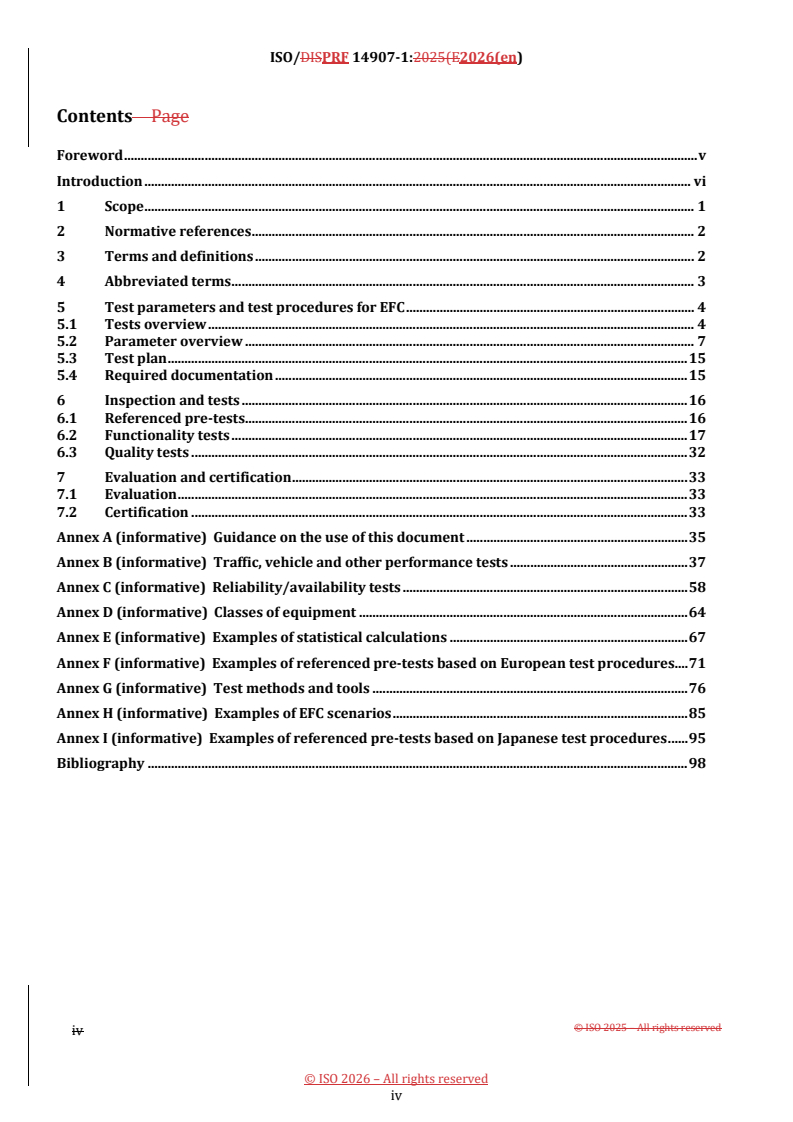
Contents Page
Foreword . v
Introduction . vi
1 Scope . 1
2 Normative references . 2
3 Terms and definitions . 2
4 Abbreviated terms . 3
5 Test parameters and test procedures for EFC . 4
5.1 Tests overview . 4
5.2 Parameter overview . 7
5.3 Test plan . 15
5.4 Required documentation . 15
6 Inspection and tests . 16
6.1 Referenced pre-tests . 16
6.2 Functionality tests . 17
6.3 Quality tests . 32
7 Evaluation and certification . 33
7.1 Evaluation . 33
7.2 Certification . 33
Annex A (informative) Guidance on the use of this document . 35
Annex B (informative) Traffic, vehicle and other performance tests . 37
Annex C (informative) Reliability/availability tests . 58
Annex D (informative) Classes of equipment . 64
Annex E (informative) Examples of statistical calculations . 67
Annex F (informative) Examples of referenced pre-tests based on European test procedures. 71
Annex G (informative) Test methods and tools . 76
Annex H (informative) Examples of EFC scenarios . 85
Annex I (informative) Examples of referenced pre-tests based on Japanese test procedures . 95
Bibliography . 98
iv
iv
ISO/PRF 14907-1:2026(en)
Foreword
ISO (the International Organization for Standardization) is a worldwide federation of national standards
bodies (ISO member bodies). The work of preparing International Standards is normally carried out through
ISO technical committees. Each member body interested in a subject for which a technical committee has been
established has the right to be represented on that committee. International organizations, governmental and
non-governmental, in liaison with ISO, also take part in the work. ISO collaborates closely with the
International Electrotechnical Commission (IEC) on all matters of electrotechnical standardization.
The procedures used to develop this document and those intended for its further maintenance are described
in the ISO/IEC Directives, Part 1. In particular, the different approval criteria needed for the different types of
ISO documentsdocument should be noted. This document was drafted in accordance with the editorial rules
of the ISO/IEC Directives, Part 2 (see www.iso.org/directives).
Attention is drawnISO draws attention to the possibility that some of the elementsimplementation of this
document may beinvolve the subjectuse of (a) patent(s). ISO takes no position concerning the evidence,
validity or applicability of any claimed patent rights in respect thereof. As of the date of publication of this
document, ISO had not received notice of (a) patent(s) which may be required to implement this document.
However, implementers are cautioned that this may not represent the latest information, which may be
obtained from the patent database available at www.iso.org/patents. ISO shall not be held responsible for
identifying any or all such patent rights. Details of any patent rights identified during the development of the
document will be in the Introduction and/or on the ISO list of patent declarations received (see ).
Any trade name used in this document is information given for the convenience of users and does not
constitute an endorsement.
For an explanation of the voluntary nature of standards, the meaning of ISO specific terms and expressions
related to conformity assessment, as well as information about ISO's adherence to the World Trade
Organization (WTO) principles in the Technical Barriers to Trade (TBT)), see
www.iso.org/iso/foreword.html.
The committee responsible for this This document iswas prepared by Technical Committee ISO/TC 204,
Intelligent transport systems., in collaboration with the European Committee for Standardization (CEN)
Technical Committee CEN/TC 278, Intelligent Transport Systems, in accordance with the Agreement on
technical cooperation between ISO and CEN (Vienna Agreement).
This second edition cancels and replaces the first edition of ISO 14907--1:2020, which has been technically
revised.
The main changes are as follows:
— — the presentation of the different test groups has been modified to consistently reflect their typical
sequence (i.e. pre-, functionality- and quality-related tests);
— — terms and definitions have been updated and ISO 17573-2 has been included as the primary source
for harmonized terminology across electronic fee collection (EFC) standards;
— — the references have been revised.
A list of all parts in the ISO 14907 series can be found on the ISO website.
Any feedback or questions on this document should be directed to the user’s national standards body. A
complete listing of these bodies can be found at www.iso.org/members.html.
v
ISO/DISPRF 14907-1:2025(E2026(en)
Introduction
For an electronic fee collection (EFC) system, approvals and tests are required to determine whether the
system (or individual components of the system) conforms to standards and application requirements and to
enable parameters such as quality, availability, and maintainability to be measured.
This document provides a toolbox of tests and procedures for the assessment and proof of EFC systems that
they are suitable for specified EFC applications under specific operational conditions. Depending on the
system to be tested and based on available documentation and the status of previous approvals, this document
helps interested parties, such as system suppliers, operators and testing institutes, make use of already proven
references and identify parameters that still need to be tested according to the specified intended use.
At the time of publication of this document, the determination of common system requirements for Europe
(or any other region) has not been agreed. For this reason, no specific performance requirements are set out
in this document, unless these are already determined elsewhere (such as safety or radio regulations), but
instead the most important parameters that should be included in such requirements specifications are stated.
Where reference to an existing test is available, this document provides that reference. This document defines
only the test and test procedures, not the benchmark figures that these areintend to be measured against.
Benchmark figures which the systems or components under test can be compared with and validated against
will potentially form the subject of a future part of the ISO 14907 series. Within the framework of the European
Electronic Toll Service (EETS), this document maycan provide a basis for the certification of the various
systems' part of the EETS, in particular for assessing their suitability for use.
This document is furthermore limited to automated (electronic) payment using a standardized dedicated
short-range communication (DSRC). The scope of this document does not include manual payment,
conventional money transaction, nor payment by means of sticker, vignettes, tickets, or magnetic-stripe cards,
etc. The applications to which EFC is related are toll collection, road pricing, parking, and individual traffic
information.
This document supports groups of operators to determine common specific performance levels and operating
conditions, whilstwhile allowing for regional variation where needed. It provides operating and
environmental parameters (or classes of operating and environmental parameters) within which such
systems operate without impairing interoperability.
The following guidelines have been followed when selecting the test procedures for test parameters:
— — as far as possible, reference is made to existing standardized test procedures;
— — the focus is placed on those tests that are essential to ensuring that EFC equipment can exchange
information and mutually use the exchanged information.
An overview of the tests and parameters provided by this document is given in 5.15.1 and 5.25.2.
A brief guide describing how to use this document is provided by Annex AAnnex A.
WhilstWhile this document relates to general test procedures, some provisions relate specifically to test
procedures for certification purposes. Many parts of this document are relevant internationally, but
adaptations can be necessary to meet regulations outside Europe Economic Area (EEA).
ISO/TS 37444 provides an examination framework for EFC charging performance.
vi
vi
ISO/PRF 14907-1:2026(en)
This document relates only to the equipment of the user and the service provider as illustrated in
Figure 1Figure 1.
Figure 1— — Conceptual model of EFC
The scope of this document relates solely to on-board equipment (OBE) and roadside equipment (RSE)), and
the DSRC interface between OBE and RSE including its functions to perform the fee collection as illustrated by
Figure 2Figure 2.
vii
ISO/DISPRF 14907-1:2025(E2026(en)
Figure 2 — OBE/RSE interface and associated environments
viii
viii
International Standard ISO 14907-1:2026(en)
Electronic fee collection — Test procedures for user and fixed
equipment —Part 1: —
Part 1:
Description of test procedures
1 Scope
This document specifies the test procedures for roadside equipment (RSE and on-board equipment (OBE for
electronic fee collection (EFC) with regard to conformance to standards and requirements for type approval
and acceptance testing.
The scope of this document is restricted to systems operating within the radio emission, electromagnetic
compatibility (EMC) regulations, traffic, and other regulations of the regions in which they are operated.
This document identifies a set of suitable parameters and provides test procedures to enable the proof of a
complete EFC system, as well as components of an EFC system, e.g. OBE, related to the defined requirements
of an application. The defined parameter and tests are assigned to the following groups of parameters:
— — functionality;
— — quality;
— — referenced pre-tests.
This document describes procedures, methods and tools, and a test plan which shows the relation between all
tests and the sequence of these tests. It lists all tests that are required to measure the performance of EFC
equipment. It describes which EFC equipment is covered by the test procedures; the values of the parameters
to be tested are not included. It also describes how the tests are intended to be performed, and which tools
and prerequisites are necessary before this series of tests can be undertaken. It is assumed that the security
of the system is inherent in the communications and EFC functionality tests, therefore they are not addressed
in this document. All tests in this document provide instructions on how to evaluate the test results.
This document defines only the tests and test procedures, not the benchmark figures that thesevalues against
which they are intended to be measured against. The test procedures defined in this document can be used as
input, e.g. by scheme owners, for prototype testing, type approvals, tests of installations and periodic
inspections.
Related to a conceptual model of an EFC system, this document relates only to the equipment of the user and
the service provider.
EFC systems for DSRC consist, in principle, of a group of technical components, which in combination fulfil the
functions required for the collection of fees by electronic automatic means. These components comprise all,
or most, of the following:
— — OBE within a vehicle;
— — OBE containing the communications and computing sub-functions;
ISO/DISPRF 14907-1:2025(E2026(en)
— — optional integrated circuit card which maycan carry electronic money, service rights, and other
secured information;
— — communication between OBE and RSE based on DSRC;
— — equipment for the fee collection at the RSE containing the communications and computing sub-
functions;
— — equipment for the enforcement at the roadside;
— — central equipment for the administration and operation of the system.
The scope of this document relates solely to OBE and RSE and the DSRC interface between OBE and RSE
including its functions to perform the fee collection. All the equipment used for enforcement (e.g. detection,
classification, localization, and registration) and central equipment are outside the scope of this document.
A brief guide describing how to use this document is provided by Annex A.
2 Normative references
The following documents are referred to in the text in such a way that some or all of their content constitutes
requirements of this document. For dated references, only the edition cited applies. For undated references,
the latest edition of the referenced document (including any amendments) applies.
ISO/IEC 17025:2017, General requirements for the competence of testing and calibration laboratories
ISO/IEC 17065:2012, Conformity assessment — Requirements for bodies certifying products, processes and
services
ISO 17573--2, Electronic fee collection — System architecture for vehicle related tolling — Part 2: Vocabulary
3 Terms and definitions
For the purposes of this document, the terms and definitions given in ISO 17573-2 and the following apply.
ISO and IEC maintain terminologicalterminology databases for use in standardization at the following
addresses:
— — ISO Online browsing platform: available at https://www.iso.org/obp
— — IEC Electropedia: available at https://www.electropedia.org/
3.1 3.1
decision
conclusion based on the results of review, that fulfilment of specified requirements has or has not been
demonstrated
[SOURCE: ISO/IEC 17000:2020, 7.2]
ISO/PRF 14907-1:2026(en)
3.2 3.2
electronic fee collection equipment
EFC equipment
equipment comprising roadside equipment (RSE) and on-board equipment (OBE)
3.3 3.3
review
consideration of the suitability, adequacy and effectiveness of selection and determination activities, and the
results of these activities, with regard to fulfilment of specified requirements by an object of conformity
assessment
[SOURCE: ISO/IEC 17000:2020, 2.47.1]
3.4 3.4
test status
nature of a test, either basic or conditional
Note 1 to entry: A test labelled “conditional” is performed if, and only if, it is applicable to a feature identified in the
specification of the system or component, whereas a test labelled “basic” indicates a highly recommended test as part of
a foundation for meaningful evaluation. See 5.25.2.
4 Abbreviated terms
ARIB Association of Radio Industries and Businesses
NOTE A Japanese standards development organisationorganization.
DSRC dedicated short-range communication
EAL evaluation assurance level
EEA European Economic Area
EFC electronic fee collection
EIRP effective isotropic radiated power
EMC electromagnetic compatibility
ETSI European Telecommunications Standards Institute
ICC integrated circuit(s) card
IEC International Electrotechnical Commission
MMI man-machine interface
MTBF mean time between failure
MTTF mean time to failure
MTTR mean time to repair
OBE on-board equipment
OBU on-board unit
QPSK quadrature phase shift keying
RSE roadside equipment
SUT system under test
tbd to be determined
TOE target of evaluation
ISO/DISPRF 14907-1:2025(E2026(en)
5 Test parameters and test procedures for EFC
5.1 Tests overview
5.1.1 General
The test parameters for EFC systems or components are categorized ininto three groups as follows:
a) a) referenced pre-tests;
b) b) functionality tests;
c) c) quality tests.
Figure 3Figure 3 shows the general structure of all test parameter groups relevant for EFC systems and those
which are relevant to this document. The specific test parameters that are ultimately deemed relevant for a
specific EFC system shall be identified and listed in the test plan according to 5.35.3. The individual test plan
for type approval or acceptance testing shall consider those pre-tests that have already been passed, i.e. for
EMC, DSRC, and environment.
ISO/PRF 14907-1:2026(en)
ISO/DISPRF 14907-1:2025(E2026(en)
Figure 3 — Test plan — Interdependencies
Annex A provides a brief guide on how to use this document.
5.1.2 Referenced pre-tests
The third category of tests is related to test parameters which are fundamental for the performance of EFC
equipment. The specific parameters and requirements are not within the scope of this document. The
parameters that are relevant can be assigned to the following groups:
— — DSRC;
— — EMC;
— — environment.
5.1.3 Functionality tests
The first category of tests is related to test procedures which aim to verify the functionality of the EFC
equipment.
ISO/PRF 14907-1:2026(en)
The functionality tests are related to the essential test parameters that need toshall be applied to verify the
performance and capability of EFC equipment of different vendors and system operators.
The following parameters shall be tested:
— — communication;
— — EFC application;
— — influence of vehicle characteristics;
— — influence of traffic characteristics;
— — environmental influences.
Communication and EFC application tests are described in 6.16.1. Tests related to vehicle and traffic
characteristics and environmental influences are listed in Annex BAnnex B.
5.1.4 Quality tests
The second category of tests is related to procedures that aim to determine the quality of the EFC equipment.
These are relevant for both operators and users.
The following test parameters shall be tested:
— — quality management;
— — reliability;
— — availability.
Test procedures are already available for some of these test parameters (see 6.26.2 and Annex CAnnex C).).
These tests are described in 6.26.2 and Annex CAnnex C.
5.2 Parameter overview
Tables 1Tables 1 to 33 provide a comprehensive list of the parameters that are relevant for type approval or
acceptance testing of a complete EFC system, as well as components of an EFC system. The tables are divided
according to the subjects of 5.1.2, 5.1.35.1.2, 5.1.3,, and 5.1.45.1.4:: pre-tests, functionality and quality. The
subclause in which the tests are described or referenced is shown. An indication as to the nature of these tests
(basic or conditional) is provided as not all tests are relevant to all operators and their specific operating
situations and environment.
As used in Tables 1Tables 1 to 33,,
— — “basic” means that the identified tests are highly recommended as part of a foundation for meaningful
evaluation, and
— — “conditional” means that the test shall be performed if, and only if, it is applicable to a feature identified
in the specification of the system or component under evaluation, for example, performing the lane
changing test (T6) if the RSE is characterized as multilane.
Table 1Table 1 provides a list of parameters that are necessary for pre-tests and whose performance and
conformance are tested by reference to existing standards or Technical Specifications.
ISO/DISPRF 14907-1:2025(E2026(en)
Table 2Table 2 provides an overview of the parameters for which tests are defined in this document to
measure the performance and assess the level of conformance of an EFC system or components under test.
Table 3Table 3 provides a list of the quality tests.
NOTE The tests have been categorized into inspection tests, laboratory tests, simulation tests, and field tests. The
appropriate test or types of tests are indicated, in the following tables, for each parameter. It is not expected that all the
named types of tests for a parameter will be performed on that parameter. Where a set of appropriate tools is available
to a test house, it is up to the test house to decide which type of test is most appropriate to meet its specific remit.
Where a particular category of test shall be performed to conform to this document, the test is indicated in the
following tables with a “p”. Where a particular category of test is optional, this is indicated with an “o”.
ISO/PRF 14907-1:2026(en)
Table 1 — Referenced pre-tests
Tests Location Test status Test type
(R = refer to standards/regulations
Reference to subclause Basic/
Parameter Item Name
a
conditional which specify these pre-tests)
D1 Layer 1 6.1.26.1.1, F.1, F.1 B R
DSRC D2 Layer 2 6.1.26.1.1, F.1, F.1 B R
D3 Layer 7 6.1.26.1.1, F.1, F.1 B R
ET1 Basic parameter 6.1.36.1.2, F.2, F.2 B R
ET2 Mechanical 6.1.36.1.2, F.2, F.2 B R
Environment ET3 Electrical 6.1.36.1.2, F.2, F.2 B R
ET4 Chemical/biological 6.1.36.1.2, F.2, F.2 B R
ET5 Safety 6.1.36.1.2, F.2, F.2 B R
E1.1 Emission 6.1.46.1.3, F.3, F.3 B R
EMC
E1.2 Immunity 6.1.46.1.3, F.3, F.3 B R
a
Test shall only be applied if function or item is specified.
International Standard ISO 14907-1:2026(en)
Table 2 — Functionality
Applicable test type
Tests Location Test status
(p = shall be performed, o = optional)
Reference Basic/
Parameter Item Name Inspection Laboratory Simulation Field test
a
to subclause conditional
Category 1
Communication C1 Conformance assessment 6.2.16.2.1 B — p o o
F1 Validation of the specification 6.2.26.2.2 B p — — —
EFC
application F2 Implementation test 6.2.26.2.2 B p o o o
tests
F3 Functionality tests 6.2.26.2.2 B p o o p
6.2.36.2.3, B.2,
T1 Longitudinal distance between vehicles B — — o p
B.2
6.2.36.2.3, B.2,
T2 Lateral distance between vehicles C — — o o
B.2
6.2.36.2.3, B.2,
T3 Lateral distance between OBE C — — o o
B.2
6.2.36.2.3, B.2,
T4 Speed of vehicles C — — o o
B.2
6.2.36.2.3, B.2,
T5 Driving angle C — — o o
B.2
Traffic
conditions
6.2.36.2.3, B.2,
T6 Lane changing C — — o o
B.2
6.2.36.2.3, B.2,
T7 Shadowing B — — o p
B.2
ISO/PRF 14907-1:2026(en)
Applicable test type
Tests Location Test status
(p = shall be performed, o = optional)
Reference Basic/
Parameter Item Name Inspection Laboratory Simulation Field test
a
to subclause conditional
6.2.36.2.3, B.2,
T8 Traffic scenarios — free flow C — — o o
B.2
6.2.36.2.3, B.2,
T9 Traffic scenarios — restricted flow C — — o o
B.2
6.2.36.2.3, B.2,
T10 Traffic volume C — — o o
B.2
Category 2
V1 6.2.46.2.4, B.3, C — — o o
Length of vehicle
B.3
6.2.46.2.4, B.3,
V2 C — — o o
Height of vehicle
B.3
V3 6.2.46.2.4, B.3, C — — o o
Width of vehicle
B.3
Vehicle
characteristics
V4 6.2.46.2.4, B.3, C — — o o
Length of bonnet
B.3
V5 Other vehicle features, weight, number of 6.2.46.2.4, B.2, C — — o o
axles, volume, shape, paintwork, colour, air B.2
conditioner, mobile communication
equipment
V6 Constructive elements, superstructures in 6.2.46.2.4, B.3, C — — o o
the windscreen area, lorries with external B.3
sun visors, car transporters with projecting
loading surface sunroof
(open/closed)/roof mountings
V7 Attenuation of windscreen, caused by e.g. 6.2.46.2.4, B.3, C — o o o
metallized or dirty windscreen B.3
ISO/DISPRF 14907-1:2025(E2026(en)
Applicable test type
Tests Location Test status
(p = shall be performed, o = optional)
Reference Basic/
Parameter Item Name Inspection Laboratory Simulation Field test
a
to subclause conditional
V8 Angle of windscreens, horizontal plane 6.2.46.2.4, B.3, C — o o o
cars, small trucks and vans, trucks, buses, B.3
and coaches
V9 Angle of windscreens, vertical plane 6.2.46.2.4, B.3, C — o o o
location in the outer curve area B.3
V10 6.2.46.2.4, B.3, C — o o o
Mounting height of OBE antenna
B.3
V11 Lateral mounting of OBE antenna from 6.2.46.2.4, B.3, C — o o o
middle of windscreen B.3
V12 OBE behaviour, variation of supply voltage, 6.2.46.2.4, B.3, C — o o o
operational state of OBE, fixing of OBE, B.3
integrated circuit card (ICC) behaviour
Category 3
I1 Width of pavement 6.2.56.2.5, B.4, C o — o o
B.4
I2 Number of lanes 6.2.56.2.5, B.4, C o — o o
B.4
Environmental I3 Other topographical influences 6.2.56.2.5, B.4, C o o o o
influences B.4
I4 Water and dust 6.2.56.2.5, B.4, C — o o o
B.4
I5 Temperature, humidity, and daylight 6.2.56.2.5, B.4, C — o o o
B.4
ISO/PRF 14907-1:2026(en)
Applicable test type
Tests Location Test status
(p = shall be performed, o = optional)
Reference Basic/
Parameter Item Name Inspection Laboratory Simulation Field test
a
to subclause conditional
I6 Other weather conditions 6.2.56.2.5, B.4, C — o o o
B.4
a Test shall only be applied if function or item is specified.
ISO/DISPRF 14907-1:2025(E2026(en)
Table 3 — Quality
Applicable test type
Tests Location Test status
(p = shall be performed, o = optional)
Reference Basic/
Parameter Item Name Inspection Laboratory Simulation Field test
a
to subclause conditional
Quality Q1 Design, development, production, 6.3.16.3.1 B p — — —
management installation, and servicing
R1 Components, equipment, system 6.3.26.3.2, C.1, B p o o o
C.1
R2 Transaction-level reliability 6.3.26.3.2, C.2, B p o o o
C.2
Reliability/ R3 OBE life duration 6.3.26.3.2, C.2, B p o o o
availability C.2
R4 OBE battery duration 6.3.26.3.2, C.2, B p o o o
C.2
R5 OBE smart card life duration 6.3.26.3.2, C.2, B p o o o
C.2
a Test shall only be applied if function or item is specified.
ISO/PRF 14907-1:2026(en)
5.3 Test plan
The manufacturer, the operator or the test house, or a combination of these, carrying out the type of approval
or acceptance testing shallare expected to devise an individual test plan for each tested EFC system or EFC
component, according to Figure 3in accordance with Figure 3,, considering the system-specific characteristics
of the EFC application. With respect to type approval, the requirements of applicable standards or other
normative and referenced documents shallapply and are expected to be tested by the manufacturer or the
operator or by a test house.
With respect to acceptance tests, only the features that are specified or implicit in the system specification
shallare expected to be tested. Where additional features are provided for contingent use at a future date,
these shallare expected to be tested only if such contingency is included in the system specification. Where
additional features are present in products supplied but are neither used nor included in the system
specification or implementation, these shallare expected only to be tested if they affect the operation of the
system.
Results of pre-tests that have already been passed shall be compared with the application-specific
requirements. If deviations are detected, additional tests will needare expected to be carried out. The test plan
shall make references to each listed test parameter with respect to the following details:
— — identification of test parameter and item;
— — reference of the related requirements/severity of the test;
— — required equipment and documentation;
— — selected test type;
— — required test equipment, measurement equipment, interfaces, and tools;
— — required test environment;
— — department carrying out the test;
— — required documentation of the tests and the results (see G.5G.5).).
Interdependencies between the results of the different tests are anticipated and shallshould be considered by
the manufacturer or the test house. An example test protocol form is given in Clause G.5Clause G.5.
5.4 Required documentation
The following listed documentation shall be supplied by the manufacturer to conduct the tests defined by a
test plan:
— — system description (overview, block diagrams);
— — system specification including functions, timing, operational data on a detailed level;
— — safety and security concept (threat analysis, implemented measures to detect and control failures,
threats, and manipulations);
— — user documentation (service provider and user);
— — specification of ambient conditions;
— — operational directives;
ISO/DISPRF 14907-1:2025(E2026(en)
— — quality assurance directives, development rules;
— — maintenance and installation directives;
— — list of all available documents from the manufacturer relating to the EFC system under test created
during the design and manufacture of the equipment.
6 Inspection and tests
6.1 Referenced pre-tests
6.1.1 General
It shall be ensured that the EFC roadside and on-board equipment comply with the radio equipment
regulations and standards applicable in the countries and regions in which it will be operated.
EXAMPLE 1 Annex F 1 provides examples of referenced pre-tests based on European test procedures, which are
relevant to consider in the European Economic Area (EEA).
[61][60]
EXAMPLE 2 Directive 2014/53/EU is applicable for the provision of radio equipment on the European
Economic Area (EEA)EEA market.
EXAMPLE 2 Annex I 3 Annex I provides examples of referenced pre-tests based on Japanese test procedures.
The relevant parameters shall be considered during the specification of a test plan. Results of previously
performed tests and approvals shall be taken into account and shall be compared with the requirements of
the specific EFC application.
6.1.16.1.2 DSRC
The range of the DSRC tests shall cover the following areas:
— — physical layer at 5,8 GHz;
— — data link layer;
— — application link layer.
Examples of referenced DSRC tests are listed in Clause F.1Clause F.1.
6.1.26.1.3 Environment
The range of the environment tests shall cover the following areas:
— — climate;
— — mechanical;
— — electrical;
— — chemical/biological;
— — safety.
ISO/PRF 14907-1:2026(en)
Examples of referenced environment tests are listed in Clause F.2Clause F.2.
6.1.36.1.4 EMC
The range of the EMC tests shall cover the areas:
— — emission;
— — immunity.
Examples of referenced environment tests are listed in Clause F.3Clause F.3.
6.2 Functionality tests
6.2.1 Communication
The test specifications regarding communication are defined in ISO 14907-2. It specifies the tests that verify
on-board unit (OBU) conformance of implemented communication (transaction) protocols to conform with
the specifications given in ISO 14906 to be used for EFC applications.
NOTE ISO 14907--2 can also be used as a source of inspiration for roadside equipment testing in accordance with
ISO 14906.
ISO 14907--2 describes general requirements for conformance testing and specific test procedures for the
following:
— — basic DSRC L7 functionality;
— — EFC application functions;
— — EFC attributes;
— — addressing procedures of EFC attributes and (hardware) components, e.g. ICC and man-machine
interface (MMI);
— — EFC transaction model;
— — behaviour of the interface.
6.2.2 EFC application
6.2.2.1 General
The tests are related to components or to a complete EFC system consisting of an OBE, RSE, or both and
RSE/OBE in combination. The objective of the tests is to validate that the equipment to be tested fulfils the
functional and technical requirements of the specification. The proof consists of inspections, simulations, and
tests which are intended to ensure that the system specifications and the equipment of EFC are in conformance
with the EFC requirements based on standards and regulations, national requirements, and other
requirements.
6.2.2.2 and 6.2.2.3 describe a set of tests (see also Annex BAnnex B);); which of those tests are relevant and
sufficient to prove the performance of an EFC system or its components shall be defined by a test plan (see
5.35.3).).
The EFC application test is divided into two sections:
ISO/DISPRF 14907-1:2025(E2026(en)
a) a) validation of the EFC specification;
b) b) inspection and test of the EFC system under test (SUT) or component under test.
The relationship between the test sections is shown in Figure 4Figure 4.
ISO/PRF 14907-1:2026(en)
ISO/DISPRF 14907-1:2025(E2026(en)
Figure 4— — Structure of application tests
6.2.2.26.2.2.2 addresses the validation of the EFC system specification with respect to the design specification.
The objective is a validation of the system specification to verify that it is in conformance with the EFC
requirements based on standards and regulations, national requirements, and other requirements. The
activity consists of inspection and analysis of the referenced documentation. The output of this phase is an
authorized and valid system specification of the SUT which meets the requirements of the selected standards
and regulations. Additionally, a test plan will beis specified which identifies the required test steps to prove
the performance of the SUT.
6.2.2.36.2.2.3 addresses EFC equipment that is designed according to a validated system specification. The
activities of this section are inspections, simulations, and tests. Before the functionality test can start, an
implementation test (pre-test after installation) is carried out to ensure the principal performance of the
system. The implementation includes the activities of installation and commissioning. The objective of the
tests is to validate the conformity of the equipment with the specification and compliance with the EFC
requirements of standards and regulations, national requirements, and other requirements.
The inspection and test shall take into consideration results of tests that have been previously performed, e.g.
quality tests and reference tests, and shall be detailed by a test plan (see 5.35.3). Annex B). Annex B contains
a list of tests that are related to traffic conditions, vehicle characteristics, and other environment influences.
Annex HAnnex H provides examples of EFC scenarios as part of a functionality test.
ISO/PRF 14907-1:2026(en)
6.2.2.2 Validation of the SUT specification
— Table 4Table 4 shows the form for the validation of the specification for the system under test.
Table 4 — Validation of the specification
EFC application test
Name: Validation of the specification (F1)
Group: EFC application
Purpose: To ensure that the specification of the SUT or component is in conformance with the EFC
requirements of standards and regulations, national requirements, and user requirements.
— — National requirements for EFC.
Requirement
reference:
— — EFC requirements for a DSRC communication.
— — User requirements of the specified EFC application.
Default: All specifications to be inspected shallare expected to be in conformance regardingwith the
DSRC regulations and DSRC standards applicable in the countries and regions in which the
system or component will be operated.
Test A set of documentation as listed in 5.45.4 is required.
configuration:
Behaviour The task consists of inspection and analysis (Annex G(Annex G)) of the provided
description: documentation. The details of the system specification of the SUT are compared with the
requirements of the EFC standards and regulations, national requirements, and user
requirements.
The documentation is inspected concerning completeness, validity, unambiguity,
consistency, and understandability.
The analysis is carried out to evaluate the system structure, reliability figures, measures to
detect and control failures, timing behaviour, security and safety, maintenance, and other
technical and non-technical measures concerning system performance.
Constraints None
reference:
Verdict: Test result Verdict
Authorized and valid system specification of Pass
the SUT. Test plan for the performance proof.
The system specification does not conform to Fail
the requirements. List of discovered
deviations.
Comments:
6.2.2.3 Inspection and test of SUT
Table 5Table 5 shows the form for the implementation of test.
Table 5 — Implementation of test
EFC application test
Name: Implementation test (F2)
Group: EFC application
ISO/DISPRF 14907-1:2025(E2026(en)
EFC application test
Purpose: The objective of this test is to verify that the specified EFC system (SUT) or component is in
conformance with the fundamental requirements of the EFC application.
Requirement Validated system specification of the SUT.
reference:
Default: Certified DSRC equipment according to the requirements of DSRC regulations and
standards applicable in the countries and regions in which the system or component
will be operated.
— — Documentation and equipment according to test plan (see 5.3).
Test
configuration:
— — Test facilities according to test plan.
Behaviour The SUT or component shall be tested according to the specified requirements.
description: Prerequisite for the inspection and test is a validation of the system specification, certified
DSRC equipment according to the DSRC standards and a qualification of the SUT in
accordance with other fundamental requirements.
The qualification of this phase consists of inspection, test, and simulation. The work is
separated into the following steps:
1) 1. Verification of the qual
...